Page is loading ...

For more product details, please visit GIGABYTE's website.
To reduce the impacts on global warming, the packaging materials of this product are
recyclable and reusable. GIGABYTE works with you to protect the environment.
GA-Z170-HD3 GA-Z170-HD3 DDR3
GA-Z170-HD3
GA-Z170-HD3 DDR3
User's Manual
Rev. 1003
12ME-Z170HD3-1003R

Copyright
© 2016 GIGA-BYTE TECHNOLOGY CO., LTD. All rights reserved.
The trademarks mentioned in this manual are legally registered to their respective owners.
Disclaimer
Information in this manual is protected by copyright laws and is the property of GIGABYTE.
Changes to the specications and features in this manual may be made by GIGABYTE without prior notice.
No part of this manual may be reproduced, copied, translated, transmitted, or published in any form or
by any means without GIGABYTE's prior written permission.
In order to assist in the use of this product, carefully read the User's Manual.
For product-related information, check on our website at: http://www.gigabyte.com
Identifying Your Motherboard Revision
The revision number on your motherboard looks like this: "REV: X.X." For example, "REV: 1.0" means
the revision of the motherboard is 1.0. Check your motherboard revision before updating motherboard
BIOS, drivers, or when looking for technical information.
Example:
Motherboard
GA-Z170-HD3
GA-Z170-HD3 DDR3
Jul. 17, 2015
Jul. 17, 2015
Motherboard
GA-Z170-HD3
GA-Z170-HD3 DDR3

- 3 -
Table of Contents
GA-Z170-HD3 Motherboard Layout ................................................................................4
GA-Z170-HD3 DDR3 Motherboard Layout ......................................................................5
Chapter 1 Hardware Installation .....................................................................................6
1-1 Installation Precautions .................................................................................... 6
1-2 ProductSpecications ...................................................................................... 7
1-3 Installing the CPU and CPU Cooler ............................................................... 10
1-4 Installing the Memory ..................................................................................... 10
1-5 Installing an Expansion Card ......................................................................... 11
1-6 Back Panel Connectors .................................................................................. 11
1-7 Internal Connectors ........................................................................................ 13
Chapter 2 BIOS Setup ..................................................................................................21
2-1 Startup Screen ............................................................................................... 21
2-2 M.I.T. .............................................................................................................. 22
2-3 System Information ........................................................................................ 27
2-4 BIOS Features ............................................................................................... 28
2-5 Peripherals ..................................................................................................... 31
2-6 Chipset ........................................................................................................... 33
2-7 Power Management ....................................................................................... 34
2-8 Save & Exit ..................................................................................................... 36
Chapter 3 Appendix ......................................................................................................37
3-1 ConguringaRAIDSet .................................................................................. 37
3-2 Drivers Installation .......................................................................................... 39
Regulatory Statements .............................................................................................. 40
Contact Us ................................................................................................................ 44

- 4 -
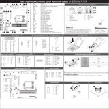
GA-Z170-HD3 Motherboard Layout
The box contents above are for reference only and the actual items shall depend on the product package you obtain.
The box contents are subject to change without notice.
Box Contents
5GA-Z170-HD3 motherboard 5Two SATA cables
5Motherboard driver disk 5I/O Shield
5User's Manual 5One G Connector
KB_MS_USB
CPU_FAN
ATX_12V_2X4
ATX
F_AUDIO
AUDIO
B_BIOS
PCIEX4
DDR4_2
DDR4_1
DDR4_4
DDR4_3
BAT
F_PANEL
COMA
Intel® Z170
PCI2 CLR_CMOS
CODEC
M_BIOS
PCIEX1_1
PCIEX16
SPDIF_O F_USB1
LGA1151
GA-Z170-HD3
VGA
DVI
HDMI
R_USB30
USB30_LAN
SATA EXPRESS
F_USB30_2
PCIEX1_2
SATA3
iTE®
Super I/O
SYS_FAN2
F_USB2LPT
SYS_FAN1
TPM
M2A_32G
Realtek®
GbE LAN
SATA3 3 2
5 4
1 0
SATA EXPRESS
F_USB30_1
THB_C
80A 60A 42A
PCI1
SYS_FAN3
PCIe to
PCI Bridge

- 5 -
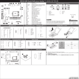
GA-Z170-HD3 DDR3 Motherboard Layout
The box contents above are for reference only and the actual items shall depend on the product package you obtain.
The box contents are subject to change without notice.
Box Contents
5GA-Z170-HD3 DDR3 motherboard 5Two SATA cables
5Motherboard driver disk 5I/O Shield
5User's Manual 5One G Connector
KB_MS_USB
CPU_FAN
ATX_12V_2X4
ATX
F_AUDIO
AUDIO
B_BIOS
PCIEX4
DDR3_2
DDR3_1
DDR3_4
DDR3_3
BAT
F_PANEL
COMA
Intel® Z170
PCI2 CLR_CMOS
CODEC
M_BIOS
PCIEX1_1
PCIEX16
SPDIF_O F_USB1
LGA1151
GA-Z170-HD3 DDR3
VGA
DVI
HDMI
R_USB30
USB30_LAN
SATA EXPRESS
F_USB30_2
PCIEX1_2
SATA3
iTE®
Super I/O
SYS_FAN2
F_USB2LPT
SYS_FAN1
TPM
M2A_32G
Realtek®
GbE LAN
SATA3 3 2
5 4
1 0
SATA EXPRESS
F_USB30_1
THB_C
80A 60A 42A
PCI1
SYS_FAN3
PCIe to
PCI Bridge

Chapter 1 Hardware Installation
1-1 Installation Precautions
The motherboard contains numerous delicate electronic circuits and components which can become
damaged as a result of electrostatic discharge (ESD). Prior to installation, carefully read the user's
manual and follow these procedures:
•Prior to installation, make sure the chassis is suitable for the motherboard.
•Prior to installation, do not remove or break motherboard S/N (Serial Number) sticker or
warranty sticker provided by your dealer. These stickers are required for warranty validation.
•Always remove the AC power by unplugging the power cord from the power outlet before
installing or removing the motherboard or other hardware components.
•When connecting hardware components to the internal connectors on the motherboard, make
sure they are connected tightly and securely.
•When handling the motherboard, avoid touching any metal leads or connectors.
•It is best to wear an electrostatic discharge (ESD) wrist strap when handling electronic
components such as a motherboard, CPU or memory. If you do not have an ESD wrist strap,
keepyourhandsdryandrsttouchametalobjecttoeliminatestaticelectricity.
•Prior to installing the motherboard, please have it on top of an antistatic pad or within an
electrostatic shielding container.
•Before connecting or unplugging the power supply cable from the motherboard, make sure
the power supply has been turned off.
•Before turning on the power, make sure the power supply voltage has been set according to
the local voltage standard.
•Before using the product, please verify that all cables and power connectors of your hardware
components are connected.
•To prevent damage to the motherboard, do not allow screws to come in contact with the
motherboard circuit or its components.
•Make sure there are no leftover screws or metal components placed on the motherboard or
within the computer casing.
•Do not place the computer system on an uneven surface.
•Do not place the computer system in a high-temperature or wet environment.
•Turning on the computer power during the installation process can lead to damage to system
components as well as physical harm to the user.
•If you are uncertain about any installation steps or have a problem related to the use of the
product,pleaseconsultacertiedcomputertechnician.
•If you use an adapter, extension power cable, or power strip, ensure to consult with its installation
and/or grounding instructions.
- 6 -

1-2 ProductSpecications
CPU Support for Intel® Core™ i7 processors/Intel® Core™ i5 processors/
Intel® Core™ i3 processors/Intel® Pentium® processors/
Intel® Celeron® processors in the LGA1151 package
(Go to GIGABYTE's website for the latest CPU support list.)
L3 cache varies with CPU
Chipset Intel® Z170 Express Chipset
Memoryj 4 x DDR4 DIMM sockets supporting up to 64 GB of system memory
* Due to a Windows 32-bit operating system limitation, when more than 4 GB of physical
memory is installed, the actual memory size displayed will be less than the size of
the physical memory installed.
Dual channel memory architecture
Support for DDR4 2133 MHz memory modules
Support for ECC UDIMM 1Rx8/2Rx8 memory modules (operate in non-ECC mode)
Support for non-ECC UDIMM 1Rx8/2Rx8/1Rx16 memory modules
SupportforExtremeMemoryProle(XMP)memorymodules
(Go to GIGABYTE's website for the latest supported memory speeds and memory
modules.)
Memoryk 4 x DDR3 DIMM sockets supporting up to 32 GB of system memory
* Due to a Windows 32-bit operating system limitation, when more than 4 GB of physical
memory is installed, the actual memory size displayed will be less than the size of
the physical memory installed.
Dual channel memory architecture
Support for DDR3 1600/1333 MHz memory modules
Support for ECC UDIMM 1Rx8/2Rx8 memory modules (operate in non-ECC mode)
Support for non-ECC UDIMM 1Rx8/2Rx8 memory modules
SupportforExtremeMemoryProle(XMP)memorymodules
(Go to GIGABYTE's website for the latest supported memory speeds and
memory modules.)
Onboard
Graphics
Integrated Graphics Processor- Intel® HD Graphics support:
- 1 x D-Sub port, supporting a maximum resolution of 1920x1200@60 Hz
- 1 x DVI-D port, supporting a maximum resolution of 1920x1200@60 Hz
* The DVI-D port does not support D-Sub connection by adapter.
-
1 x HDMI port, supporting a maximum resolution of 4096x2160@24 Hz
* Support for HDMI 1.4 version.
Support for up to 3 displays at the same time
Maximum shared memory of 512 MB
Audio Realtek® ALC887 codec
HighDenitionAudio
2/4/5.1/7.1-channel
Support for S/PDIF Out
LAN Realtek® GbE LAN chip (10/100/1000 Mbit)
Expansion Slots 1 x PCI Express x16 slot, running at x16 (PCIEX16)
* For optimum performance, if only one PCI Express graphics card is to be installed,
be sure to install it in the PCIEX16 slot.
- 7 -
j Only for GA-Z170-HD3.
k Only for GA-Z170-HD3 DDR3.

Expansion Slots 1 x PCI Express x16 slot, running at x4 (PCIEX4)
2 x PCI Express x1 slots
(All of the PCI Express slots conform to PCI Express 3.0 standard.)
2 x PCI slots
Multi-Graphics
Technology Support for 2-Way AMD CrossFire™ technology
Storage Interface Chipset:
- 1 x M.2 Socket 3 connector (Socket 3, M key, type 2242/2260/2280 SATA &
PCIe x4/x2/x1 SSD support)
- 3 x SATA Express connectors
- 6 x SATA 6Gb/s connectors
- Support for RAID 0, RAID 1, RAID 5, and RAID 10
* Referto"1-7InternalConnectors,"forthesupportedcongurationswiththeM.2,
SATA Express, and SATA connectors.
USB Chipset:
- 8 x USB 3.0/2.0 ports (4 ports on the back panel, 4 ports available through
the internal USB headers)
- 6 x USB 2.0/1.1 ports (2 ports on the back panel, 4 ports available through
the internal USB headers)
Internal
Connectors
1 x 24-pin ATX main power connector
1 x 8-pin ATX 12V power connector
1 x M.2 Socket 3 connector
3 x SATA Express connectors
6 x SATA 6Gb/s connectors
1 x CPU fan header
3 x system fan headers
1 x front panel header
1 x front panel audio header
1 x S/PDIF Out header
2 x USB 3.0/2.0 headers
2 x USB 2.0/1.1 headers
1 x Trusted Platform Module (TPM) header
1 x Thunderbolt™ add-in card connector
1 x serial port header
1 x parallel port header
1 x Clear CMOS jumper
Back Panel
Connectors
1 x PS/2 keyboard/mouse port
1 x D-Sub port
1 x DVI-D port
1 x HDMI port
4 x USB 3.0/2.0 ports
2 x USB 2.0/1.1 ports
1 x RJ-45 port
6 x audio jacks (Center/Subwoofer Speaker Out, Rear Speaker Out, Side Speaker
Out, Line In, Line Out, Mic In)
I/O Controller iTE® I/O Controller Chip
Hardware
Monitor
System voltage detection
CPU/System temperature detection
CPU/System fan speed detection
CPU/System overheating warning
- 8 -

Hardware
Monitor
CPU/System fan fail warning
CPU/System fan speed control
* Whether the fan speed control function is supported will depend on the cooler you
install.
BIOS 2x64Mbitash
Use of licensed AMI UEFI BIOS
Support for DualBIOS™
PnP 1.0a, DMI 2.7, WfM 2.0, SM BIOS 2.7, ACPI 5.0
Unique Features Support for APP Center
* Available applications in APP Center may vary by motherboard model. Supported
functionsofeachapplicationmayalsovarydependingonmotherboardspecications.
- 3D OSD
- @BIOS
- AutoGreen
- Cloud Station
- EasyTune
- Easy RAID
- Fast Boot
- Smart TimeLock
- Smart Keyboard
- Smart Backup
- System Information Viewer
- USB Blocker
Support for Q-Flash
Support for Smart Switch
Support for Xpress Install
Bundled
Software
Norton® Internet Security (OEM version)
Intel® Smart Response Technology
cFosSpeed
Operating
System Support for Windows 10/8.1/7
Form Factor ATX Form Factor; 30.5cm x 19.9cm
* GIGABYTEreservestherighttomakeanychangestotheproductspecicationsandproduct-relatedinformationwithout
prior notice.
Please visit GIGABYTE's website for support lists of CPU, memory modules,
SSDs, and M.2 devices.
GA-Z170-HD3 GA-Z170-HD3 DDR3
Please visit the Support\Utility page on GIGABYTE's website to download the latest version
of apps.
- 9 -

1-3 Installing the CPU and CPU Cooler
Read the following guidelines before you begin to install the CPU:
•Make sure that the motherboard supports the CPU.
(Go to GIGABYTE's website for the latest CPU support list.)
•Always turn off the computer and unplug the power cord from the power outlet before installing the
CPU to prevent hardware damage.
•Locate the pin one of the CPU. The CPU cannot be inserted if oriented incorrectly. (Or you may
locate the notches on both sides of the CPU and alignment keys on the CPU socket.)
•Apply an even and thin layer of thermal grease on the surface of the CPU.
•Do not turn on the computer if the CPU cooler is not installed, otherwise overheating and damage
of the CPU may occur.
•SettheCPUhostfrequencyinaccordancewiththeCPUspecications.Itisnotrecommended
thatthesystembusfrequencybesetbeyondhardwarespecicationssinceitdoesnotmeetthe
standard requirements for the peripherals. If you wish to set the frequency beyond the standard
specications,pleasedosoaccordingtoyourhardwarespecicationsincludingtheCPU,graphics
card, memory, hard drive, etc.
Installing the CPU
Locate the alignment keys on the motherboard CPU socket and the notches on the CPU.
Do not remove the CPU socket cover before inserting the CPU. It may pop off from the load
plate automatically during the process of re-engaging the lever after you insert the CPU.
Alignment
Key
Alignment
Key
LGA1151 CPU Socket
Pin One Corner of the CPU Socket
1-4 Installing the Memory
Read the following guidelines before you begin to install the memory:
•Make sure that the motherboard supports the memory. It is recommended that memory of the same
capacity, brand, speed, and chips be used.
(Go to GIGABYTE's website for the latest supported memory speeds and memory modules.)
•Always turn off the computer and unplug the power cord from the power outlet before installing the
memory to prevent hardware damage.
•Memory modules have a foolproof design. A memory module can be installed in only one direction.
If you are unable to insert the memory, switch the direction.
DualChannelMemoryConguration
This motherboard provides four memory sockets and supports Dual Channel Technology. After the memory
isinstalled,theBIOSwillautomaticallydetectthespecicationsandcapacityofthememory.EnablingDual
Channel memory mode will double the original memory bandwidth.
LGA1151 CPU
Triangle Pin One Marking on the CPU
Notch
Notch
Please visit GIGABYTE's website for details on hardware installation.
- 10 -

1-5 Installing an Expansion Card
Read the following guidelines before you begin to install an expansion card:
•Make sure the motherboard supports the expansion card. Carefully read the manual that came
with your expansion card.
•Always turn off the computer and unplug the power cord from the power outlet before installing an
expansion card to prevent hardware damage.
j Only for GA-Z170-HD3.
k Only for GA-Z170-HD3 DDR3.
The four DDR4 memory sockets are divided into two channels and each channel has two memory sockets as
followingj:
Channel A: DDR4_2, DDR4_4
Channel B: DDR4_1, DDR4_3
The four DDR3 memory sockets are divided into two channels and each channel has two memory sockets as
followingk:
Channel A: DDR3_2, DDR3_4
Channel B: DDR3_1, DDR3_3
Due to CPU limitations, read the following guidelines before installing the memory in Dual Channel mode.
1. Dual Channel mode cannot be enabled if only one memory module is installed.
2. When enabling Dual Channel mode with two or four memory modules, it is recommended that memory
of the same capacity, brand, speed, and chips be used and installed in the same colored sockets.
DualChannelMemoryCongurationsTable
DDR4_4j/DDR3_4kDDR4_2j/DDR3_2kDDR4_3j/DDR3_3kDDR4_1j/DDR3_1k
2 Modules - - DS/SS - - DS/SS
DS/SS - - DS/SS - -
4 Modules DS/SS DS/SS DS/SS DS/SS
(SS=Single-Sided, DS=Double-Sided, "- -"=No Memory)
1-6 Back Panel Connectors
USB 2.0/1.1 Port
TheUSBportsupportstheUSB2.0/1.1specication.UsethisportforUSBdevices.
PS/2 Keyboard/Mouse Port
Use this port to connect a PS/2 mouse or keyboard.
D-Sub Port
The D-Sub port supports a 15-pin D-Sub connector and supports a maximum resolution of 1920x1200@60 Hz
(the actual resolutions supported depend on the monitor being used). Connect a monitor that supports D-Sub
connection to this port.
- 11 -

• Tosetupatriple-displayconguration,youmustinstallmotherboarddriversintheoperating
systemrst.
• After installing the HDMI device, make sure to set the default sound playback device to HDMI.
(The item name may differ depending on your operating system.)
USB 3.0/2.0 Port
TheUSB3.0portsupportstheUSB3.0specicationandiscompatibletotheUSB2.0/1.1specication.
Use this port for USB devices.
DVI-D Port (Note)
TheDVI-DportconformstotheDVI-Dspecicationandsupportsamaximumresolutionof1920x1200@60Hz
(the actual resolutions supported depend on the monitor being used). Connect a monitor that supports DVI-D
connection to this port.
HDMI Port
The HDMI port is HDCP compliant and supports Dolby True HD and DTS HD
Master Audio formats. It also supports up to 192KHz/16bit 8-channel LPCM audio
output. You can use this port to connect your HDMI-supported monitor. The
maximum supported resolution is 4096x2160@24 Hz, but the actual resolutions supported are dependent
on the monitor being used.
(Note) The DVI-D port does not support D-Sub connection by adapter.
Center/Subwoofer Speaker Out (Orange)
Usethisaudiojacktoconnectcenter/subwooferspeakersina5.1/7.1-channelaudioconguration.
Rear Speaker Out (Black)
Usethisaudiojacktoconnectrearspeakersina7.1-channelaudioconguration.
Side Speaker Out (Gray)
Usethisaudiojacktoconnectsidespeakersina4/5.1/7.1-channelaudioconguration.
Line In (Blue)
The line in jack. Use this audio jack for line in devices such as an optical drive, walkman, etc.
Line Out (Green)
The line out jack. Use this audio jack for a headphone or 2-channel speaker. This jack can be used to
connectfrontspeakersina4/5.1/7.1-channelaudioconguration.
Mic In (Pink)
The Mic in jack.
•Whenremovingthecableconnectedtoabackpanelconnector,rstremovethecablefromyour
device and then remove it from the motherboard.
•When removing the cable, pull it straight out from the connector. Do not rock it side to side to
prevent an electrical short inside the cable connector.
RJ-45 LAN Port
The Gigabit Ethernet LAN port provides Internet connection at up to 1 Gbps data rate. The following
describes the states of the LAN port LEDs.
Activity LED
Connection/
Speed LED
LAN Port
Activity LED:Connection/Speed LED:
State Description
Orange 1 Gbps data rate
Green 100 Mbps data rate
Off 10 Mbps data rate
State Description
Blinking Data transmission or receiving is occurring
Off
No data transmission or receiving is occurring
- 12 -

1-7 Internal Connectors
Read the following guidelines before connecting external devices:
•First make sure your devices are compliant with the connectors you wish to connect.
•Before installing the devices, be sure to turn off the devices and your computer. Unplug the power
cord from the power outlet to prevent damage to the devices.
•After installing the device and before turning on the computer, make sure the device cable has
been securely attached to the connector on the motherboard.
1) ATX_12V_2X4
2) ATX
3) CPU_FAN
4) SYS_FAN1/2/3
5) SATA EXPRESS
6) SATA3 0/1/2/3/4/5
7) M2A_32G
8) F_PANEL
9) F_AUDIO
10) SPDIF_O
11) F_USB30_1/F_USB30_2
12) F_USB1/F_USB2
13) TPM
14) THB_C
15) LPT
16) COMA
17) BAT
18) CLR_CMOS
2
8
5
11
9
1
43
7
17
12
4
5
6
6
4
10
13
14
1516
18
- 13 -

DEBUG
PORT
G.QBOFM
131
2412
ATX
1/2) ATX_12V_2X4/ATX (2x4 12V Power Connector and 2x12 Main Power Connector)
With the use of the power connector, the power supply can supply enough stable power to all the components
onthemotherboard.Beforeconnectingthepowerconnector,rstmakesurethepowersupplyisturned
off and all devices are properly installed. The power connector possesses a foolproof design. Connect the
power supply cable to the power connector in the correct orientation.
The 12V power connector mainly supplies power to the CPU. If the 12V power connector is not connected,
the computer will not start.
To meet expansion requirements, it is recommended that a power supply that can withstand high
power consumption be used (500W or greater). If a power supply is used that does not provide the
required power, the result can lead to an unstable or unbootable system.
ATX:
Pin No. Denition Pin No. Denition
1 3.3V 13 3.3V
2 3.3V 14 -12V
3 GND 15 GND
4 +5V 16 PS_ON (soft On/Off)
5 GND 17 GND
6 +5V 18 GND
7 GND 19 GND
8 Power Good 20 NC
9 5VSB (stand by +5V) 21 +5V
10 +12V 22 +5V
11 +12V (Only for 2x12-pin
ATX)
23 +5V (Only for 2x12-pin ATX)
12 3.3V (Only for 2x12-pin
ATX)
24 GND (Only for 2x12-pin ATX)
ATX_12V_2X4:
Pin No. Denition Pin No. Denition
1GND (Only for 2x4-pin 12V) 5 +12V (Only for 2x4-pin 12V)
2GND (Only for 2x4-pin 12V) 6 +12V (Only for 2x4-pin 12V)
3 GND 7 +12V
4 GND 8 +12V
3/4) CPU_FAN/SYS_FAN1/2/3 (Fan Headers)
The motherboard has a 4-pin CPU fan header (CPU_FAN), two 4-pin (SYS_FAN1/2) and a 3-pin (SYS_FAN3)
system fan headers. Most fan headers possess a foolproof insertion design. When connecting a fan cable,
be sure to connect it in the correct orientation (the black connector wire is the ground wire). The speed
control function requires the use of a fan with fan speed control design. For optimum heat dissipation, it is
recommended that a system fan be installed inside the chassis.
•Be sure to connect fan cables to the fan headers to prevent your CPU and system from
overheating. Overheating may result in damage to the CPU or the system may hang.
•Thesefanheadersarenotcongurationjumperblocks.Donotplaceajumpercapontheheaders.
CPU_FAN
DEBUG
PORT
G.QBOFM
1
DEBUG
PORT
G.QBOFM
ATX_12V_2X4
41
85
CPU_FAN:
Pin No. Denition
1 GND
2 +12V
3 Sense
4 Speed Control
SYS_FAN1/2:
Pin No. Denition
1 GND
2 Speed Control
3 Sense
4 VCC
DEBUG
PORT
G.QBOFM
1
SYS_FAN2
DEBUG
PORT
G.QBOFM
1
SYS_FAN1
1
SYS_FAN3
SYS_FAN3:
Pin No. Denition
1 GND
2 +12V
3 N/A
- 14 -

5) SATA EXPRESS (SATA Express Connectors)
Each SATA connector supports a single SATA device.
F_USB30 F_U
B_
F_ F_
_
B
BS_
B
SB_
B
_S
S_
_
B
_U
_
B
S
123
123
123
123
1
1
1
1
BSS
S
_S
SSU
1 2 3
S3 BSSS U
__ 3
F_USB3F
S _
S _
S _
SF
B_
F
_0
S
S
_0F
_F
_
F_USB30 F_U
B_
F_ F_
_
B
BS_
B
SB_
B
_S
S_
_
B
_U
_
B
S
123
123
123
123
1
1
1
1
BSS
S
_S
SSU
1 2 3
S3 BSSS U
__ 3
F_USB3F
S _
S _
S _
SF
B_
F
_0
S
S
_0F
_F
_
6) SATA3 0/1/2/3/4/5 (SATA 6Gb/s Connectors)
The SATA connectors conform to SATA 6Gb/s standard and are compatible with SATA 3Gb/s and SATA
1.5Gb/s standard. Each SATA connector supports a single SATA device. The Intel® Chipset supports RAID 0,
RAID1,RAID5,andRAID10.RefertoChapter3,"ConguringaRAIDSet,"forinstructionsonconguring
a RAID array.
1
1
Pin No. Denition
1 GND
2 TXP
3 TXN
4 GND
5 RXN
6 RXP
7 GND
SATA3 5 4
1 0
F_USB30 F_U
B_
F_ F_
_
B
BS_
B
SB_
B
_S
S_
_
B
_U
_
B
S
123
123
123
123
1
1
1
1
BSS
S
_S
SSU
1 2 3
S3 BSSS U
__ 3
F_USB3F
S _
S _
S _
SF
B_
F
_0
S
S
_0F
_F
_
7
7
To enable hot-plugging for the SATA ports, refer to Chapter 2, "BIOS Setup," "Peripherals\SATA
Conguration,"formoreinformation.
F_USB30 F_U
B_
F_ F_
_
B
BS_
B
SB_
B
_S
S_
_
B
_U
_
B
S
123
123
123
123
1
1
1
1
BSS
S
_S
SSU
1 2 3
S3 BSSS U
__ 3
F_USB3F
S _
S _
S _
SF
B_
F
_0
S
S
_0F
_F
_
SATA3 3 2
7) M2A_32G (M.2 Socket 3 Connector)
The M.2 connectors support M.2 SATA SSDs and M.2 PCIe SSDs. The Intel® Chipset supports RAID
conguration.PleasenotethatanM.2PCIeSSDcannotbeusedtocreateaRAIDseteitherwithanM.2
SATA SSD or a SATA hard drive and can only be used to build a RAID set with UEFI. Refer to Chapter 3,
"ConguringaRAIDSet,"forinstructionsonconguringaRAIDarray.
F_USB30 F_U
B_
F_ F_
_
B
BS_
B
SB_
B
_S
S_
_
B
_U
_
B
S
123
123
123
123
1
1
1
1
BSS
S
_S
SSU
1 2 3
S3 BSSS U
__ 3
F_USB3F
S _
S _
S _
SF
B_
F
_0
S
S
_0F
_F
_
80A 60A 42A
Follow the steps below to correctly install an M.2 SSD in the M2A_32G connector.
Step 1:
Use a screw driver to unfasten the screw and nut from the motherboard. Locate the proper mounting hole
fortheM.2SSDtobeinstalledandthenscrewthenutrst.
Step 2:
Slide the M.2 SSD into the connector at an oblique angle.
Step 3:
Press the M.2 SSD down and then secure it with the screw.
On the motherboard there are three length adjustment holes for the M.2 SSD. Select the proper
hole for the M.2 SSD to be installed and refasten the screw and nut.
- 15 -

When installing different types of M.2 SSDs (such as SATA SSDs, PCIe x4 SSDs, and PCIe x2 SSDs), be
suretorefertothesupportedcongurationsinthetablesbelowaccordingtotheoperatingmodeofyour
SATA controller (AHCI mode or RAID mode).
•AHCI mode:
SATA3_0 SATA3_1 SATA3_2 SATA3_3 SATA3_4 SATA3_5
SATA Express SATA Express SATA Express
M.2 SATA SSD raaaaa
a a a
M.2 PCIe x4
SSD
a a a a a a
a a a
M.2 PCIe x2
SSD
a a a a a a
a a a
No M.2 SSDs
Installed
a a a a a a
a a a
a: Supported,r: Not supported
Connector
Type of SSD
•RAID mode:
SATA3_0 SATA3_1 SATA3_2 SATA3_3 SATA3_4 SATA3_5
SATA Express SATA Express SATA Express
M.2 SATA SSD raaaaa
aaa
M.2 PCIe x4
SSD
aaaaar
a a r
M.2 PCIe x2
SSD
aaaaar
a a r
No M.2 SSDs
Installed
aaaaaa
aaa
a: Supported,r: Not supported
Connector
Type of SSD
- 16 -

9) F_AUDIO (Front Panel Audio Header)
ThefrontpanelaudioheadersupportsIntelHighDenitionaudio(HD)andAC'97audio.Youmayconnect
your chassis front panel audio module to this header. Make sure the wire assignments of the module
connector match the pin assignments of the motherboard header. Incorrect connection between the module
connector and the motherboard header will make the device unable to work or even damage it.
For HD Front Panel Audio: For AC'97 Front Panel Audio:
•The front panel audio header supports HD audio by default.
•Audio signals will be present on both of the front and back panel audio connections simultaneously.
•Some chassis provide a front panel audio module that has separated connectors on each wire instead
of a single plug. For information about connecting the front panel audio module that has different
wire assignments, please contact the chassis manufacturer.
Pin No. Denition
1 MIC2_L
2 GND
3 MIC2_R
4 -ACZ_DET
5 LINE2_R
6 Sense
7 FAUDIO_JD
8 No Pin
9 LINE2_L
10 Sense
Pin No. Denition
1 MIC
2 GND
3 MIC Power
4 NC
5 Line Out (R)
6 NC
7 NC
8 No Pin
9 Line Out (L)
10 NC
F_USB30 F_U
B_
F_ F_
_
B
BS_
B
SB_
B
_S
S_
_
B
_U
_
B
S
123
123
123
123
1
1
1
1
BSS
S
_S
SSU
1 2 3
S3 BSSS U
__ 3
F_USB3F
S _
S _
S _
SF
B_
F
_0
S
S
_0F
_F
_
9 1
10 2
The front panel design may differ by chassis. A front panel module mainly consists of power switch,
reset switch, power LED, hard drive activity LED, speaker and etc. When connecting your chassis
front panel module to this header, make sure the wire assignments and the pin assignments are
matched correctly.
8) F_PANEL (Front Panel Header)
Connect the power switch, reset switch, speaker, chassis intrusion switch/sensor and system status indicator
on the chassis to this header according to the pin assignments below. Note the positive and negative pins
before connecting the cables.
System Status LED
S0 On
S3/S4/S5 Off
•PW (Power Switch, Red):
Connects to the power switch on the chassis front panel. You may
congure the way to turn off your system using thepower switch
(refer to Chapter 2, "BIOS Setup," "Power Management," for more
information).
•SPEAK (Speaker, Orange):
Connects to the speaker on the chassis front panel. The system reports
system startup status by issuing a beep code. One single short beep
will be heard if no problem is detected at system startup.
•PLED/PWR_LED (Power LED, Yellow/Purple):
Connects to the power status indicator
on the chassis front panel. The LED is on
when the system is operating. The LED is
off when the system is in S3/S4 sleep state
or powered off (S5).
•HD (Hard Drive Activity LED, Blue):
Connects to the hard drive activity LED on the chassis front panel. The LED is on when the hard drive is
reading or writing data.
•RES (Reset Switch, Green):
Connects to the reset switch on the chassis front panel. Press the reset switch to restart the computer if the
computer freezes and fails to perform a normal restart.
•CI (Chassis Intrusion Header, Gray):
Connects to the chassis intrusion switch/sensor on the chassis that can detect if the chassis cover has been
removed. This function requires a chassis with a chassis intrusion switch/sensor.
•NC (Orange): No Connection.
Power LED
DEBUG
PORT
G.QBOFM
1
2
19
20
CI-
CI+
PWR_LED-
PWR_LED+
PLED-
PW-
SPEAK+
SPEAK-
PLED+
PW+
Power LED
HD-
RES+
HD+
RES-
Hard Drive
Activity LED
Reset
Switch Chassis
Intrusion Header
Power
Switch Speaker
PWR_LED-
NC
NC
- 17 -

10) SPDIF_O (S/PDIF Out Header)
This header supports digital S/PDIF Out and connects a S/PDIF digital audio cable (provided by expansion
cards) for digital audio output from your motherboard to certain expansion cards like graphics cards and
sound cards. For example, some graphics cards may require you to use a S/PDIF digital audio cable for
digital audio output from your motherboard to your graphics card if you wish to connect an HDMI display
to the graphics card and have digital audio output from the HDMI display at the same time. For information
about connecting the S/PDIF digital audio cable, carefully read the manual for your expansion card.
Pin No. Denition
1 SPDIFO
2 GND
Pin No. Denition Pin No. Denition
1 VBUS 11 D2+
2 SSRX1- 12 D2-
3 SSRX1+ 13 GND
4 GND 14 SSTX2+
5 SSTX1- 15 SSTX2-
6 SSTX1+ 16 GND
7 GND 17 SSRX2+
8 D1- 18 SSRX2-
9 D1+ 19 VBUS
10 NC 20 No Pin
11) F_USB30_1/F_USB30_2 (USB 3.0/2.0 Headers)
Theheaders conformto USB3.0/2.0 specicationand eachheader canprovide twoUSB ports.For
purchasing the optional 3.5" front panel that provides two USB 3.0/2.0 ports, please contact the local dealer.
F_USB30 F_U
B_
F_ F_
_
B
BS_
B
SB_
B
_S
S_
_
B
_U
_
B
S
123
123
123
123
1
1
1
1
BSS
S
_S
SSU
1 2 3
S3 BSSS U
__ 3
F_USB3F
S _
S _
S _
SF
B_
F
_0
S
S
_0F
_F
_
10
20 1
11
1
12) F_USB1/F_USB2 (USB 2.0/1.1 Headers)
TheheadersconformtoUSB2.0/1.1specication.EachUSBheadercanprovidetwoUSBportsviaan
optional USB bracket. For purchasing the optional USB bracket, please contact the local dealer.
Pin No. Denition Pin No. Denition
1 Power (5V) 6 USB DY+
2 Power (5V) 7 GND
3 USB DX- 8 GND
4 USB DY- 9 No Pin
5 USB DX+ 10 NC
•Do not plug the IEEE 1394 bracket (2x5-pin) cable into the USB 2.0/1.1 header.
•Prior to installing the USB bracket, be sure to turn off your computer and unplug the power cord
from the power outlet to prevent damage to the USB bracket.
DEBUG
PORT
G.QBOFM
10
9
2
1
- 18 -

20
19
2
1
F_USB30 F_U
B_
F_ F_
_
B
BS_
B
SB_
B
_S
S_
_
B
_U
_
B
S
123
123
123
123
1
1
1
1
BSS
S
_S
SSU
1 2 3
S3 BSSS U
__ 3
F_USB3F
S _
S _
S _
SF
B_
F
_0
S
S
_0F
_F
_
13) TPM (Trusted Platform Module Header)
You may connect a TPM (Trusted Platform Module) to this header.
Pin No. Denition Pin No. Denition
1 LCLK 11 LAD0
2 GND 12 GND
3 LFRAME 13 NC
4 No Pin 14 NC
5 LRESET 15 SB3V
6 NC 16 SERIRQ
7 LAD3 17 GND
8 LAD2 18 NC
9 VCC3 19 NC
10 LAD1 20 SUSCLK
14) THB_C (Thunderbolt™ Add-in Card Connector)
This connector is for a GIGABYTE Thunderbolt™ add-in card.
F_USB30 F_U
B_
F_ F_
_
B
BS_
B
SB_
B
_S
S_
_
B
_U
_
B
S
123
123
123
123
1
1
1
1
BSS
S
_S
SSU
1 2 3
S3 BSSS U
__ 3
F_USB3F
S _
S _
S _
SF
B_
F
_0
S
S
_0F
_F
_
1
Supports a Thunderbolt™ add-in card.
Pin No. Denition
1 GPIOA
2 GPIOB
3 N_-SLP_S3
4 N_-S4_S5
5 GND
15) LPT (Parallel Port Header)
The LPT header can provide one parallel port via an optional LPT port cable. For purchasing the optional
LPT port cable, please contact the local dealer.
Pin No. Denition Pin No. Denition
1 STB- 14 GND
2 AFD- 15 PD6
3 PD0 16 GND
4 ERR- 17 PD7
5 PD1 18 GND
6 INIT- 19 ACK-
7 PD2 20 GND
8 SLIN- 21 BUSY
9 PD3 22 GND
10 GND 23 PE
11 PD4 24 No Pin
12 GND 25 SLCT
13 PD5 26 GND
26
25
2
1
DEBUG
PORT
G.QBOFM
- 19 -

18) CLR_CMOS (Clear CMOS Jumper)
UsethisjumpertocleartheBIOScongurationandresettheCMOSvaluestofactorydefaults.Toclear
the CMOS values, use a metal object like a screwdriver to touch the two pins for a few seconds.
•Always turn off your computer and unplug the power cord from the power outlet before clearing
the CMOS values.
•After system restart, go to BIOS Setup to load factory defaults (select Load Optimized Defaults) or
manuallyconguretheBIOSsettings(refertoChapter2,"BIOSSetup,"forBIOScongurations).
17) BAT (Battery)
Thebatteryprovidespowertokeepthevalues(suchasBIOScongurations,date,andtimeinformation)
in the CMOS when the computer is turned off. Replace the battery when the battery voltage drops to a low
level, or the CMOS values may not be accurate or may be lost.
You may clear the CMOS values by removing the battery:
1. Turn off your computer and unplug the power cord.
2. Gently remove the battery from the battery holder and wait for one minute. (Or use a
metal object like a screwdriver to touch the positive and negative terminals of the battery
holder, making them short for 5 seconds.)
3. Replace the battery.
4. Plug in the power cord and restart your computer.
•Always turn off your computer and unplug the power cord before replacing the battery.
•Replace the battery with an equivalent one. Danger of explosion if the battery is replaced with
an incorrect model.
•Contact the place of purchase or local dealer if you are not able to replace the battery by yourself
or uncertain about the battery model.
•When installing the battery, note the orientation of the positive side (+) and the negative side (-)
of the battery (the positive side should face up).
•Used batteries must be handled in accordance with local environmental regulations.
Pin No. Denition Pin No. Denition
1 NDCD- 6 NDSR-
2 NSIN 7 NRTS-
3 NSOUT 8 NCTS-
4 NDTR- 9 NRI-
5 GND 10 No Pin
16) COMA (Serial Port Header)
The COM header can provide one serial port via an optional COM port cable. For purchasing the optional
COM port cable, please contact the local dealer.
Open: Normal
Short: Clear CMOS Values
10
9
2
1
- 20 -
/