

Revision History
Version Change Summary Date Author
1.0 Released for N3G_1.1 29 Jul 2009 ZN1
2.0 Released for N3G_1.1_UPGRADE 28 Aug 2009 ZN1
3.0 Released for N3G_1.1_UPGRADE MR1 11 Sep 2009 ZN1
4.0 Released for N3G_1.1_UPGRADE MR10 05 Mar 2010 AM4
5.0 Released for N3G_1.1_UPGRADE MR10.1, with approval comments 01 Apr 2010 AM4
6.0 Re-released for N3G_1.1_UPGRADE MR10.1 with minor correction 12 Apr 2010 AM4
6.1 Updated for N3G_2.0, added nano3G E8 information 13 Apr 2010 ZN1
6.2 Editorial changes 15 Apr 2010 AM4
6.3 Updated from review comments, reorganised so config file creation is all
in one section
14 Jun 2010 AM4
7.0 Released, incorporating minor comments from approval 24 Jun 2010 AM4
7.1 Updated regulatory information for Band 1 E8 AP 10 Jan 2011 AM4
8.0 Re-released for N3G_2.0, with minor changes from approval comments 10 Jan 2011 AM4
8.1 Update for N3G_2.0.5, add S8 AP 08 Mar 2011 AM4
The information contained in this document is commercially confidential and must not be
disclosed to third parties without prior consent.

nano3G AP Installation Manual Contents
N3G_INST_300 v8.1 for N3G_2.0.5 © ip.access Limited 2011 Page i
Table of Contents
1 Introduction............................................................................................ 1
1.1 Overview ............................................................................................................ 1
1.2 User Requirements ............................................................................................ 1
1.3 Related Information............................................................................................ 2
1.4 Licenses and Copyright Notices ........................................................................ 2
1.5 Terminology ....................................................................................................... 2
2 Installation Overview and Requirements ............................................ 3
2.1 Installation Tasks ............................................................................................... 3
2.1.1 Pre-Provisioning ................................................................................................... 3
2.1.2 Commissioning..................................................................................................... 3
2.1.3 On Site Installation ............................................................................................... 4
2.2 Requirements for All nano3G APs ..................................................................... 5
2.2.1 General Requirements ......................................................................................... 5
2.2.2 Information Required for Pre-Provisioning ........................................................... 6
2.2.3 Configuration Files - Optional............................................................................... 7
2.2.4 Optional Items for Commissioning ....................................................................... 7
2.2.5 Information Required for Commissioning ............................................................. 7
2.3 nano3G S4 AP Site Requirements .................................................................... 9
2.3.1 nano3G S4 AP Power Requirements................................................................... 9
2.3.2 nano3G S4 AP Physical Requirements.............................................................. 11
2.3.3 nano3G S4 AP IP Bandwidth Requirements...................................................... 11
2.3.4 nano3G S4 AP Sundry Installation Equipment................................................... 11
2.4 nano3G S8 AP Site Requirements .................................................................. 12
2.4.1 nano3G S8 AP Power Requirements................................................................. 12
2.4.2 nano3G S8 AP Physical Requirements.............................................................. 14
2.4.3 nano3G S8 AP IP Bandwidth Requirements...................................................... 14
2.4.4 nano3G S8 AP Sundry Installation Equipment................................................... 14
2.5 nano3G E8 AP Site Requirements .................................................................. 15
2.5.1 nano3G E8 AP Power Requirements................................................................. 15
2.5.2 nano3G E8 AP Physical Requirements.............................................................. 16
2.5.3 nano3G E8 AP IP Bandwidth Requirements...................................................... 17
2.5.4 nano3G E8 AP Installation Tool Requirements.................................................. 17
3 Pre-Provisioning a nano3G AP........................................................... 18
3.1 Create a Site for a New AP.............................................................................. 18
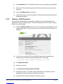
3.1.1 Start the Create Site Wizard............................................................................... 18
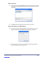
3.1.2 Optional - Use an Existing AP Configuration...................................................... 19
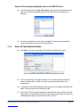
3.1.3 Optional - Load an AP Configuration File........................................................... 20
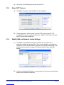
3.1.4 Enter AP Identification Details............................................................................ 22
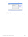
3.1.5 Select NTP Servers............................................................................................ 23
3.1.6 Modify NAS and Network Listen Settings........................................................... 23
3.2 Apply an Attribute Configuration to the AP ...................................................... 25

nano3G AP Installation Manual Contents
N3G_INST_300 v8.1 for N3G_2.0.5 © ip.access Limited 2011 Page ii
4 Configuration File Preparation ........................................................... 26
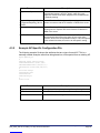
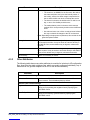
4.1 Overview of Attribute Configuration Files......................................................... 26
4.1.1 Attribute Types and Values ................................................................................ 27
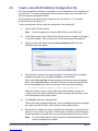
4.2 Create a nano3G AP Attribute Configuration File............................................ 28
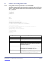
4.3 Example AP Configuration Files ...................................................................... 29
4.3.1 Example Generic Template File for nano3G S4 AP........................................... 29
4.3.2 Example AP-Specific Configuration File............................................................. 30
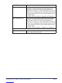
4.3.3 Other Attributes .................................................................................................. 31
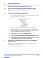
5 Commission a nano3G AP.................................................................. 33
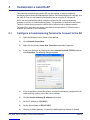
5.1 Configure a Commissioning Terminal to Connect to the AP............................ 33
5.2 Start Up the AP ................................................................................................ 34
5.2.1 Start up a nano3G S4 or S8 AP ......................................................................... 34
5.2.2 Start up a nano3G E8 AP................................................................................... 34
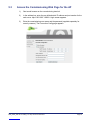
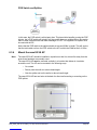
5.3 Access the Commissioning Web Page for the AP ........................................... 35
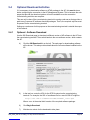
5.4 Optional Download Activities ........................................................................... 36
5.4.1 Optional - Software Download............................................................................ 36
5.4.2 Optional - ATAS Download ................................................................................ 37
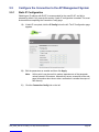
5.5 Configure the Connection to the AP Management System ............................. 38
5.5.1 Static IP Configuration........................................................................................ 38
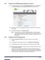
5.5.2 Configure the AP Management System Connection.......................................... 39
5.5.3 Complete the AP Commissioning....................................................................... 39
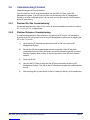
5.6 Commissioning Finished.................................................................................. 40
5.6.1 Finished On Site Commissioning ....................................................................... 40
5.6.2 Finished Advance Commissioning ..................................................................... 40
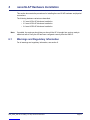
6 nano3G AP Hardware Installation ...................................................... 41
6.1 Warnings and Regulatory Information ............................................................. 41
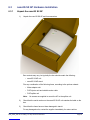
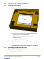
6.2 nano3G S4 AP Hardware Installation .............................................................. 42
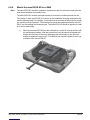
6.2.1 Unpack the nano3G S4 AP ................................................................................ 42
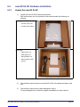
6.2.2 Commission the nano3G S4 AP......................................................................... 43
6.2.3 Cable Connections ............................................................................................. 43
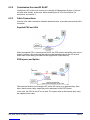
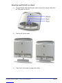
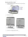
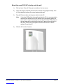
6.2.4 Mount the nano3G S4 AP .................................................................................. 44
6.3 nano3G S8 AP Hardware Installation .............................................................. 48
6.3.1 Unpack the nano3G S8 AP ................................................................................ 48
6.3.2 Commission the nano3G S8 AP......................................................................... 49
6.3.3 Cable Connections ............................................................................................. 49
6.3.4 Mount the nano3G S8 AP .................................................................................. 50
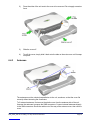
6.4 nano3G E8 AP Hardware Installation .............................................................. 54
6.4.1 Unpack the nano3G E8 AP ................................................................................ 54
6.4.2 Removable Cable and Antenna Covers ............................................................. 54
6.4.3 Antennas ............................................................................................................ 55
6.4.4 Commission the nano3G E8 AP......................................................................... 56
6.4.5 Cable Connections ............................................................................................. 56
6.4.6 Mount the nano3G E8 AP on a Wall .................................................................. 58
7 Finalize Installation.............................................................................. 62

nano3G AP Installation Manual
N3G_INST_300 v8.1 for N3G_2.0.5 © ip.access Limited 2011 Page iii
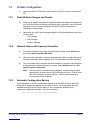
7.1 Check and Upgrade the nano3G AP Software Image ..................................... 62
7.1.1 Check the Current Software Image Version....................................................... 62
7.1.2 Download the Latest Software Image from the AP Management System to the AP
62
7.2 Finalize Configuration ...................................................................................... 64
7.2.1 Final Attribute Changes and Checks.................................................................. 64
7.2.2 Network Listen and Frequency Correction ......................................................... 64
7.2.3 Automatic Configuration Backup ........................................................................ 64
7.3 Bring the AP into Service ................................................................................. 65
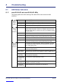
8 Troubleshooting .................................................................................. 66
8.1 LED Status Indicators ...................................................................................... 66
8.1.1 nano3G S4 AP and nano3G S8 AP LEDs.......................................................... 66
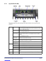
8.1.2 nano3G E8 AP LEDs.......................................................................................... 67
8.2 Backhaul Network Connection Problems......................................................... 68
8.3 nano3G E8 AP Does Not Start Up................................................................... 68
8.4 Factory Reset................................................................................................... 69
8.4.1 nano3G S4 AP and nano3G S8 AP Factory Reset ............................................ 69
8.4.2 nano3G E8 AP Factory Reset ............................................................................ 70
9 nano3G AP and PSU Regulatory Information ................................... 71
9.1 Warnings and Cautions.................................................................................... 71
9.2 Regulatory Statements for nano3G S4 AP ...................................................... 73
9.2.1 US FCC Compliance .......................................................................................... 73
9.2.2 Safety Standards................................................................................................ 73
9.3 Regulatory Statements for nano3G S8 AP ...................................................... 74
9.3.1 US FCC Compliance .......................................................................................... 74
9.3.2 EU Regulatory Compliance ................................................................................ 74
9.3.3 Safety Standards................................................................................................ 75
9.4 Regulatory Statements for nano3G E8 AP ...................................................... 76
9.4.1 US FCC Compliance .......................................................................................... 76
9.4.2 EU Regulatory Compliance ................................................................................ 76
9.4.3 Safety Standards................................................................................................ 76
9.4.4 Environmental Standards ................................................................................... 77

nano3G AP Installation Manual Introduction
N3G_INST_300 v8.1 for N3G_2.0.5 © ip.access Limited 2011 Page 1
1 Introduction
The ip.access nano3G AP is an indoor Access Point for enterprise applications.
This manual provides all the necessary information required to install an ip.access nano3G
AP. The manual provides step-by-step instructions for hardware installation and
configuration steps required to bring a nano3G AP into service.
The AP can be configured with a static IP address or it can obtain an IP address
dynamically via DHCP. The AP-AC connection can be configured to be secure (via IPSec
and a security gateway) or unsecured.
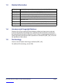
1.1 Overview
This manual is organised as follows:
• AP installation requirements
• AP configuration preparation
• AP hardware installation
• Commissioning configuration, for initial connection to an AC
• Configuration from the OMC-R
• Installation troubleshooting
• Regulatory warnings and safety information
• Supplementary information on licensing
1.2 User Requirements
It is assumed that any readers that will use the OMC-R Client already know how to:
• Start the OMC-R Client
• Navigate the Explorer Pane to find an AP object
Refer to [OPM_410] for information on using the OMC-R Client.

nano3G AP Installation Manual Introduction
N3G_INST_300 v8.1 for N3G_2.0.5 © ip.access Limited 2011 Page 2
1.3 Related Information
1.4 Licenses and Copyright Notices
Portions of the AP are constructed from third-party software and open source code and
ip.access ltd gratefully acknowledges the contributions that these libraries, technologies
and components have made to the product. Each of these is supplied under the terms of a
license agreement and these are either reproduced or referenced in [REF_300], in line with
the stipulations of their authors.
1.5 Terminology
Common nano3G System terminology is defined in [REF_105].
For additional 3G terminology, see [21.905].
[INST_440] nano3G AP Management System Installation Manual (N3G_INST_430)
[OPM_300] nano3G AP Operations Manual (N3G_OPM_300)
[OPM_410] 3G OMC-R Client Operations Manual (N3G_OPM_410)
[OPM_440] nano3G AP Management System Operations Manual (N3G_OPM_440)
[REF_105] nano3G System Glossary (N3G_REF_105)
[REF_110] nano3G System Configuration Management (CM) MIB Reference Manual
(N3G_REF_110)
[REF_300] nano3G AP License and Copyright Reference (N3G_REF_300)
[21.905] Vocabulary for 3GPP Specifications (3GPP 3G TR 21.905)

nano3G AP Installation Manual Installation Overview and Requirements
N3G_INST_300 v8.1 for N3G_2.0.5 © ip.access Limited 2011 Page 3
2 Installation Overview and Requirements
2.1 Installation Tasks
There are three basic tasks that must be completed to install a nano3G AP and make it
ready to provide service:
• Pre-Provisioning
• Commissioning
• Site installation
These tasks can be completed in any order. In most cases, however, the most practical
approach is to provision and commission an AP before final site installation.
2.1.1 Pre-Provisioning
Configure a nano3G AP with the information it needs to allow it to provide service, such as
a serving AC address, neighbour lists, operating frequency and network identity details. As
an AP’s configuration is stored on its serving AP Management System, an AP can be
pre-provisioned at any time. This offers maximum flexibility for pre-provisioning an AP as far
or as little ahead of site installation as is needed.
It is recommended to perform at least some pre-provisioning for an AP before on site
installation. As a minimum, use the Create Site Wizard in the OMC-R Client to create a site
and AP object on the serving AP Management System that will contain the AP’s
configuration. If an AP attempts to connect to its serving AP Management System, but the
AP Management System has not yet been provisioned with site details for the AP, the AP
Management System will raise alarms about attempts to connect by an unknown AP.
For more information about AP pre-provisioning, see 3 Pre-Provisioning a nano3G AP.
2.1.2 Commissioning
Use the nano3G AP’s built-in configuration web page to configure the AP with the settings it
needs to establish a connection with its serving AP Management System.
This is done using a commissioning terminal, either before sending the AP out for
installation or on site using a suitably prepared laptop.
The benefits of commissioning an AP before sending on site are:
• The site installation engineer does not need a commissioning laptop.
• By corollary, the site installation engineer does not need to know the user name
and password for the AP commissioning web page.
• If the AP has been properly pre-provisioned, the AP is effectively plug-and-play.
• By corollary, a nano3G S4 AP or nano3G S8 AP could be installed by an end
customer, without help from a site installation engineer. The customer simply
needs to provide suitable network and power connections.
Note: Due to the physical installation requirements of a nano3G E8 AP, which must be securely
wall mounted, it is recommended that an E8 AP is installed by a suitably qualified site
installation engineer.
The benefits of using a laptop for commissioning an AP on site are:

nano3G AP Installation Manual Installation Overview and Requirements
N3G_INST_300 v8.1 for N3G_2.0.5 © ip.access Limited 2011 Page 4
• If there is a commissioning error, this can be corrected immediately without
needing to return the AP
• If an AP has been in storage for some time, the required software build and/or
ATAS package can be installed on the AP in situ
2.1.3 On Site Installation
Physical installation of a nano3G AP at its operating site, including providing the AP with
power and a suitable network connection that provides a backhaul path to the AP
Management System and AC.
If a nano3G AP has been enabled for service prior to the site visit, the installation engineer
can make test calls immediately.

nano3G AP Installation Manual Installation Overview and Requirements
N3G_INST_300 v8.1 for N3G_2.0.5 © ip.access Limited 2011 Page 5
2.2 Requirements for All nano3G APs
This applies to all nano3G APs.
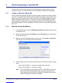
2.2.1 General Requirements
All nano3G AP models have the following general requirements for installation:
• A commissioning terminal, which can be either a desktop computer or a laptop,
with:
• OS: Windows XP
• Web browser: Microsoft Internet Explorer 7
• JavaScript enabled in the web browser
• A short Ethernet cable for connecting the commissioning terminal to the AP
• A temporary means to provide power to the AP while it is connected to the
commissioning terminal
• A permanent means to provide power to the AP once it is connected to the
backhaul
• An Ethernet connection to the backhaul via CAT5 Ethernet cabling
• Access to a DNS service on the backhaul to resolve symbolic addresses
• Access to an NTP service on the backhaul to set the correct time and date - NTP
servers must be chosen from a list of known NTP servers configured in the OMC-R
• If a firewall is in place on the network an AP will use for backhaul, this must be
configured to allow traffic to and from the AP - see the port usage section below
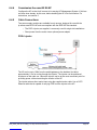
Port Usage
All connections are outgoing. That is, they are initiated from the AP. Port usage has some
dependency on whether or not the AP is using IPsec.
With IPSec, the standard two ports are used:
Without IPSec, the following ports are used:
Protocol Destination Port Use
udp 500 IPSec initial connection
udp 4500 IPSec operations
Protocol Destination Port Use
tcp 3052 SOIP connection to AC
udp 3000 CS RTP to AC
udp 3001 CS RTCP to AC
udp 3002 CS Mux to AC
udp 5000 PS RTP to AC
udp 5001 PS RTCP to AC
udp 5002 PS Mux to AC

nano3G AP Installation Manual Installation Overview and Requirements
N3G_INST_300 v8.1 for N3G_2.0.5 © ip.access Limited 2011 Page 6
The following ports are also used. When IPsec is used, they may be inside or outside the
IPSec tunnel, depending on configuration:
2.2.2 Information Required for Pre-Provisioning
All nano3G AP models require the configuration details listed in this section. This
information will be used to configure an AP from the OMC-R Client, typically by a NOC
engineer.
• User name and password for the OMC-R Client. To be able to configure an AP
from the OMC-R Client, the user name must have Full Access to the AP
Management System serving the AP and Full Access granted to its APs. See
[OPM_410] for full details about user permissions.
• The minimum set of configuration data for the AP is:
• Cell ID (also used as the ID of this AP on the serving nano3G AC)
• IP Address or FQDN of the serving AC
• MCC
•MNC
•LAC
•RAC
•SAI SAC
•SAI LAC
•UARFCN
• Scrambling code
• RNC ID
• RSSI scan bands
• Latitude and longitude of the APs installation site, for RANAP location
reporting
• Additional configuration that may be required includes:
• Static neighbour list - see [OPM_300] for neighbour list configuration
• URLs for the PM reporting and diagnostic services on the AP Management
System
Note: It is possible to configure an AP before taking it on site.
Protocol Destination Port Use
tcp 80 PM upload, software download, CRL download
tcp 443 PM upload, software download, CRL download
udp 53 DNS
udp 67 DHCP - not needed for static IP configuration
udp 68 DHCP - not needed for static IP configuration
udp 123 NTP

nano3G AP Installation Manual Installation Overview and Requirements
N3G_INST_300 v8.1 for N3G_2.0.5 © ip.access Limited 2011 Page 7
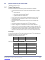
2.2.3 Configuration Files - Optional
An initial configuration file can be used to rapidly configure the AP via the OMC-R Create
Site Wizard. This is an alternative to using settings from an existing AP. Additional
configuration files can be loaded against the AP object after it has been created by the
Create Site Wizard. If they will be used, the location of any configuration files must be
known.
When using configuration files, it is recommended, as a minimum, to create a generic
configuration file that contains attribute settings that are common to all APs in the network.
Optionally create a separate attributes file for each AP to be commissioned.
Configuration files are describe in section 4.
2.2.4 Optional Items for Commissioning
The optional items in this section can only be used if the commissioning terminal is running
a web server that provides a path to any ip.access AP software download packages. That
is, the required .sdp files must be present on the commissioning terminal.
Setting up a web server for this purpose on the commissioning terminal is outside the scope
of this manual.
Software Image
If there is a requirement to update the AP’s software during commissioning, the relevant
.sdp file must be present on the commissioning terminal.
ATAS File
If there is a requirement to update the AP’s security certificates during commissioning, the
relevant .sdp file containing the ATAS package must be present on the commissioning
terminal.
2.2.5 Information Required for Commissioning
All nano3G AP models require the configuration details listed in this section. This
information will be to commission an AP from the commissioning terminal, so that the AP
can subsequently connect to its serving AP Management System.
It is possible to commission an AP before taking it on site.
For connecting to the AP from the commissioning terminal:
• User name and password for the AP web server - if necessary, contact customer
support at ip.access for the current user name and password
For commissioning the AP:
• IP Address or FQDN of the serving AP Management System
• IP Address or FQDN of an NTP server
• DHCP or static IP
• If static IP is required:
• IP address for the AP

nano3G AP Installation Manual Installation Overview and Requirements
N3G_INST_300 v8.1 for N3G_2.0.5 © ip.access Limited 2011 Page 8
•Netmask
• IP Address or FQDN of the default gateway
• IP Address or FQDN of the Primary DNS
• IPSec is optional, but if IPSec is required:
• IP Address or FQDN of the IPsec Security Gateway
• IP Address or FQDN of a CRL server
• Optionally, Traffic Selector information (IP address and subnet mask)
A traffic selector defines a range of IP addresses that are sent through the
IPSec tunnel. This allows an extra degree of control over the traffic that is
passed down the IPSec tunnel. Normally, the security gateway controls this
range and no other configuration is needed.

nano3G AP Installation Manual Installation Overview and Requirements
N3G_INST_300 v8.1 for N3G_2.0.5 © ip.access Limited 2011 Page 9
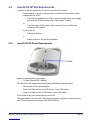
2.3 nano3G S4 AP Site Requirements
The nano3G S4 APs are typically installed in retail or small office environments. In
summary, each AP will require:
• Power supplied in one of the following ways:
• From the mains adaptor unit supplied with the AP, which requires a suitable
mains power supply point near the AP that is within reach of the adaptor’s
cabling
or
• From the supplied POE splitter, which requires a Power over Ethernet
connection to the splitter
• A site for the AP:
• Wall mount location
or
• Stable surface for free standing installation
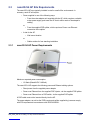
2.3.1 nano3G S4 AP Power Requirements
Maximum expected power consumption:
• 13 Watts (Rated 9VDC 1450mA)
The nano3G S4 AP supports the following power and Ethernet cabling options:
• Direct power from the supplied power adapter
• Power over Ethernet from the supplied POE injector, via the supplied POE splitter
• Power over Ethernet from a POE switch, via the supplied POE splitter
A POE cable must not be inserted directly into the AP.
The power adapter, as well as the POE inserter and splitter supplied by ip.access comply
with LPS requirements in accordance with IEC/EN 60950-1.

nano3G AP Installation Manual Installation Overview and Requirements
N3G_INST_300 v8.1 for N3G_2.0.5 © ip.access Limited 2011 Page 10
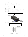
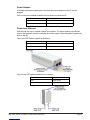
Power Adapter
A suitable mains power supply point into which the power adapter for the AP can be
plugged.
Only use the power adapter supplied by ip.access to power the AP:
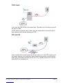
Power over Ethernet
POE requires the use of a power inserter and a splitter. The power inserter is positioned
close to the backhaul network connection and mains supply, while the splitter is positioned
close to the AP.
This is the POE inserter supplied by ip.access:
Only use the POE splitter supplied by ip.access:
ip.access part number EPS1173R
Input 100-240V ~ 50/60Hz 0.7A
Output +9VDC 1.67A
ip.access part number 109A
Input 100/230V ~ 60/50Hz 0.5/0.25A
Output 48VDC 0.38A
ip.access part number 222A
Input 48VDC 0.35A
Output 9VDC 1.33A

nano3G AP Installation Manual Installation Overview and Requirements
N3G_INST_300 v8.1 for N3G_2.0.5 © ip.access Limited 2011 Page 11
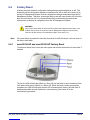
2.3.2 nano3G S4 AP Physical Requirements
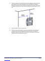
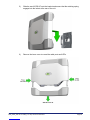
A nano3G S4 AP may be installed in one of the following ways (see section 6.2.4):
• Free-standing on a flat stable surface.
• Attached to a wall or partition using two screws that engage in keyhole slots in the
rear surface of the AP.
• Attached to a POE splitter using the two screws that engage in keyhole slots in the
rear surface of the AP. The POE splitter in turn attaches to a wall or partition using
two screws.
The unit must be vertical to ensure that air can circulate freely around it.
It is recommended to install the AP with its front surface facing the area requiring cellular
coverage, unobstructed by walls or partitions that may have significant RF attenuation.
2.3.3 nano3G S4 AP IP Bandwidth Requirements
At maximum capacity, a nano3G S4 AP will require:
• Downlink: at least 5Mbps
• Uplink: at least 512Kbps
This will deliver up to 4 voice calls and HSDPA services up to 3.6Mbps.
2.3.4 nano3G S4 AP Sundry Installation Equipment
• To mount the POE splitter or the nano3G S4 AP onto the wall:
• 2 self tapping pan head screws, size No. 6 (approx 3.5mm (0.14in) in
diameter)
• Wall plugs if required
• Suitable drills and screwdriver
Dimensions and
weight
Height 176mm (without stand)
193mm (with stand)
Width 170mm
Depth 51mm
Approximate Weight 0.42 kg (AP only)
Environmental Cooling Vents on the back at top and bottom
Operating Temperature 0°C to 40°C
Operating Humidity 10 to 70% non-condensing

nano3G AP Installation Manual Installation Overview and Requirements
N3G_INST_300 v8.1 for N3G_2.0.5 © ip.access Limited 2011 Page 12
2.4 nano3G S8 AP Site Requirements
In addition to the site requirements for all APs, each S8 AP will require:
• Power supplied in one of the following ways, according to the accessory unit(s)
supplied with the S8 AP:
• From the mains adaptor unit, which requires a suitable mains power supply
point near the AP that is within reach of the adaptor’s cabling
or
• From the supplied POE splitter, which requires a Power over Ethernet
connection to the splitter
• A site for the AP:
• Wall mount location
or
• Stable surface for free standing installation
2.4.1 nano3G S8 AP Power Requirements
Maximum expected power consumption:
• 13 Watts (Rated 9VDC 1450mA)
The nano3G S8 AP supports the following power and Ethernet cabling options:
• Direct power from the power adapter
• Power over Ethernet from the POE injector, via the POE splitter
• Power over Ethernet from a POE switch, via the POE splitter
A POE cable must not be inserted directly into the AP.
The power adapter, as well as the POE inserter and splitter supplied by ip.access comply
with LPS requirements in accordance with IEC/EN 60950-1.

nano3G AP Installation Manual Installation Overview and Requirements
N3G_INST_300 v8.1 for N3G_2.0.5 © ip.access Limited 2011 Page 13
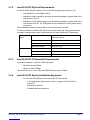
Power Adapter
A suitable mains power supply point into which the power adapter for the AP can be
plugged.
Only use the power adapter available from ip.access to power the AP:
Power over Ethernet
POE requires the use of a power inserter and a splitter. The power inserter is positioned
close to the backhaul network connection and mains supply, while the splitter is positioned
close to the AP.
This is the POE inserter supplied by ip.access:
Only use the POE splitter available from ip.access:
ip.access part number PSA15R-090PV-R
Input 100-240V ~ 50/60Hz 0.5A
Output +9VDC 1.67A
ip.access part number 236
Input 100/240V ~ 60/50Hz 0.5A
Output 48VDC 0.35A
ip.access part number 222A
Input 48VDC 0.35A
Output 9VDC 1.33A

nano3G AP Installation Manual Installation Overview and Requirements
N3G_INST_300 v8.1 for N3G_2.0.5 © ip.access Limited 2011 Page 14
2.4.2 nano3G S8 AP Physical Requirements
A nano3G S8 AP may be installed in one of the following ways (see section 6.3.4):
• Free-standing on a flat stable surface.
• Attached to a wall or partition using two screws that engage in keyhole slots in the
rear surface of the AP.
• Attached to a POE splitter using the two screws that engage in keyhole slots in the
rear surface of the AP. The POE splitter in turn attaches to a wall or partition using
two screws.
The unit must be vertical to ensure that air can circulate freely around it.
It is recommended to install the AP with its front surface facing the area requiring cellular
coverage, unobstructed by walls or partitions that may have significant RF attenuation.
2.4.3 nano3G S8 AP IP Bandwidth Requirements
At maximum capacity, a nano3G S8 AP will require:
• Downlink: at least 7Mbps
• Uplink: at least 1Mbps
This will deliver up to 8 voice calls and HSDPA services up to 7.2 Mbps.
2.4.4 nano3G S8 AP Sundry Installation Equipment
• To mount the POE splitter or the nano3G S8 AP onto the wall:
• 2 self tapping pan head screws, size No. 6 (approx 3.5mm (0.14in) in
diameter)
• Wall plugs if required
• Suitable drills and screwdriver
Dimensions and
weight
Height 176mm (without stand)
193mm (with stand)
Width 170mm
Depth 51mm
Approximate Weight 0.42 kg (AP only)
Environmental Cooling Vents on the back at top and bottom
Operating Temperature 0°C to 40°C
Operating Humidity 10 to 70% non-condensing

nano3G AP Installation Manual Installation Overview and Requirements
N3G_INST_300 v8.1 for N3G_2.0.5 © ip.access Limited 2011 Page 15
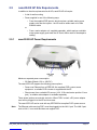
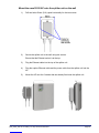
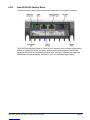
2.5 nano3G E8 AP Site Requirements
In addition to the site requirements for all APs, each E8 AP will require:
• A site for wall mounting
• Power supplied in one of the following ways:
• From the supplied POE injector, which requires a suitable mains power
supply point near the injector - the AP must be within reach of a 100m
Ethernet cable
or
• From a mains adaptor unit, supplied separately, which requires a suitable
mains power supply point near the AP that is within reach of the adaptor’s
cabling
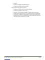
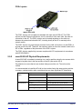
2.5.1 nano3G E8 AP Power Requirements
Maximum expected power consumption:
• 20 Watts (Rated +12V or -48V DC)
The nano3G E8 AP supports the following power options:
• Power over Ethernet from a IEEE 802.3at compliant POE+ power source
equipment - a suitable POE+ inserter is supplied with the AP
• Direct power from a suitable DC source (+12V, 2.5A rated centre positive 2.1mm
jack) - a suitable mains adaptor is available separately
These power options are mutually exclusive. When POE+ is used, a DC power adapter
must not be plugged in to the AP and vice versa.
The nano3G E8 AP can be used with any IEEE 802.3at compliant POE+ power source.
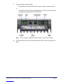
Note: The Ethernet cable carrying POE+ must be plugged into the LAN 1 port. The LAN 2 port,
next to LAN 1, is not used and does not support POE.
Page is loading ...
Page is loading ...
Page is loading ...
Page is loading ...
Page is loading ...
Page is loading ...
Page is loading ...
Page is loading ...
Page is loading ...
Page is loading ...
Page is loading ...
Page is loading ...
Page is loading ...
Page is loading ...
Page is loading ...
Page is loading ...
Page is loading ...
Page is loading ...
Page is loading ...
Page is loading ...
Page is loading ...
Page is loading ...
Page is loading ...
Page is loading ...
Page is loading ...
Page is loading ...
Page is loading ...
Page is loading ...
Page is loading ...
Page is loading ...
Page is loading ...
Page is loading ...
Page is loading ...
Page is loading ...
Page is loading ...
Page is loading ...
Page is loading ...
Page is loading ...
Page is loading ...
Page is loading ...
Page is loading ...
Page is loading ...
Page is loading ...
Page is loading ...
Page is loading ...
Page is loading ...
Page is loading ...
Page is loading ...
Page is loading ...
Page is loading ...
Page is loading ...
Page is loading ...
Page is loading ...
Page is loading ...
Page is loading ...
Page is loading ...
Page is loading ...
Page is loading ...
Page is loading ...
Page is loading ...
Page is loading ...
Page is loading ...
-
 1
1
-
 2
2
-
 3
3
-
 4
4
-
 5
5
-
 6
6
-
 7
7
-
 8
8
-
 9
9
-
 10
10
-
 11
11
-
 12
12
-
 13
13
-
 14
14
-
 15
15
-
 16
16
-
 17
17
-
 18
18
-
 19
19
-
 20
20
-
 21
21
-
 22
22
-
 23
23
-
 24
24
-
 25
25
-
 26
26
-
 27
27
-
 28
28
-
 29
29
-
 30
30
-
 31
31
-
 32
32
-
 33
33
-
 34
34
-
 35
35
-
 36
36
-
 37
37
-
 38
38
-
 39
39
-
 40
40
-
 41
41
-
 42
42
-
 43
43
-
 44
44
-
 45
45
-
 46
46
-
 47
47
-
 48
48
-
 49
49
-
 50
50
-
 51
51
-
 52
52
-
 53
53
-
 54
54
-
 55
55
-
 56
56
-
 57
57
-
 58
58
-
 59
59
-
 60
60
-
 61
61
-
 62
62
-
 63
63
-
 64
64
-
 65
65
-
 66
66
-
 67
67
-
 68
68
-
 69
69
-
 70
70
-
 71
71
-
 72
72
-
 73
73
-
 74
74
-
 75
75
-
 76
76
-
 77
77
-
 78
78
-
 79
79
-
 80
80
-
 81
81
-
 82
82


ip.access QGGIPA237B User manual
- Type
- User manual
- This manual is also suitable for
Ask a question and I''ll find the answer in the document
Finding information in a document is now easier with AI
Related papers


Other documents
-
Alcatel-Lucent OmniPCX Office RCE Compact Installation guide
-
-
Multitech OmniPCX Office Installation guide
-
-
Ruckus Wireless ZoneFlex 7352 User manual
-
-
Motorola AP-7131N-FGR Specification
-
Dell W-3200 User guide
-
-