Page is loading ...

SINCE
1906
SINCE
1906
Manual Insert
PHONE: (360) 734-1540 • www.southbendlathe.com
MODEL SB1114F HEAVY 13®
13" X 30" EVS LATHE w/DRO
Copyright © February, 2021 by South Bend Lathe Co., Revised December, 2021 (CS)
WARNING: No portion of this manual may be reproduced without written approval.
#CS21577 Printed in Taiwan
The Model SB1114F lathe is the same machine as the Model SB1051 except for the following:
• Model SB1114F requires single-phase, hardwired power supply.
• Added a 2-Axis Fagor Digital Readout (DRO).
• The distance between centers is 30".
• Includes 8 cast iron leveling pads.
Except for the differences noted in this insert, all other content in the Model SB1051 Owner’s Manual
applies to this machine. Before operating your new lathe, you MUST read and understand this insert,
the entire Model SB1051 Owner’s Manual, and the Fagor DRO Owner’s Manual to reduce the risk of
injury when using this machine. Keep this insert for later reference.
If you have any further questions about this manual insert or the differences between the Model
SB1114F and the Model SB1051, contact our Technical Support at (360) 734-1540 or email
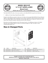
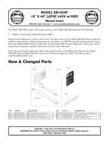
New 2-Axis Fagor DRO
Figure Figure 1. Location of new DRO.. Location of new DRO.
FagorFagor
2-Axis DRO2-Axis DRO
V2.12.21

-2-
For Machines Mfd. Since 1/21
Model SB1114F INTRODUCTION
Product Specifications
Model SB1114F Page 1 of 4
Model SB1114F
13" x 30" EVS Lathe with DRO
Product Dimensions
Weight........................................................................................................................................................... 2029 lbs.
Width (side-to-side) x Depth (front-to-back) x Height............................................................... 71 x 38 x 60-1/2 in.
Footprint (Length x Width)........................................................................................................... 68-1/2 x 19-1/2 in.
Shipping Dimensions
Type.......................................................................................................................................................... Wood Crate
Content.......................................................................................................................................................... Machine
Weight........................................................................................................................................................... 2602 lbs.
Length x Width x Height................................................................................................................... 79 x 38 x 77 in.
Electrical
Power Requirement......................................................................................................... 220V, Single-Phase, 60 Hz
Full-Load Current Rating................................................................................................................................. 20.5A
Minimum Circuit Size.......................................................................................................................................... 30A
Connection Type.................................................................................................. Permanent (Hardwire to Shutoff)
Switch Type....................................................................................... Control Panel w/Magnetic Switch Protection
Inverter (VFD) Type.................................................................................................................... Yaskawa G7A25P5
Inverter (VFD) Size......................................................................................................................................... 7.5 HP
Recommended Phase Converter...................................................................................................................... G7978
Motors
Main
Horsepower............................................................................................................................................... 5 HP
Phase.................................................................................................................................................... 3-Phase
Amps........................................................................................................................................................ 15.5A
Speed........................................................................................................................................... 0 - 4500 RPM
Type........................................................................................................................................ TEFC Induction
Power Transfer .......................................................................................................................................... Belt
Bearings................................................................................................ Shielded & Permanently Lubricated
Coolant Pump
Horsepower............................................................................................................................................ 1/8 HP
Phase............................................................................................................................................ Single-Phase
Amps........................................................................................................................................................ 0.23A
Speed................................................................................................................................................ 3400 RPM
Type........................................................................................................................ TEFC Induction (Class E)
Power Transfer ...................................................................................................................................... Direct
Bearings................................................................................................ Shielded & Permanently Lubricated
Product Specifications
P.O. Box 2027, Bellingham, WA 98227 U.S.A.
www.southbendlathe.com
PHONE: (360) 734-1540 • © South Bend Lathe Co.

For Machines Mfd. Since 1/21 Model SB1114F
-3-
INTRODUCTION
Model SB1114F Page 2 of 4
Oil Pump
Horsepower............................................................................................................................................ 1/4 HP
Phase............................................................................................................................................ Single-Phase
Amps.......................................................................................................................................................... 1.3A
Speed................................................................................................................................................ 1720 RPM
Type........................................................................................................................................ TEFC Induction
Power Transfer ...................................................................................................................................... Direct
Bearings................................................................................................ Shielded & Permanently Lubricated
Main Specifications
Operation Info
Swing Over Bed................................................................................................................................. 13-1/4 in.
Distance Between Centers...................................................................................................................... 30 in.
Max Weight Between Centers............................................................................................................. 132 lbs.
Swing Over Cross Slide............................................................................................................................. 8 in.
Swing Over Saddle.................................................................................................................................. 13 in.
Maximum Tool Bit Size.......................................................................................................................... 5/8 in.
Compound Travel................................................................................................................................ 3-3/4 in.
Carriage Travel................................................................................................................................ 25-9/16 in.
Cross Slide Travel...................................................................................................................................... 7 in.
Headstock Info
Spindle Bore.......................................................................................................................................... 1.65 in.
Spindle Taper.......................................................................................................................................... MT#5
Number of Spindle Speeds................................................................................................................. Variable
Spindle Speeds........................................................................................................................ 100 - 3000 RPM
Spindle Type.............................................................................................................................. D1-5 Camlock
Spindle Bearings................................................................................................ NSK or NTN Tapered Roller
Spindle Length.................................................................................................................................. 20-7/8 in.
Spindle Length with 3-Jaw Chuck................................................................................................... 26-3/8 in.
Spindle Length with 4-Jaw Chuck................................................................................................... 26-3/8 in.
Spindle Length with Faceplate......................................................................................................... 22-1/2 in.
Tailstock Info
Tailstock Quill Travel.......................................................................................................................... 4-1/2 in.
Tailstock Taper........................................................................................................................................ MT#3
Tailstock Barrel Diameter.................................................................................................................. 1.968 in.
Threading Info
Number of Longitudinal Feeds..................................................................................................................... 17
Range of Longitudinal Feeds.......................................................................................... 0.002 - 0.067 in./rev.
Number of Cross Feeds................................................................................................................................. 17
Range of Cross Feeds...................................................................................................... 0.001 - 0.034 in./rev.
Number of Inch Threads............................................................................................................................... 45
Range of Inch Threads..................................................................................................................... 2 - 72 TPI
Number of Metric Threads........................................................................................................................... 39
Range of Metric Threads............................................................................................................ 0.2 - 14.0 mm
Number of Modular Pitches.......................................................................................................................... 18
Range of Modular Pitches............................................................................................................. 0.3 - 3.5 MP
Number of Diametral Pitches....................................................................................................................... 21
Range of Diametral Pitches.............................................................................................................. 8 - 44 DP

-4-
For Machines Mfd. Since 1/21
Model SB1114F INTRODUCTION
Model SB1114F Page 3 of 4
Dimensions
Bed Width.................................................................................................................................................. 9 in.
Carriage Leadscrew Diameter............................................................................................................ 1-1/8 in.
Leadscrew TPI......................................................................................................................................... 4 TPI
Carriage Leadscrew Length.................................................................................................................... 47 in.
Steady Rest Capacity.................................................................................................................. 3/8 - 5-1/2 in.
Follow Rest Capacity................................................................................................................... 5/8 - 2-7/8 in.
Faceplate Size.......................................................................................................................................... 10 in.
Feed Rod Diameter................................................................................................................................. 3/4 in.
Floor to Center Height...................................................................................................................... 42-1/4 in.
Height With Leveling Jacks.......................................................................................................... 60-15/16 in.
Construction
Base.................................................................................................................................................... Cast Iron
Headstock.......................................................................................................................................... Cast Iron
End Gears.......................................................................................................................................... Cast Iron
Bed................................................................ Induction-Hardened, Precision-Ground, Meehanite Cast Iron
Body................................................................................................................................................... Cast Iron
Stand.................................................................................................................................................. Cast Iron
Paint Type/Finish.............................................................................................................................. Urethane
Fluid Capacities
Headstock Capacity.............................................................................................................................. 21.7 qt.
Headstock Fluid Type....................................................... ISO 32 (e.g., Grizzly T23963, Mobile DTE Light)
Gearbox Capacity.................................................................................................................................... 1.4 qt.
Gearbox Fluid Type.............................................................. ISO 68 (e.g., Grizzly T23962, Mobile Vactra 2)
Apron Capacity....................................................................................................................................... 1.2 qt.
Apron Fluid Type.................................................................. ISO 68 (e.g., Grizzly T23962, Mobile Vactra 2)
Coolant Capacity................................................................................................................................... 11.1 qt.
Other
Country of Origin ........................................................................................................................................... Taiwan
Warranty ........................................................................................................................................................ 2 Years
Approximate Assembly & Setup Time ......................................................................................................... 2 Hours
Serial Number Location .............................................................................................................................. ID Label
Features
Allen Bradley Electrical Components
Signature South Bend 3 V-Way Bed
Safety Chuck Guard with Micro-Switch Shut-Off
Halogen Work Light
4-Way Tool Post
Complete Recycling Coolant System
Meehanite Castings with Induction-Hardened Ways
Micrometer Carriage Stop
Threading Dial Indicator
NSK or NTN Japanese Spindle Bearings
Full-Length Splash Guard with Rounded Corner
Yaskawa G7A25P5 Inverter
Front Removable Sliding Chip Tray
Completely Enclosed Universal Gearbox for Cutting Inch, Metric, Modular, and Diametral Pitches
Jog and Emergency Stop Buttons
Pressurized Lubrication System
Fagor DRO

For Machines Mfd. Since 1/21 Model SB1114F
-5-
PREPARATION
Power Supply
Requirements
Electrocution or fire may
occur if machine is not
correctly grounded and
attached to the power
supply. Use a qualified
electrician to ensure a safe
power connection.
Before installing the machine, consider the
availability and proximity of the required power
supply circuit. If an existing circuit does not meet
the requirements for this machine, a new circuit
must be installed.
To minimize the risk of electrocution, fire,
or equipment damage, installation work and
electrical wiring must be done by a
n electrician
or qualified service personnel
in accordance with
applicable electrical codes and safety standards.
Availability
The full-load current rating is the amperage
a machine draws at 100% of the rated output
power. On machines with multiple motors, this is
the amperage drawn by the largest motor or sum
of all motors and electrical devices that might
operate at one time during normal operations.
The full-load current is not the maximum
amount of amps that the machine will draw. If
the machine is overloaded, it will draw additional
amps beyond the full-load rating.
If the machine is overloaded for a sufficient
length of time, damage, overheating, or fire may
result—especially if connected to an undersized
circuit. To reduce the risk of these hazards,
avoid overloading the machine during operation
and make sure it is connected to a power supply
circuit that meets the requirements in the
following section.
Full-Load Current Rating
Full-Load Rating at 220V ................ 20.5 Amps
For your own safety and protection of property,
consult an electrician if you are unsure about
wiring practices or applicable electrical codes.
Note: The circuit requirements in this manual
are for
a dedicated circuit—where only one
machine will be running at a time. If this
machine will be connected to a shared circuit
where multiple machines will be running at
the same time, consult a qualified electrician to
ensure the circuit is properly sized.
A power supply circuit includes all electrical
equipment between the main breaker box or fuse
panel in your building and the incoming power
connections inside the machine. This circuit
must be safely sized to handle the full-load
current that may be drawn from the machine for
an extended period of time. (If this machine is
connected to a circuit protected by fuses, use a
time delay fuse marked D.)
Circuit Information
Circuit Requirements for 220V
This machine is prewired to operate on a power
supply circuit that has a verified ground and
meets the following requirements:
Nominal Voltage ..................... 220V/230V/240V
Cycle .............................................................60 Hz
Phase ..............................................Single-Phase
Circuit Rating....................................... 30 Amps

-6-
For Machines Mfd. Since 1/21
Model SB1114F PREPARATION
Grounding Requirements
This machine must be grounded! In the event
of
certain types of malfunctions or breakdowns,
grounding provides a path of least resistance
for electric current
in order to reduce the risk of
electric shock.
Power supply connections that are hardwired
to the power source must be connected to a
grounded metal permanent wiring system, or
to a system having an equipment-grounding
conductor.
Power Source
LOCKING
DISCONNECT SWITCH
Machine
Conduit
Ground Ground
Conduit
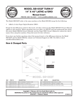
Figure Figure 2. Typical setup of a permanently connected . Typical setup of a permanently connected
machine.machine.
Connection Type
A permanently connected (hardwired) power
supply is typically installed with wires running
through mounted and secured conduit. A
disconnecting means, such as a locking switch
(see following figure) must be provided to
allow the machine to be disconnected (isolated)
from the power supply when required. This
installation must be preformed by an electrician
in accordance with all applicable electrical codes
and ordinances.
Serious injury could occur if you connect
the machine to power before completing the
setup process. DO NOT connect to power until
instructed later in this manual.
Extension Cords
Since this machine must be permanently
connected to the power supply, an extension cord
cannot be used.
Power Connection
Electrocution or fire
may occur if machine is
ungrounded, incorrectly
connected to power, or
connected to an undersized
circuit. Use a qualified
electrician to ensure a safe
power connection.
Once your machine is set up and assembled as
previously described in this manual, it is ready to
be connected to the power supply.
Hardwire setups require power supply lines to
be enclosed inside of conduit, which is securely
mounted and constructed in adherence to
applicable electrical codes.
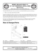
A hardwire setup for this machine must be
equipped with a locking disconnect switch
as a means to disconnect the power during
adjustments or maintenance, which is a typical
requirement for many lock-out/tag-out safety
programs. Figure 3 shows a simple diagram of a
hardwire setup with a locking disconnect switch
between the power supply and the machine.
Hardwiring to Power Supply
Due to the complexity required for planning,
bending, and installing the conduit necessary for
a code-compliant hardwire setup, an electrician
or other qualified person MUST perform this
type of installation.
Power Supply
Locking
Disconnect Switch Machine
Conduit Conduit
Figure Figure 3. Typical hardwire setup with a locking . Typical hardwire setup with a locking
disconnect switch.disconnect switch.

For Machines Mfd. Since 1/21 Model SB1114F
-7-
PREPARATION
Connecting Power Supply Wires
to Machine
Connecting power supply wires to machine
without first disconnecting power supply may
result in serious injury or death.
To connect power supply wires to machine:
1. DISCONNECT POWER SUPPLY WIRES
OR LOCK DISCONNECT SWITCH BOX IN
OFF POSITION!
2. Open the electrical cabinet.
3. Insert incoming power wires through strain
relief in electrical box (see Figure 4).
During next step, make sure incoming ground
wire is connected to grounding screw to
ensure machine will be properly grounded
(see "Ground Screw" in Figure 5). An
ungrounded or improperly grounded machine
can cause electrocution if live electrical
wires make contact with frame or other parts
touched by operator.
Figure Figure 4. Location of power supply strain relief.. Location of power supply strain relief.
Incoming Power Incoming Power
Strain ReliefStrain Relief
4. Connect ground wire to grounding screw,
then connect incoming power wires to top
of "1L1" and "3L2" terminals shown in
Figure 5.
— Make sure wires have enough slack inside
electrical cabinet so they are not pulled
tight or stretched.
5. Close electrical cabinet, connect power
supply to machine, and proceed to Test Run.
Figure Figure 5. Incoming ground and power wire terminals.. Incoming ground and power wire terminals.
IncomingIncoming
Power TerminalsPower Terminals
GroundGround
ScrewScrew
3L23L21L11L1

-8-
For Machines Mfd. Since 1/21
Model SB1114F PREPARATION
Correcting Phase Polarity
This sub-section is only provided for
troubleshooting 3-phase power connections. If
you discover during the test run that the that
the main motor runs backwards, the motor
connection may be wired "out of phase," meaning
that the polarity is incorrect as wired. This is a
common situation with 3-phase power, and it is
easy to correct.
To correct polarity of main motor power
connection:
1. DISCONNECT MACHINE FROM POWER!
Test Run
After all preparation steps have been completed,
the machine and its safety features must be
tested to ensure correct operation. If you discover
a problem with the operation of the machine or
its safety components, shut the machine down,
disconnect it from power, and do not operate it
until you have resolved the problem.
A Troubleshooting section is provided, starting
on Page 83 of the SB1051 manual, to assist you
with solutions if a problem occurs or if the lathe
does not function as described in this section.
If you need additional help after reviewing the
troubleshooting section, or you are not confident
troubleshooting the machine on your own,
contact our Tech Support at (360) 734-1540.
The test run consists of verifying the following:
• Main motor powers up and runs correctly.
• Main motor polarity is correct.
• STOP button works correctly.
• Foot brake stops spindle.
• End gear cover safety switch is working
correctly.
• Chuck guard safety switch is working
correctly.
• Cutting fluid pump is working correctly.
To test run machine:
1. Make sure the master power switch (see
Figure 7) on the rear of the machine is
turned OFF.
Figure Figure 7. Location of the master power switch.. Location of the master power switch.
Main PowerMain Power
SwitchSwitch
3. Close and latch electrical box, and reconnect
machine to power.
4. Follow Test Run to ensure that machine
functions properly.
2. Open the electrical box and swap wires
connected to "U" and "V" terminals on
terminal bar (see Figure 6).
Figure Figure 6. Location of "U" and "V" terminals.. Location of "U" and "V" terminals.
UUVV

For Machines Mfd. Since 1/21 Model SB1114F
-9-
PREPARATION
DO NOT use the jog button to help mesh the
gears when changing spindle speeds or speed
range! Doing so could damage the gears and
connected components.
Note: During the next step, you may need to
use the chuck key to rock the spindle back
and forth, while attempting to shift, so the
gears will mesh. If you do this, be sure to
remove the chuck key afterward.
2. Read and follow the safety instructions at
the beginning of the SB1051 manual, take
all required safety precautions, and make
sure all previous preparation steps discussed
in manual and this insert have been followed
and completed.
3. Clear away all tools and objects used during
assembly, lubrication, and preparation.
4. Make sure that the chuck and jaws, if
installed, are secure (refer to Chuck and
Faceplate Mounting on Page 31 of
SB1051 manual).
Note: If a chuck is not installed on the lathe,
you do not need to install one for this test.
5. Push the STOP button on the control panel
(see Figure 8), and point the coolant nozzle
into the chip pan.
6. Disengage the quick-change gearbox by
moving the feed range lever to the neutral
(middle) position, as shown in Figure 9.
Figure Figure 8. Control panel components.. Control panel components.
SpindleSpindle
Speed DialSpeed Dial
PowerPower
LightLight
Coolant PumpCoolant Pump
SwitchSwitch JogJog
ButtonButton
STOPSTOP
ButtonButton
Figure Figure 9. Feed range lever.. Feed range lever.
Low
Neutral
Feed Range Lever
High
FeedFeed
Range LeverRange Lever

-10-
For Machines Mfd. Since 1/21
Model SB1114F PREPARATION
7. Move the spindle speed range lever so the
arrow on the hub points to the right (see
Figure 10). This will make the lower spindle
speed range available.
11. To ensure carriage components do not
unexpectedly move during the following
steps, disengage the half nut lever and feed
selection lever (see Figure 11).
12. Start the lathe by pulling the spindle lever
out (see Figure 11) and moving it down.
— When operating correctly, the lathe runs
smoothly with little or no vibration or
rubbing noises. The spindle should rotate
counterclockwise (down toward the front
of the lathe). If the spindle rotates in the
opposite direction (clockwise), the main
motor phase polarity may be incorrect.
Refer to Correcting Phase Polarity on
Page 8 to resolve this before proceeding
with Test Run.
— Investigate and correct strange or
unusual noises or vibrations before
operating any further. Always disconnect
power before investigating or correcting
potential problems.
13. Push the STOP button and turn the master
power switch OFF.
14. Press the STOP button to turn the lathe
OFF, then, without resetting the STOP
button, try to restart spindle rotation—the
spindle should not start.
— If spindle rotation does start with the
STOP button pressed in, the STOP button
safety is not operating correctly. This
safety feature must operate properly
before continuing operation. Use the
spindle lever to stop the lathe, disconnect
it from power, and call Tech Support for
help.
15. Move the spindle lever to the OFF (middle)
position, reset the STOP button by twisting
it clockwise until it pops out, then restart
spindle rotation.
16. Push the foot brake. The spindle should
come to a quick stop.
— If the brake pedal has no effect on the
lathe, push the STOP button, and refer
to Brake & Switch on Page 78 of
SB1051 manual to make any required
adjustments.
8. Rotate the spindle speed dial (see Figure 8)
all the way counterclockwise to set it at the
lowest speed for startup.
9. Turn the master power switch on the
electrical cabinet to the ON position.
10. Reset the STOP button by twisting it
clockwise until it pops out. The power lamp
on the control panel should illuminate.
Cross Slide
Disengaged
Feed Selection
Lever
Carriage
Engaged
Halfnut
Lever
Disengaged
Figure Figure 11. Disengaging carriage components.. Disengaging carriage components.
Half NutHalf Nut
LeverLever
FeedFeed
SelectionSelection
LeverLever
SpindleSpindle
LeverLever
Figure Figure 10. Low spindle speed range selected.. Low spindle speed range selected.
SpindleSpindle
Range LeverRange Lever
ArrowArrow

For Machines Mfd. Since 1/21 Model SB1114F
-11-
PREPARATION
1 7. Move the spindle lever to the OFF (middle)
position. Remove the end gear cover from the
left side of the headstock. This activates a
safety switch that should prevent the spindle
from starting while the cover is removed.
18. Stand away from all the exposed gears on
the side of the headstock, and attempt to
start spindle rotation—the spindle should
not start.
— If spindle rotation does start with the end
gear cover removed, the safety switch
is not operating correctly. This safety
feature must operate properly before
continuing operation. Press the STOP
button to turn the lathe OFF, disconnect
it from power, and call Tech Support for
help.
19. Push the STOP button in, move the spindle
lever to the OFF position, then replace the
end gear cover.
20. Lift the chuck guard up—this will activate
the chuck guard safety switch. Reset the
STOP button and attempt to start spindle
rotation—the spindle should not start.
— If spindle rotation does start with the
chuck guard in the up position, the safety
switch is not operating correctly. This
safety feature must operate properly
before continuing operation. Press the
STOP button to turn the lathe OFF,
disconnect it from power, and call Tech
Support for help.
21. Re-start spindle rotation, use the cutting
fluid pump switch on the control panel to
start the pump, then open the valve. Verify
that the cutting fluid flows from the nozzle,
then turn the pump OFF.
Congratulations! The test run is complete. Turn
the lathe OFF and perform the Spindle Break-
In procedure on Page 35 of SB1051 manual.

-12-
For Machines Mfd. Since 1/21
Model SB1114F ELECTRICAL
Electrical Safety Instructions
These pages are accurate at the time of printing. In the constant effort to improve, however, we may
make changes to the electrical systems of future machines. Study this section carefully. If you see
differences between your machine and what is shown in this section, call Technical Support at (360)
734-1540 for assistance BEFORE making any changes to the wiring on your machine.
Shock Hazard: It is extremely dangerous to
perform electrical or wiring tasks while the
machine is connected to the power source.
Touching electrified parts will result in
personal injury including but not limited to
severe burns, electrocution, or death. For
your own safety, disconnect machine from
the power source before servicing electrical
components or performing any wiring tasks!
Wire Connections:
All connections must be
tight to prevent wires from loosening during
machine operation. Double-check all wires
disconnected or connected during any wiring
task to ensure tight connections.
Modifications:
Using aftermarket parts or
modifying the wiring beyond what is shown
in the diagram may lead to unpredictable
results, including serious injury or fire.
Motor Wiring:
The motor wiring shown in these
diagrams is current at the time of printing,
but it may not match your machine. Always
use the wiring diagram inside the motor
junction box.
Circuit Requirements: Connecting the machine
to an improperly sized circuit will greatly
increase the risk of fire. To minimize
this risk, only connect the machine to a
power circuit that meets the minimum
requirements given in this manual.
Capacitors/Inverters: Some capacitors and
power inverters store an electrical charge for
up to 10 minutes after being disconnected
from the power source. To reduce the risk of
being shocked, wait at least this long before
working on capacitors.
Wire/Component Damage: Damaged wires
or components increase the risk of serious
personal injury, fire, or machine damage. If
you notice that any wires or components are
damaged while performing a wiring task,
replace those wires or components before
completing the task.
Experiencing Difficulties: If you are
experiencing difficulties understanding the
information included in this section, contact
our Technical Support at (360) 734-1540.
The photos and diagrams included in this section are best viewed in color. You can
see them in color at www.southbendtools.com.
BLACK WHITE
GREEN
RED
BLUE
BROWN G R AY ORANGE YELLOW
YELLOW
GREEN
PURPLE
PINK
LIGHT
BLUE
BLUE
WHITE
TUR-
QUIOSE
NOTICE:
WIRING DIAGRAM COLOR KEY

For Machines Mfd. Since 1/21 Model SB1114F
-13-
ELECTRICAL
Machine Electrical Overview
B1
B2
Work LightWork Light
(Page 23)(Page 23)
Spindle Motor Spindle Motor
(Page 21)(Page 21)
Coolant Pump MotorCoolant Pump Motor
(Page 21)(Page 21)
Oil Pump MotorOil Pump Motor
(Page 22)(Page 22)
Oil Pressure SensorOil Pressure Sensor
(Page 22)(Page 22)
Resistor (Page 16)Resistor (Page 16)
RPM Display (Page 16)RPM Display (Page 16)
Electrical CabinetElectrical Cabinet
(Pages 17, 18, & 19)(Pages 17, 18, & 19)
Brake Switch (Page 23)Brake Switch (Page 23)
Control Panel (Page 20)Control Panel (Page 20)
Spindle Switches (Page 22)Spindle Switches (Page 22)
Chuck GuardChuck Guard
Safety Switch (Page 23)Safety Switch (Page 23)
Power SourcePower Source
Connection (Page 23)Connection (Page 23)
RPM Sensor RPM Sensor
(Page 23)(Page 23)
End Gear CoverEnd Gear Cover
Safety SwitchSafety Switch
(Page 23)(Page 23)
Digital Readout Unit,Digital Readout Unit,
(See Unit Manufacturer's(See Unit Manufacturer's
Owner's Manual)Owner's Manual)
Page numbers in this Electrical Page numbers in this Electrical
section refer to this manual insert, section refer to this manual insert,
not the original SB1051 manualnot the original SB1051 manual

-14-
For Machines Mfd. Since 1/21
Model SB1114F ELECTRICAL
Electrical Component Location Index
Control Panel Control Panel
(Page 20)(Page 20)
Brake Switch Brake Switch
(Page 23)(Page 23)
RPM Display & ResistorRPM Display & Resistor
(Page 16)(Page 16)
Spindle SwitchesSpindle Switches
(Page 22, Behind Splash(Page 22, Behind Splash
Guard)Guard) Oil Pressure Oil Pressure
SensorSensor
(Page 22)(Page 22)
RPM Sensor RPM Sensor
(Page 23)(Page 23)
Coolant PumpCoolant Pump
Motor (Page 21)Motor (Page 21)
Oil PumpOil Pump
Motor (Page 22)Motor (Page 22)
Chuck Guard Safety Switch Chuck Guard Safety Switch
(Page 23)(Page 23)
End Gear CoverEnd Gear Cover
Safety SwitchSafety Switch
(Page 23)(Page 23)
Digital Readout UnitDigital Readout Unit
(See Unit (See Unit
Manufacturer's Manufacturer's
Owner's Manual)Owner's Manual)
Work LightWork Light
(Page 23)(Page 23)

For Machines Mfd. Since 1/21 Model SB1114F
-15-
ELECTRICAL
Electrical Cabinet Overview
F1
F2
F3
F4
F5
F6
K2
N1
PS
Q1
T1
TB
K1 PCB
RPM
RES
Circuit Breaker 20A (Page 17)
F1
F2
F3
F4
F5
F6
K2
N1
PS
Q1
T1
TB
K1 PCB
RPM
RES
Coolant Pump Motor Overload Relay
(Page 17)
F1
F2
F3
F4
F5
F6
K2
N1
PS
Q1
T1
TB
K1 PCB
RPM
RES
Oil Pump Motor Overload Relay (Page 17)
F1
F2
F3
F4
F5
F6
K2
N1
PS
Q1
T1
TB
K1 PCB
RPM
RES
Circuit Breaker 6A (Page 17)
F1
F2
F3
F4
F5
F6
K2
N1
PS
Q1
T1
TB
K1 PCB
RPM
RES
Fuse 4A (Page 17)
F1
F2
F3
F4
F5
F6
K2
N1
PS
Q1
T1
TB
K1 PCB
RPM
RES
Fuse 0.5A (Page 17)
F1
F2
F3
F4
F5
F6
K2
N1
PS
Q1
T1
TB
K1 PCB
RPM
RES
Coolant Pump Motor Contactor (Page 17)
F1
F2
F3
F4
F5
F6
K2
N1
PS
Q1
T1
TB
K1 PCB
RPM
RES
Oil Pump Motor Contactor (Page 17)
F1
F2
F3
F4
F5
F6
K2
N1
PS
Q1
T1
TB
K1 PCB
RPM
RES
Inverter (Page 18)
F1
F2
F3
F4
F5
F6
K2
N1
PS
Q1
T1
TB
K1 PCB
RPM
RES
Circuit Board (Page 19)
F1
F2
F3
F4
F5
F6
K2
N1
PS
Q1
T1
TB
K1 PCB
RPM
RES
Power Source (Page 23)
F1
F2
F3
F4
F5
F6
K2
N1
PS
Q1
T1
TB
K1 PCB
RPM
RES
Master Power Switch (Page 17)
F1
F2
F3
F4
F5
F6
K2
N1
PS
Q1
T1
TB
K1 PCB
RPM
RES
Transformer (Page 17)
F1
F2
F3
F4
F5
F6
K2
N1
PS
Q1
T1
TB
K1 PCB
RPM
RES
Terminal Board (Page 18)
Figure Figure 12. Electrical cabinet components and wiring.. Electrical cabinet components and wiring.
F1
F2
F3
F4
F5
F6
K2
N1
PS
Q1
T1
TB
K1 PCB
RPM
RES
F1
F2
F3
F4
F5
F6
K2
N1
PS
Q1
T1
TB
K1 PCB
RPM
RES
F1
F2
F3
F4
F5
F6
K2
N1
PS
Q1
T1
TB
K1 PCB
RPM
RES
F1
F2
F3
F4
F5
F6
K2
N1
PS
Q1
T1
TB
K1 PCB
RPM
RES
F1
F2
F3
F4
F5
F6
K2
N1
PS
Q1
T1
TB
K1 PCB
RPM
RES
F1
F2
F3
F4
F5
F6
K2
N1
PS
Q1
T1
TB
K1 PCB
RPM
RES
F1
F2
F3
F4
F5
F6
K2
N1
PS
Q1
T1
TB
K1 PCB
RPM
RES
F1
F2
F3
F4
F5
F6
K2
N1
PS
Q1
T1
TB
K1 PCB
RPM
RES
F1
F2
F3
F4
F5
F6
K2
N1
PS
Q1
T1
TB
K1 PCB
RPM
RES
F1
F2
F3
F4
F5
F6
K2
N1
PS
Q1
T1
TB
K1 PCB
RPM
RES
F1
F2
F3
F4
F5
F6
K2
N1
PS
Q1
T1
TB
K1 PCB
RPM
RES
F1
F2
F3
F4
F5
F6
K2
N1
PS
Q1
T1
TB
K1 PCB
RPM
RES
F1
F2
F3
F4
F5
F6
K2
N1
PS
Q1
T1
TB
K1 PCB
RPM
RES
F1
F2
F3
F4
F5
F6
K2
N1
PS
Q1
T1
TB
K1 PCB
RPM
RES

-16 -
For Machines Mfd. Since 1/21
Model SB1114F ELECTRICAL
RPM Display Cabinet Overview
Figure Figure 13. RPM cabinet components and wiring.. RPM cabinet components and wiring.
F1
F2
F3
F4
F5
F6
K2
N1
PS
Q1
T1
TB
K1 PCB
RPM
RES
F1
F2
F3
F4
F5
F6
K2
N1
PS
Q1
T1
TB
K1 PCB
RPM
RES
ResistorResistor
RPM DisplayRPM Display
RPM Display Cabinet Wiring Diagram
(RPM & RES)
RPM
TB L11
TB L13
TB L
TB COM
123456789 RPM Display
RES
Resistor
RT LT
TB B1
TB B2
L11
L13
B1B2
TB K
COM
KL
To ElectricalTo Electrical
CabinetCabinet
TerminalTerminal
BoardBoard
(Page 18)(Page 18)

For Machines Mfd. Since 1/21 Model SB1114F
-17-
ELECTRICAL
Upper Electrical Cabinet Wiring Diagram
97
.75
.8
.9
1
98NO NC
1L1 5L3 7L4
8T4
3L2
95 96
2T1 4T2 6T3
A1 A2
OR
97
3.5
4
4.5
4.8
2T1 6T3
98NO NC
4T2
1L1 5L3 7L4
8T4
3L2
95 96
2T1 4T2 6T3
A1 A2
OR
Q1
K1 K2
F3
0 220 380 400 415 440
00
T1
Ground
F6
220V
Grnd
F1 F4
TB U1
TB 2
TB L13
TB 0
TB 4
TB
TB U2
TB V2
N1 R/L1
N1 S/L2
TB 2
TB L11
V1U1 V2
U2
2
L1 L1
L2
L1 L2
L1 L2
Transformer
Circuit Breakers
Coolant Pump Contactor Oil Pump Contactor
Overload Relay
F2
Overload Relay
Master Power
Switch
L11
L11
L1
L1
L1
Ground
TB
L11
2 0
L13
HOT
2 4 2
1 3 1
2T1 6T3
6T3 N
N
4T2
4T22T1
5L33L21L1
L1 L2
TB 3
3
PCB J3 24V
PS
HOT
Fuse
0.5A
Fuse
6A
L23
V1
L2
L2
L33
L23 L33
4
2
2
3
2
2
F5
24V
2
2
2
F1
F2
F3
F4
F5
F6
K2
N1
PS
Q1
T1
TB
K1 PCB
RPM
RES
Electrical CabinetElectrical Cabinet
Terminal BoardTerminal Board
(Page 18)(Page 18)
F1
F2
F3
F4
F5
F6
K2
N1
PS
Q1
T1
TB
K1 PCB
RPM
RES
Circuit BoardCircuit Board
(Page 19)(Page 19)
Power SourcePower Source
Connection (Page 23)Connection (Page 23)

-18-
For Machines Mfd. Since 1/21
Model SB1114F ELECTRICAL
Inverter (N1) & Terminal Board (TB) Wiring
F1 4
F1 2
PCB P1
N1
PCB
MA MB MC
M1 M2 E(G)
MP P3 C3 P4 C4
RP R+ R- S+ S-
S9 S10 S11 S12 1G
SC A1 A2 A3 +V AC -V
E(G) FM AC AM P1 P2 PC SC
S1 S2 S3 S4 S5 S6 S7 S8
B2 U/T1 V/T2 W/T3
R/L1 S/L2 T/L3 1 +1 +2 B1
L1 L2
Inverter
TB
Terminal
Board
K2 8T4
F6 0
F2 2T1
F2 4T2
F3 4T2
F5 24V
F5 0
J3
F3 96
K1 A2
PCB Brake NO
PCB Brake NC
PCB S.Rot NO
PCB S.Rot NC
PCB S.Rot NO
PCB S.Rot COM
PCB 0V
F3 2T1
T1
U
Ground
V
0
1
2
2
3
4
5
A1
6
7
8
9
11
K
L
L11
L13
W
L11
L13
U1
V1
W1
U2
V2
W2
COM
U
U
U V
01
2
4367
9
11
11
8
2
1
W
V W
L11
V1
V1U1
U2
U2 V2
A1
A1
L13
0 2 2 3
3
4
5
5
6 7 8 9
11
0
2
02
11
10
18
23
14
12
13
15
B1
B2
K2 A2
B1
B1 B2
B2
L11 L13
L11
L13
16
17
VWL11 L13
B1 B2
B1
B2
COM KL
COM
K L
U1
V2
To Power SourceTo Power Source
(Page 23)(Page 23)
To Spindle MotorTo Spindle Motor
(Page 21)(Page 21)
To Coolant PumpTo Coolant Pump
Motor (Page 21)Motor (Page 21)
To Oil PressureTo Oil Pressure
Sensor (Page 22)Sensor (Page 22)
To Brake SwitchTo Brake Switch
(Page 23)(Page 23)
To Control PanelTo Control Panel
(Page 20)(Page 20)
To Spindle SwitchesTo Spindle Switches
(Page 22)(Page 22)
To RPM SensorTo RPM Sensor
(Page 23)(Page 23)
To Master Power Switch (Page 17)To Master Power Switch (Page 17)
To Oil PumpTo Oil Pump
Motor (Page 22)Motor (Page 22)
To Work LightTo Work Light
(Page 23)(Page 23)
To ChuckTo Chuck
GuardGuard
SafetySafety
SwitchSwitch
(Page 23)(Page 23)
To End Cover SafetyTo End Cover Safety
Switch (Page 23)Switch (Page 23)
To RPM DisplayTo RPM Display
Cabinet WiringCabinet Wiring
(Page 16 )(Page 16 )
Circuit BoardCircuit Board
(Page 19)(Page 19)

For Machines Mfd. Since 1/21 Model SB1114F
-19-
ELECTRICAL
Circuit Board (PCB) Wiring Diagram
24V
COM
BRAKE NO
BRAKE NC
CHUCK
SPINDLE ROTATION
COM
NO
NO
NC
COM
JOG
VR4 1
VR4 2
VR4 3
CSS
24V
0V
KR1
KR2
KR3
KR4
0V
KR4 NC
KR4 NO
KR4 COM
COM
S1
S2
S3
S4
S5
JOG
PCB
J3 J4
KR1 KR2 KR3 KR4
P1
J2J1
TB 11
311
K2 A2
TB 5
TB A1
TB 9
TB 6
TB 7
TB 8
Control Panel
Control Panel
Control Panel
Control Panel
Control Panel
4
3
3
2
1
56
9 7 8
A1 19 12 14
20 63 64
12 14
N1
13
13
F1
F2
F3
F4
F5
F6
K2
N1
PS
Q1
T1
TB
K1 PCB
RPM
RES
Electrical CabinetElectrical Cabinet
Terminal BoardTerminal Board
(Page 18)(Page 18)
To InverterTo Inverter
(Page 18)(Page 18)
To ControlTo Control
Panel (Page 20)Panel (Page 20)

-20-
For Machines Mfd. Since 1/21
Model SB1114F ELECTRICAL
Control Panel Overview
Control Panel Wiring Diagram
Spindle SpeedSpindle Speed
DialDial
PowerPower
LightLight
Coolant PumpCoolant Pump
SwitchSwitch
JogJog
ButtonButton
STOPSTOP
ButtonButton
Figure Figure 14. Control panel wiring (viewed from behind).. Control panel wiring (viewed from behind).
TB 3
TB
TB 4
TB 1
PCB VR4 1
PCB
PCB JOG20
PCB JOG19
PCB VR4 3
Control Panel
(Viewed from Behind)
Spindle Speed
Dial
Power Light Coolant Pump
Switch
Jog Button STOP Button
X2(-) 3
4
NO
4
3
NO
1
2
NC
X1(+)
3
3
3
3
4
20 19
3 1
2
14 12
12
14
2nd 2
PCB VR4 2
13
13
3
2
1
F1
F2
F3
F4
F5
F6
K2
N1
PS
Q1
T1
TB
K1 PCB
RPM
RES
Electrical CabinetElectrical Cabinet
Terminal BoardTerminal Board
(Page 18)(Page 18)
Circuit BoardCircuit Board
(Page 19)(Page 19)
/