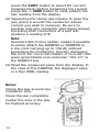
General Tools DAMP68 User manual
- Category
- Cable network testers
- Type
- User manual
This manual is also suitable for

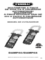
AUTO RANGING
600A AC
CLAMP METER/
AUTO RANGING
AC/DC TRUE
RMS 400A
CLAMP METER
USER’S MANUAL
DAMP60/DAMP68
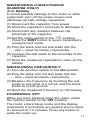
Please read this manual carefully and thoroughly before using this product.

TABLE OF CONTENTS
Introduction . . . . . . . . . . . . . . . . . . . . . . . . . 3
Key Features . . . . . . . . . . . . . . . . . . . . . 4 –5
What's in the Blister Pack . . . . . . . . . . . . . 5
Product Overview . . . . . . . . . . . . . . . . . 5 –7
Safety Instructions . . . . . . . . . . . . . . . 8 – 11
Setup Instructions . . . . . . . . . . . . . . . . . . . 11
Install Batteries . . . . . . . . . . . . . . . . . . . 11
Operating Instructions . . . . . . . . . . . 11 – 17
Measuring AC or DC Current . . . . . 11 – 12
Measuring DC Voltage . . . . . . . . . . . . . . 13
Measuring AC Voltage . . . . . . . . . . . . . . 14
Measuring Resistance . . . . . . . . . . 14 – 15
Checking the Integrity of a Diode
. . 15 – 16
Checking for Continuity . . . . . . . . . . . . . 16
Measuring Temperature
(DAMP68 only) . . . . . . . . . . . . . . . . . . . . 16
Measuring Capacitance
(DAMP68 only) . . . . . . . . . . . . . . . . . . . . 17
Measuring Frequency . . . . . . . . . . . . . . 17
Powering Off . . . . . . . . . . . . . . . . . . . . . . 17
Specifications . . . . . . . . . . . . . . . . . . 18 – 21
Warranty Information . . . . . . . . . . . . . . . . 22
Return for Repair Policy . . . . . . . . . . . . . . 23
Manuel de L’Utilisateur . . . . . . . . . . . 25 – 47
2

INTRODUCTION
Thank you for purchasing General Tools &
Instruments’ (General’s) DAMP60 or DAMP68
Auto Ranging Clamp Meter. Please read this
user’s manual carefully and thoroughly before
using the instrument.
Each meter combines the functions of a voltmeter
and a clamp-type ammeter. Both are designed for
use in an industrial setting.
The DAMP60 is designed to be used by HVAC/R
contractors, building maintenance technicians
and electricians.
The DAMP68—with more features (see table
below)—is designed for precise measurement
and analysis of AC/DC power circuits by
process/power plant operators, HVAC/R
contractors and electrical technicians.
The DAMP60 and DAMP68 are easy to use,
ruggedly built and designed for safety. Both
instruments are ETL certified for CAT III 600V use.
3
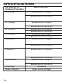
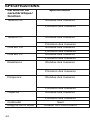
KEY FEATURES & SPECS COMPARISON
Feature or Specification DAMP68 DAMP60
Parameters Measured AC/DC voltage, AC/DC voltage, AC current,
AC/DC current, resistance, resistance, frequency
frequency, capacitance,
temperature
AC Current Range 0 to 400A 0 to 600A
DC Current Range 0 to 400A N/A
True RMS Voltage & Yes No
Current Readings
Resistance Range 0 to 40MΩ 0 to 20MΩ
Frequency Range 0 to 9.999MHz 10 to 1999Hz
Capacitance Range 0 to 4000F N/A
Temperature Range -40° to 752°F N/A
(-40° to 400°C)
Clamp Jaw Type Coil-type + Hall effect Coil-type
Opening 1.48 in. (37.5mm) 1.48 in. (37.5mm)
Display Maximum Count 4000 2000
Analog Bar Graph Yes No
Ranging Options Auto or manual Autoranging only
Zero Offset Yes No
Memory No Maximum value
Power Source Three “AAA” batteries Two “AAA” batteries

KEY FEATURES
DAMP60 AUTO RANGING 600A AC
CLAMP METER
• 7 functions, 20 ranges
• CAT III 600V ETL certified
• Measures AC and DC voltage, AC current,
resistance and frequency
• Handles up to 600A AC
• Verifies integrity of diodes and checks circuits
for continuity
• Jumbo 3-1/2 digit (2000 count) backlit LCD
• Ergonomic design with rugged rubber housing
• Max memory, data hold buttons
• Auto power off
• Coil-type clamp jaw
with 1.48 in. (37.5mm) opening
DAMP68 AUTO RANGING AC/DC
TRUE RMS 400A CLAMP METER
• 11 functions, 34 ranges
• CAT III 600V ETL certified
• Computes and displays True RMS values
• Measures AC/DC voltage, AC/DC current,
resistance, capacitance and frequency
• Handles up to 400A AC or DC
• Also measures temperature with included “K”
type thermocouple
• Verifies integrity of diodes and checks circuits
for continuity
• Jumbo 3-3/4 digit (4000 count) backlit LCD
+ analog bar graph
4

• Auto ranging or manual ranging
• Ergonomic design with rugged rubber housing
• Data hold, zero offset buttons
• Coil-type + Hall effect clamp jaw
with 1.48 in. (37.5mm) opening
WHAT’S IN THE
BLISTER PACK
The DAMP60 and DAMP68 each come in a blister
pack along with a black soft pouch with a belt
loop.
The pouch for the DAMP60 contains a pair of red
and black test leads, (2) “AAA” batteries and this
user’s manual.
The pouch for the DAMP68 contains a pair of red
and black test leads, a “K” type thermocouple
probe, (3) “AAA” batteries and this user’s
manual.
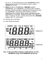
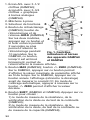
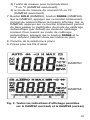
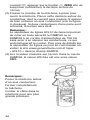
PRODUCT OVERVIEW
Fig. 1 shows the labels and positions of the
controls and connectors on the front of the
DAMP60 and DAMP68. Fig. 2 shows all possible
display indications on both units. Familiarize
yourself with the functions and meanings of these
controls, indicators and connectors before
moving on to the Setup Instructions.
5

6
1. 3-1/2 digit LCD
(DAMP60); 3-3/4 digit
LCD + analog bar
graph (DAMP68)
2. Clamp jaw
3. Function switch
4. Backlight button
(DAMP60);
Backlight/
HOLD
button
(DAMP68). On both
models, pressing and
holding this button for
2+ seconds turns
display backlight on
for 10 seconds. On
DAMP68, pressing
this button briefly
holds/releases
displayed
measurement.
5.
MAX
button (DAMP60);
ZERO
button
(DAMP68). On DAMP60, pressing this button
displays maximum value of displayed
parameter over time. On DAMP68, pressing
this button “zeroes out” the display (subtracts
the offset) before measuring DC current. In
auto ranging mode, pressing the
ZERO
button again displays the offset value.
6.
SHIFT
button (DAMP60 and DAMP68).
Press to select:
1) resistance measurement, diode check or
continuity check mode (DAMP60);
2) resistance measurement, diode check,
continuity check or capacitance measurement
mode (DAMP68);
3
2
5
7
9
4
1
6
8
Fig. 1. The controls,
indicators and
connectors of the
DAMP60 and DAMP68

3) °F or °C temperature unit (DAMP68 only);
4) AC or DC current measurement mode
(DAMP68 only)
7.
HOLD
button (DAMP60);
RANGE
button
(DAMP68). On DAMP60, pressing this button
briefly holds/releases displayed measurement.
On DAMP68, pressing this button briefly
switches the meter from auto ranging mode
(default) to manual ranging mode. To return to
auto ranging mode, press and hold the
RANGE
button for 2+ seconds.
8. Clamp jaw release
9. Test lead sockets
DAMP60
DAMP68
7
Fig. 2. All possible display indications on the
DAMP60 (top) and DAMP68 (bottom)

8
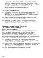
SAFETY INSTRUCTIONS
WARNING
To avoid possible electric shock or personal
injury, and to avoid damaging the meter or the
equipment under test:
• Do not use the meter in any way not detailed in
this manual or the meter's safety features may
be compromised.
• Before using the meter, inspect the case.
Do not use the meter if it is damaged. Look for
cracks or missing plastic. Pay particular
attention to the insulation around the
connectors.
•
WARNING
Inspect the test leads for damaged
insulation or exposed metal. Check the test
leads for continuity. Replace damaged test
leads before using the meter.
• Verify the meter’s operation by measuring a
known voltage. Do not use the meter if it
operates abnormally. Protection may be
impaired. When in doubt, have the meter
serviced.
•
WARNING
Do not apply more than the rated
voltage, as marked on the meter, between the
terminals or between any terminal and ground.
•
WARNING
Do not measure voltages above
600V in Category III installations.
•
WARNING
Do not measure voltage when the
function switch points to the resistance (ohms),
current, capacitance or temperature settings.
Never measure current when the switch points
to the resistance (ohms), capacitance or
temperature settings.

• Use caution when working with voltages above
42V ACrms, or 60V DC. These voltages pose a
shock hazard.
• Use the proper terminals, function, and range
for all measurements.
•
WARNING
Do not operate the meter around
explosive gas, vapor, or dust.
•
WARNING
When using the probes, keep your
fingers behind the finger guards. Do not touch
the metal probes of the test leads when making
a measurement.
• When making connections, connect the
black (–) test lead before connecting the
red (+) test lead; when disconnecting,
disconnect the red (+) test lead before
disconnecting the black (–) test lead.
• Disconnect circuit power and discharge all
high-voltage capacitors before
measuring/testing resistance, continuity,
diodes, or capacitance.
• For all DC functions in both auto and manual
ranging mode, to avoid the risk of shock due to
possible improper reading verify the presence
of any AC voltages by first using the AC
function. Then select a DC voltage range equal
to or greater than the AC range.
• Before measuring current, turn off power to
the circuit before connecting the meter.
• Do not operate the meter with the case
(or part of the case) removed.
9

• Use only two “AAA” batteries (DAMP60), or
three “AAA” batteries (DAMP68), properly
installed in the battery compartment, to power
the meter. Do not use rechargeable batteries.
• Replace the batteries as soon as the low
battery indicator “ ” appears. Operated with
weak batteries, the meter might produce false
readings that could lead to electric shock and
personal injury.
• Remove the test leads from the meter before
opening the meter case or battery
compartment.
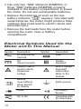
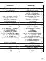
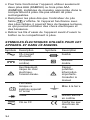
Electrical Symbols Used On the
Meter and In This Manual
Symbol Description Symbol Description
AC (Alternating Fuse
Current)
DC Double
(Direct Current) Insulated
Caution, risk of Risk of danger.
electric shock. Important
Hazardous information.
voltage. Refer to the
manual.
Battery
(Low battery) Earth ground
when shown
on display
Diode Continuity
Beeper
AC or DC Complies with
EU directives
10

Symbol Description Symbol Description
Application and For measurements
removal from made on building
hazardous live equipment such
conductors as distribution
permitted panels, feeders
and short branch
circuits, and on
lighting systems in
large buildings.
SETUP INSTRUCTIONS
INSTALL BATTERIES
The battery compartment of the DAMP60 and
DAMP68 is located at the back of the meter.
To open the compartment, use a small Phillips-
head screwdriver to remove the single screw
securing the battery compartment cover. Be
careful not to lose the small screw. Put the screw
and the cover to the side.
Install the supplied “AA” batteries (two in the
case of the DAMP60; three for the DAMP68) in
the battery compartment. Use the polarity marks
stenciled inside the compartment as a guide.
Replace the battery compartment cover and
secure it with the Phillips-head screw.
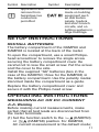
OPERATING INSTRUCTIONS
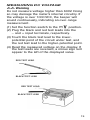
MEASURING AC OR DC CURRENT
Warning
Before making current measurements, make
certain that all test leads are disconnected from
the meter terminals.
(1) Set the function switch to the (DAMP60)
or (DAMP68) position. For DAMP68,
AC current measurement is the default mode;
11

press the
SHIFT
button to select DC current
measurement. Before measuring DC current,
press the
ZERO
button to clear (offset) the
last reading from the display.
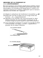
(2) Squeezing the clamp jaw release to open the
jaw, place it around the conductor whose
current you wish to measure. Be sure to
enclose only one conductor (see figure below).
Enclosing both conductors of a pair will
produce a reading of
0
.
Note:
General’s ACL10 line splitter makes it possible
to safely attach the DAMP60 or DAMP68 to
a line cord carrying up to 15A AC without
separating its conductors, thereby damaging
the cord. For more information or to order, visit
www.generaltools.com and enter “ACL10” in
the SEARCH box.
(3) Read the measured value from the display. In
the case of the DAMP68, the displayed value
is a True RMS reading.
Notes:
Clamp the jaw around one
conductor only.
Close the jaw completely.
Center the wire in the jaw
for highest accuracy.
12

MEASURING DC VOLTAGE
Warning
Do not measure voltage higher than 600V. Doing
so may damage the meter’s internal circuitry. If
the voltage is over 1000 VDC, the beeper will
sound continuously, indicating an over-range
measurement.
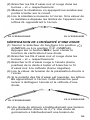
(1) Set the function switch to the position.
(2) Plug the black and red test leads into the
– and + input terminals, respectively.
(3) Touch the black test lead to the lower-
potential point of the circuit under test, and
the red test lead to the higher-potential point.
(4) Read the measured voltage on the display. If
the test leads are reversed, a minus sign will
appear to the left of the displayed value.
13
RED TEST LEAD
BLACK TEST LEAD
RED TEST LEAD
BLACK TEST LEAD

MEASURING AC VOLTAGE
Warning
Do not measure voltages higher than 600V AC or
internal damage will occur. If the applied voltage
is over 750V AC, the beeper will sound
continuously, indicating an over-range
measurement.
(1) Set the function switch to the position.
(2) Plug the black and red test leads into the
– and + input terminals, respectively.
(3) Measure the voltage by touching the probes to
the desired points of the circuit. With AC
voltage, the polarity of the test leads is not a
factor.
(4) Read the measured voltage on the display.
MEASURING RESISTANCE
Warning
To avoid electrical shock or damage to the meter
when measuring resistance or continuity in a
circuit, make sure the power to the circuit is
turned off and all capacitors are discharged.
(1) Turn the function switch to the (DAMP60)
or (DAMP68) position. Make sure power is
disconnected from the circuit to be measured.
Resistance measurement is the default
function for this function switch position on
both the DAMP60 and DAMP68.
14
RED TEST LEAD
BLACK TEST LEAD

(2) Plug the black and red test leads into the
– and + input terminals, respectively.
(3) Measure the resistance by touching the
probes to the desired test points of the circuit.
(4) Read the measured resistance on the display.
If the resistance value is over range,
OL
will
appear on the display.
CHECKING THE INTEGRITY
OF A DIODE
(1) Turn the function switch to the (DAMP60)
or (DAMP68) position. Press the
SHIFT
button to select the diode check function.
(2) Plug the black and red test leads into the
– and + input terminals, respectively.
(3) Connect the red test lead to the anode
(positive terminal) of the diode to be tested,
and the black test lead to its cathode
(negative terminal).
(4) Read the forward bias voltage value on the
display.
(5) If the polarity of the test leads is reversed,
OL
will appear on the display. This can be used to
distinguish the anode and cathode of a diode.
(6) A silicon diode typically has a forward bias
voltage of 0.7V. A germanium diode typically
has a forward bias voltage of 0.3V. A
0V
reading in both directions indicates a shorted
15
RED TEST LEAD
BLACK TEST LEAD
RED TEST LEAD
BLACK TEST LEAD

diode. An
OL
reading indicates an open diode.
In either case, the diode is defective and
should be replaced.
CHECKING FOR CONTINUITY
(1) Turn the function switch to the (DAMP60)
or (DAMP68) position. Press the
SHIFT
button to select continuity checking mode.
(2) Plug the black and red test leads into the
– and + input terminals, respectively.
(3) Touch the test leads to any two points of a
circuit. If the resistance between those points
is ⭐30⍀, the beeper will sound continuously.
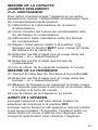
MEASURING TEMPERATURE
(DAMP68 ONLY)
Warning
To avoid possible damage to the meter or
other equipment, remember that the included
“K” Type thermocouple is rated -40° to 752°F
(-40° to 400°C).
When the meter is not connected to the included
thermocouple,
OL
will be shown on the display.
(1) Turn the function switch to the
°C/°F
position.
°C
is the default setting. Press the SHIFT
button to select
°F
.
(2) Plug the included “K” type thermocouple into
the meter's – and + terminals, making sure to
insert the pin marked + into the + terminal.
(3) Read the measured temperature on the
display.
16

MEASURING CAPACITANCE
(DAMP68 ONLY)
Warning
To avoid possible damage to the meter or other
equipment, turn off the power source and
discharge all high-voltage capacitors.
(1) Disconnect the capacitor from power.
(2) Short the capacitor’s terminals to discharge it.
(3) Disconnect any resistors between the
terminals of the capacitor.
(4) Set the rotary switch to the position.
Press the
SHIFT
button to select capacitance
measurement mode.
(5) Plug the black and red test leads into the
– and + input terminals, respectively.
(6) Connect the test leads to the terminals of the
capacitor.
(7) Read the measured capacitance value on the
display.
MEASURING FREQUENCY
(1) Turn the function switch to the
Hz
position.
(2) Plug the black and red test leads into the
– and + input terminals, respectively.
(3) Measure the frequency by touching the red
probe to any point of a circuit, and the black
probe to circuit ground.
(4) Read the measured frequency on the display.
POWERING OFF
When you have finished using the meter, rotate
the function switch to the
OFF
position.
The meter enters Sleep mode and the display
goes blank if no buttons are pushed and no input
is received for 15 minutes. Press any button to
wake the meter up.
17

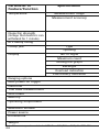
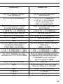
SPECIFICATIONS
Parameter or Specification
Feature/Function
AC voltage Measurement ranges
Measurement accuracy
DC voltage Measurement ranges
Measurement accuracy
AC current Measurement range(s)
Measurement accuracy
DC current Measurement range
Measurement accuracy
Resistance Measurement ranges
Measurement accuracy
Frequency Measurement range(s)
Measurement accuracy
Capacitance Measurement ranges
Measurement accuracy
Continuity Threshold
Diode integrity Open circuit voltage
18
Page is loading ...

20
Parameter or Specification
Feature/Function
Temperature Measurement range
Measurement accuracy
Dielectric strength
(Voltage that dielectric can
withstand for 1 minute)
ETL safety rating
Clamp jaw Type
Opening
Display No. of digits
Maximum count
Analog bar graph
Backlight
Overload indication
Low battery indication
Ranging options
Auto power off trigger
Data hold
True RMS measurement
Zero offset
Memory
Operating temperature
Maximum altitude
Power source
Dimensions
Weight
Note: All accuracy values stated at 73° F ± 4°F (23° ± 3°C) @<75% RH

21
DAMP60 DAMP68
N/A -40° to 752°F (-40° to 400°C)
N/A
±(8% + 8 digits) from -40° to 4°F;
±(1.2% + 7 digits) from
4° to 32°F ; ±(1.2% + 6 digits)
from 32° to 212°F;
±(3% + 5 digits)@≥212°F
6000V AC 6000V AC
CAT III 600V
Coil-type Coil-type + Hall effect
1.48 in. (37.5mm) 1.48 in. (37.5mm)
3-1/2 3-3/4
2000 4000
No Yes
Yes Yes
Yes Yes
Yes Yes
Auto Auto or manual
15 minutes 15 minutes
Yes Yes
No Yes
No Yes
Maximum value No
32° to 104°F (0° to 40°C) 32° to 104°F (0° to 40°C)
@<75% relative humidity @<75% relative humidity
6562 ft. (2000m) 6562 ft. (2000m)
Two “AAA” batteries Three “AAA” batteries
11.25 x 6.13 x 2.75 in. 11.38 x 6.25 x 2.75 in.
(286 x 156 x 70mm) (289 x 159 x 70mm)
17 oz. (482g) 19 oz. (539g)
Page is loading ...
Page is loading ...
Page is loading ...
Page is loading ...
Page is loading ...
Page is loading ...
Page is loading ...
Page is loading ...
Page is loading ...
Page is loading ...
Page is loading ...
Page is loading ...
Page is loading ...
Page is loading ...
Page is loading ...
Page is loading ...
Page is loading ...
Page is loading ...
Page is loading ...
Page is loading ...
Page is loading ...
Page is loading ...
Page is loading ...
Page is loading ...
Page is loading ...
Page is loading ...
Page is loading ...
-
 1
1
-
 2
2
-
 3
3
-
 4
4
-
 5
5
-
 6
6
-
 7
7
-
 8
8
-
 9
9
-
 10
10
-
 11
11
-
 12
12
-
 13
13
-
 14
14
-
 15
15
-
 16
16
-
 17
17
-
 18
18
-
 19
19
-
 20
20
-
 21
21
-
 22
22
-
 23
23
-
 24
24
-
 25
25
-
 26
26
-
 27
27
-
 28
28
-
 29
29
-
 30
30
-
 31
31
-
 32
32
-
 33
33
-
 34
34
-
 35
35
-
 36
36
-
 37
37
-
 38
38
-
 39
39
-
 40
40
-
 41
41
-
 42
42
-
 43
43
-
 44
44
-
 45
45
-
 46
46
-
 47
47
-
 48
48


General Tools DAMP68 User manual
- Category
- Cable network testers
- Type
- User manual
- This manual is also suitable for
Ask a question and I''ll find the answer in the document
Finding information in a document is now easier with AI
in other languages
- français: General Tools DAMP68 Manuel utilisateur
Related papers
Other documents
-
UNI-T UT205 User manual
-
Mastech MS8910 User manual
-
GB GDT-3200 Operating instructions
-
-
 Sperry instruments DSA540A Owner's manual
-
ELECTROBES 220+ AC Current Mini Digital Clamp Tester User manual
-
UNI-T UT203 Operating instructions
-
 MULTI MEASURING INSTRUMENTS 104+ AC Current Mini Digital Clamp-On Tester User manual
-
Klein Tools CL330 Operating instructions
-

