
INSTRUCTION MANUAL
GUIDE D'UTILISATION
MANUAL DE INSTRUCCIONES
INSTRUCTIVO DE OPERACIÓN, CENTROS DE SERVICIO Y PÓLIZA DE
GARANTÍA. ADVERTENCIA: LÉASE ESTE INSTRUCTIVO ANTES DE
USAR EL PRODUCTO.
DEWALT Industrial Tool Co., 701 Joppa Road, Towson, MD 21286
(DEC14) Part No. N401624 Copyright © 2014 D
EWALT
D25133, D25260, D25262, D25263
The following are trademarks for one or more DEWALT power tools: the yellow and black color scheme, the “D”
shaped air intake grill, the array of pyramids on the handgrip, the kit box confi guration, and the array of lozenge-
shaped humps on the surface of the tool.
If you have questions or comments, contact us.
Pour toute question ou tout commentaire, nous contacter.
Si tiene dudas o comentarios, contáctenos.
1-800-4-DEWALT • www.dewalt.com
Defi nitions: Safety Guidelines
The defi nitions below describe the level of severity for each signal word. Please read the
manual and pay attention to these symbols.
DANGER: Indicates an imminently hazardous situation which, if not avoided, will result
in death or serious injury.
WARNING: Indicates a potentially hazardous situation which, if not avoided, could result
in death or serious injury.
CAUTION: Indicates a potentially hazardous situation which, if not avoided, may result in
minor or moderate injury.
NOTICE: Indicates a practice not related to personal injury which, if not avoided, may
result in property damage.
IF YOU HAVE ANY QUESTIONS OR COMMENTS ABOUT THIS OR ANY DEWALT TOOL, CALL US
TOLL FREE AT: 1-800-4-D
EWALT (1-800-433-9258).
WARNING: To reduce the risk of injury, read the instruction manual.
General Power Tool Safety Warnings
WARNING! Read all safety warnings and all instructions. Failure to follow the warnings
and instructions may result in electric shock, fi re and/or serious injury.
SAVE ALL WARNINGS AND INSTRUCTIONS
FOR FUTURE REFERENCE
The term “power tool” in the warnings refers to your mains-operated (corded) power tool or battery-
operated (cordless) power tool.
1) WORK AREA SAFETY
a) Keep work area clean and well lit. Cluttered or dark areas invite accidents.
b) Do not operate power tools in explosive atmospheres, such as in the presence of
fl ammable liquids, gases or dust. Power tools create sparks which may ignite the dust or
fumes.
c) Keep children and bystanders away while operating a power tool. Distractions can
cause you to lose control.
2) ELECTRICAL SAFETY
a) Power tool plugs must match the outlet. Never modify the plug in any way. Do not
use any adapter plugs with earthed (grounded) power tools. Unmodifi ed plugs and
matching outlets will reduce risk of electric shock.
b) Avoid body contact with earthed or grounded surfaces such as pipes, radiators,
ranges and refrigerators. There is an increased risk of electric shock if your body is earthed
or grounded.
c) Do not expose power tools to rain or wet conditions. Water entering a power tool will
increase the risk of electric shock.
d) Do not abuse the cord. Never use the cord for carrying, pulling or unplugging the
power tool. Keep cord away from heat, oil, sharp edges or moving parts. Damaged or
entangled cords increase the risk of electric shock.
e) When operating a power tool outdoors, use an extension cord suitable for outdoor
use. Use of a cord suitable for outdoor use reduces the risk of electric shock.
f) If operating a power tool in a damp location is unavoidable, use a ground fault circuit
interrupter (GFCI) protected supply. Use of a GFCI reduces the risk of electric shock.
3) PERSONAL SAFETY
a) Stay alert, watch what you are doing and use common sense when operating a
power tool. Do not use a power tool while you are tired or under the infl uence of
drugs, alcohol or medication. A moment of inattention while operating power tools may
result in serious personal injury.
b) Use personal protective equipment. Always wear eye protection. Protective equipment
such as dust mask, non-skid safety shoes, hard hat, or hearing protection used for appropriate
conditions will reduce personal injuries.
c) Prevent unintentional starting. Ensure the switch is in the off position before
connecting to power source and/or battery pack, picking up or carrying the tool.
Carrying power tools with your fi nger on the switch or energizing power tools that have the
switch on invites accidents.
d) Remove any adjusting key or wrench before turning the power tool on. A wrench or
a key left attached to a rotating part of the power tool may result in personal injury.
e) Do not overreach. Keep proper footing and balance at all times. This enables better
control of the power tool in unexpected situations.
f) Dress properly. Do not wear loose clothing or jewelry. Keep your hair, clothing and
gloves away from moving parts. Loose clothes, jewelry or long hair can be caught in
moving parts.
g) If devices are provided for the connection of dust extraction and collection facilities,
ensure these are connected and properly used. Use of dust collection can reduce dust-
related hazards.
4) POWER TOOL USE AND CARE
a) Do not force the power tool. Use the correct power tool for your application. The
correct power tool will do the job better and safer at the rate for which it was designed.
b) Do not use the power tool if the switch does not turn it on and off. Any power tool that
cannot be controlled with the switch is dangerous and must be repaired.
c) Disconnect the plug from the power source and/or the battery pack from the power
tool before making any adjustments, changing accessories, or storing power tools.
Such preventive safety measures reduce the risk of starting the power tool accidentally.
d) Store idle power tools out of the reach of children and do not allow persons
unfamiliar with the power tool or these instructions to operate the power tool. Power
tools are dangerous in the hands of untrained users.
e) Maintain power tools. Check for misalignment or binding of moving parts, breakage
of parts and any other condition that may affect the power tool’s operation. If
damaged, have the power tool repaired before use. Many accidents are caused by
poorly maintained power tools.
f)
Keep cutting tools sharp and clean. Properly maintained cutting tools with sharp cutting
edges are less likely to bind and are easier to control.
g) Use the power tool, accessories and tool bits, etc. in accordance with these
instructions, taking into account the working conditions and the work to be
performed. Use of the power tool for operations different from those intended could result in
a hazardous situation.
5) SERVICE
a) Have your power tool serviced by a qualifi ed repair person using only identical
replacement parts. This will ensure that the safety of the power tool is maintained.
Additional Safety Instructions for Rotary Hammers
• Wear ear protectors. Exposure to noise can cause hearing loss.
• Use auxiliary handle(s) if supplied with the tool. Loss of control can cause personal injury.
• Hold power tools by insulated gripping surfaces when performing an operation where
the cutting accessory may contact hidden wiring or its own cord. Cutting accessory
contacting a “live” wire may make exposed metal parts of the power tool “live” and could give
the operator an electric shock.
• Use clamps or other practical way to secure and support the workpiece to a stable
platform. Holding the work by hand or against your body is unstable and may lead to loss of
control.
• Wear safety goggles or other eye protection. Hammering operations cause chips to fl y. Flying
particles can cause permanent eye damage. Wear a dust mask or respirator for applications that
generate dust. Ear protection may be required for most applications.
• Keep a fi rm grip on the tool at all times. Do not attempt to operate this tool without
holding it with both hands. It is recommended that the side handle be used at all times.
Operating this tool with one hand will result in loss of control. Breaking through or encountering
hard materials such as re-bar may be hazardous as well. Tighten the side handle securely before
use.
• Do not operate this tool for long periods of time. Vibration caused by hammer action may
be harmful to your hands and arms. Use gloves to provide extra cushion and limit exposure by
taking frequent rest periods.
• Do not recondition bits yourself. Chisel reconditioning should be done by an authorized
specialist. Improperly reconditioned chisels could cause injury.
• Wear gloves when operating tool or changing bits. Accessible metal parts on the tool and
bits may get extremely hot during operation. Small bits of broken material may damage bare
hands.
• Never lay the tool down until the bit has come to a complete stop. Moving bits could
cause injury.
• Do not strike jammed bits with a hammer to dislodge them. Fragments of metal or material
chips could dislodge and cause injury.
• Slightly worn chisels can be resharpened by grinding.
• Keep the power cord away from the rotating bit. Do not wrap the cord around any part
of your body. An electric cord wrapped around a spinning bit may cause personal injury and
loss of control.
• Air vents often cover moving parts and should be avoided. Loose clothes, jewelry or long
hair can be caught in moving parts.
• An extension cord must have adequate wire size (AWG or American Wire Gauge) for
safety. The smaller the gauge number of the wire, the greater the capacity of the cable, that is
16 gauge has more capacity than 18 gauge. An undersized cord will cause a drop in line voltage
resulting in loss of power and overheating. When using more than one extension to make up
the total length, be sure each individual extension contains at least the minimum wire size. The
following table shows the correct size to use depending on cord length and nameplate ampere
rating. If in doubt, use the next heavier gauge. The smaller the gauge number, the heavier the
cord.
Minimum Gauge for Cord Sets
Ampere Rating
Volts Total Length of Cord in Feet (meters)
120V 25 (7.6) 50 (15.2) 100 (30.5) 150 (45.7)
240V 50 (15.2) 100 (30.5) 200 (61.0) 300 (91.4)
More
Than
Not More
Than
AWG
0 6 18 16 16 14
610 18161412
10 12 16 16 14 12
12 16 14 12 Not Recommended
WARNING: ALWAYS use safety glasses. Everyday eyeglasses are NOT safety glasses. Also use
face or dust mask if cutting operation is dusty. ALWAYS WEAR CERTIFIED SAFETY EQUIPMENT:
• ANSI Z87.1 eye protection (CAN/CSA Z94.3),
• ANSI S12.6 (S3.19) hearing protection,
• NIOSH/OSHA/MSHA respiratory protection.
WARNING: Some dust created by power sanding, sawing, grinding, drilling, and other
construction activities contains chemicals known to the State of California to cause cancer, birth
defects or other reproductive harm. Some examples of these chemicals are:
• lead from lead-based paints,
• crystalline silica from bricks and cement and other masonry products, and
• arsenic and chromium from chemically-treated lumber.
Your risk from these exposures varies, depending on how often you do this type of work. To reduce
your exposure to these chemicals: work in a well ventilated area, and work with approved safety
equipment, such as those dust masks that are specially designed to fi lter out microscopic particles.
• Avoid prolonged contact with dust from power sanding, sawing, grinding, drilling, and
other construction activities. Wear protective clothing and wash exposed areas with
soap and water. Allowing dust to get into your mouth, eyes, or lay on the skin may promote
absorption of harmful chemicals.
WARNING: Use of this tool can generate and/or disperse dust, which may cause serious and
permanent respiratory or other injury. Always use NIOSH/OSHA approved respiratory protection
appropriate for the dust exposure. Direct particles away from face and body.
WARNING: Always wear proper personal hearing protection that conforms to ANSI
S12.6 (S3.19) during use. Under some conditions and duration of use, noise from this product
may contribute to hearing loss.
• The label on your tool may include the following symbols. The symbols and their defi nitions are
as follows:
V ..................... volts A ........................amperes
Hz ................... hertz W ....................... watts
min .................minutes
or AC ............alternating current
or DC .....direct current or AC/DC .....alternating or direct current
...................Class I Construction
n
o.......................no load speed
.......................
(grounded) n .........................rated speed
...................Class II Construction ....................... earthing terminal
(double insulated)
.......................safety alert symbol
…/min ............per minute BPM ...................beats per minute
IPM .................impacts per minute RPM ...................revolutions per minute
SPM ...............strokes per minute sfpm ...................surface feet per minute
SAVE THESE INSTRUCTIONS FOR FUTURE USE
Motor
Be sure your power supply agrees with the nameplate marking. Voltage decrease of more than
10% will cause loss of power and overheating. DEWALT tools are factory tested; if this tool does not
operate, check power supply.
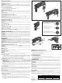
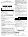
COMPONENTS (Fig. 1)
WARNING: Never modify the power tool or any part of it. Damage or personal injury could result.
A. Variable speed switch F. Chuck
B. Main handle G. Depth adjustment rod
C. Forward/Reverse lever H. Side handle
D. Mode selector I. Depth rod button
E. Mode selector button J. Locking collar
INTENDED USE
These heavy-duty rotary hammers have been designed for professional drilling and hammerdrilling,
screwdriving and light chipping at various work sites (i.e., construction sites). DO NOT use under
wet conditions or in presence of fl ammable liquids or gases.
These heavy-duty rotary hammers are professional power tools. DO NOT let children come into
contact with the tool. Supervision is required when inexperienced operators use this tool.
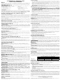
Active Vibration Control (Fig. 1)
D25262, D25263 ONLY
The active vibration control (K) reduces rebound vibration from the hammer mechanism. Reducing
hand and arm vibration allows for more comfortable use for longer periods of time and extends the
life of the unit.
For best vibration control, hold the tool with one hand on the main handle (B) and the other hand on
the side handle (H). Apply just enough pressure so the hammer is approximately mid-stroke.
The hammer only needs enough pressure to engage the active vibration control. Applying too much
pressure will not make the tool drill or chip faster and active vibration control will not engage.
D25133, D25262 Heavy-Duty 1" (26 mm) SDS Plus Rotary Hammers, Marteaux rotatifs industriels SDS Plus, 26mm (1po),
Rotomartillos SDS Plus de 26mm (1") para trabajos pesados
D25260 Heavy-Duty 7/8" (24 mm) SDS Plus Rotary Hammers, Marteaux rotatifs industriels SDS Plus, 24mm (7/8po),
Rotomartillos SDS Plus de 24mm (7/8") para trabajos pesados
D25263 Heavy-Duty 1-1/8" (28 mm) SDS Plus Rotary Hammer, Marteaux rotatifs industriels SDS Plus, 28 mm (1-1/8 po),
Rotomartillos SDS Plus de 28 mm (1-1/8") para trabajos pesados

Mechanical Clutch
All rotary hammer drills are equipped with a torque limiting clutch that reduces the maximum torque
reaction transmitted to the operator in case of jamming of a drill bit. This feature also prevents the
gearing and electric motor from stalling. The torque limiting clutch has been factory-set and cannot
be adjusted.
Side Handle (Fig. 2)
WARNING: To reduce the risk of personal injury, ALWAYS operate the tool with the side handle
properly installed and securely tightened. Failure to do so may result in the side handle slipping
during tool operation and subsequent loss of control. Hold tool with both hands to maximize control.
A side handle comes assembled with this rotary hammer. The side handle (H) can be fitted to suit
both right-hand and left-hand users.
TO ADJUST THE SIDE HANDLE
1. Loosen the side handle (H) by turning it counterclockwise.
2. Rotate the side handle to the desired position.
3. Tighten the side handle by turning it clockwise.
Trigger Switch (Fig. 1)
To start the rotary hammer, depress the variable speed trigger switch (A). To stop rotary hammer,
release the switch.
NOTE: Use lower speeds for starting holes without a centerpunch, drilling in metal, plastics or
ceramics, or driving screws. Higher speeds are better for drilling in masonry for maximum effi ciency.
VARIABLE SPEED
The variable speed trigger switch (A) permits speed control. The farther the trigger switch is
depressed, the higher the speed of the drill.
Forward/Reverse Lever (Fig. 1)
The forward/reverse lever (C) is used to reverse the rotary hammer for backing out fasteners or
jammed bits in drill-only mode.
CAUTION: When reversing to clear jammed bits, be ready for strong reactive torque.
To reverse the rotary hammer, turn it off and align the forward/reverse lever (C) with the yellow arrow
pointing backward (viewed when holding drill in operating position).
To position the lever for forward operation, turn the rotary hammer off and align the forward/reverse
lever (C) with the yellow arrow pointing forward (viewed when holding drill in operating position).
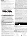
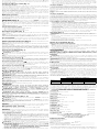
Mode Selector (Fig. 3)
D25133, D25260, D25262, D25263
WARNING: Do not operate in drill or hammerdrill mode with a chisel bit in the chuck. Personal
injury and damage to tool may result.
NOTICE: Tool must come to a complete stop before activating the mode selector button or damage
to the tool may result.
DRILL-ONLY MODE
To use drill-only mode, press mode selector button (E) and turn the mode selector (D) so the yellow
arrow points to the corresponding symbol as shown. Use drill-only mode for wood, metal, and
plastics.
HAMMERDRILL MODE
To use hammerdrill mode, press the mode selector button (E) and turn the mode selector (D) so the
yellow arrow points to the corresponding symbol as shown. Use this mode for masonry drilling.
HAMMER-ONLY MODE
For light chiseling, press the mode selector button (E) and turn the mode selector (D) so the yellow
arrow points to the corresponding symbol as shown.
NOTE: The yellow arrow on the mode selector MUST be aligned with the one of the symbols at all
times. There are no operable positions between the positions.
SDS Plus Chuck (Fig. 1)
WARNING: To reduce the risk of serious personal injury, turn tool off and disconnect tool
from power source before making any adjustments or removing/installing attachments or
accessories.
WARNING: Burn Hazard. ALWAYS wear gloves when changing bits. Accessible metal parts on
the tool and bits may get extremely hot during operation. Small bits of broken material may damage
bare hands.
WARNING: Do not attempt to tighten or loosen drill bits (or any other accessory) by gripping the
front part of the chuck and turning the tool on. Damage to the chuck and personal injury may occur.
To insert bit, insert shank of bit about 3/4" (19 mm), no further than 7/8" (24 mm) into chuck (F).
Push and rotate bit until it locks in place. The bit will be securely held.
To release bit, pull the chuck sleeve (F) back and remove the bit.
OPERATION
WARNING: To reduce the risk of injury, turn unit off and disconnect it from power source
before installing and removing accessories, before adjusting or when making repairs. An
accidental start-up can cause injury.
WARNING: To reduce the risk of personal injury, ALWAYS ensure workpiece is anchored
or clamped fi rmly. If drilling thin material, use a wood “back-up” block to prevent damage to the
material.
WARNING: To reduce the risk of personal injury, ALWAYS operate the tool with the side
handle properly installed and securely tightened. Failure to do so may result in the side handle
slipping during tool operation and subsequent loss of control. Hold tool with both hands to maximize
control.
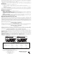
Proper Hand Position (Fig. 1, 4)
WARNING: To reduce the risk of serious personal injury, ALWAYS use proper hand position as
shown.
WARNING: To reduce the risk of serious personal injury, ALWAYS hold securely in anticipation
of a sudden reaction.
Proper hand position requires one hand on the side handle (H), with the other hand on the main
handle (B).
Drilling Tools
The machine is intended for hammerdrilling in concrete, brick and stone. It is also suitable for drilling
without impact in wood, metal, ceramic and plastic.
Chipping Tools
The machine is intended for chipping in concrete, brick and stone.
Drilling
Press mode selector button (E) and turn the mode selector (D) to the drill bit symbol for drilling, to the
hammer symbol for hammering or to the hammerdrill symbol for hammerdrilling.
DRILLING OPERATION
1. For WOOD, use twist bits, spade bits, power auger bits or hole saws. For METAL, use high-speed
steel twist drill bits or hole saws. Use a cutting lubricant when drilling metals. The exceptions
are cast iron and brass which should be drilled dry. For MASONRY, use carbide-tipped bits or
masonry bits. A smooth, even fl ow of dust indicates the proper drilling rate.
2. Always apply pressure in a straight line with the bit. Use enough pressure to keep the drill bit
biting, but do not push hard enough to stall the motor or defl ect the bit.
3. Hold tool fi rmly with both hands to control the twisting action of the drill.
WARNING: Drill may stall if overloaded causing a sudden twist. Always expect the stall. Grip
the drill fi rmly with both hands to control the twisting action and avoid injury.
4. IF DRILL STALLS, it is usually because it is being overloaded. RELEASE TRIGGER
IMMEDIATELY, remove drill bit from work, and determine cause of stalling. DO NOT CLICK
TRIGGER OFF AND ON IN AN ATTEMPT TO START A STALLED DRILL – THIS CAN
DAMAGE THE DRILL.
5. To minimize stalling or breaking through the material, reduce pressure on drill and ease the bit
through the last fractional part of the hole.
6. Keep the motor running when pulling the bit back out of a drilled hole. This will help prevent
jamming.
7. With variable speed drills there is no need to center punch the point to be drilled. Use a slow
speed to start the hole and accelerate by squeezing the trigger harder when the hole is deep
enough to drill without the bit skipping out.
DRILLING IN METAL
An SDS Plus round shank adaptor chuck is required for metal drilling. Ensure that tool is in drill-only
mode. Start drilling with slow speed and increase to full power while applying fi rm pressure on the
tool. A smooth even fl ow of metal chips indicates the proper drilling rate. Use a cutting lubricant
when drilling metals. The exceptions are cast iron and brass which should be drilled dry.
NOTE: Large (5/16" to 1/2" [7.9 mm to 12.7 mm]) holes in steel can be made easier if a pilot hole
(5/32" to 3/16" [4 mm to 4.8 mm]) is drilled fi rst.
DRILLING IN WOOD
An SDS Plus round shank adaptor chuck is required for drilling in wood. Ensure that tool is in drill-only
mode. Start drilling with slow speed and increase to full power while applying fi rm pressure on the
tool. Holes in wood can be made with the same twist drills used for metal. These bits may overheat
unless pulled out frequently to clear chips from the fl utes. For larger holes, use spade bits, power
auger bits, or hole saws. Work that is apt to splinter should be backed up with a block of wood.
HAMMERDRILL OPERATION
1. When drilling, use just enough force on the hammer to keep it from bouncing excessively or
“rising” off the bit. Too much force will cause slower drilling speeds, overheating, and a lower
drilling rate.
2. Drill straight, keeping the bit at a right angle to the work. Do not exert side pressure on the bit
when drilling as this will cause clogging of the bit fl utes and a slower drilling speed.
3. When drilling deep holes, if the hammer speed starts to drop off, pull the bit partially out of the
hole with the tool still running to help clear debris from the hole.
4. For masonry, use carbide-tipped bits or masonry bits. A smooth even fl ow of dust indicates the
proper drilling rate.
FIG. 5
I
G
H
FIG. 1
H
FIG. 2
Chipping and Chiseling (Fig. 1)
WARNING: Do not operate in drill or hammerdrill mode with a chisel bit in the chuck. Personal
injury and damage to tool may result.
1. Insert chisel while in hammerdrill mode and rotate to desired position.
2. Set the mode selector (D) to the hammer-only position.
3. Adjust the side handle (H) as required.
4. Switch on the tool and start working.
5. Always switch off the tool when work is finished and before unplugging.
Depth Rod (Fig. 5)
TO ADJUST THE DEPTH ROD
1. Push in and hold the depth rod release button (I) on the side handle.
2. Move the depth rod (G) so the distance between the end of the rod and the end of the bit equals
the desired drilling depth.
3. Release the button to lock rod into position. When drilling with the depth rod, stop when end of
rod reaches surface of material.
MAINTENANCE
WARNING: To reduce the risk of injury, turn unit off and disconnect it from power source
before installing and removing accessories, before adjusting or when making repairs. An
accidental start-up can cause injury.
Cleaning
WARNING: Blow dirt and dust out of all air vents with clean, dry air at least once a week. To
minimize the risk of eye injury, always wear ANSI Z87.1 approved eye protection when performing
this.
WARNING: Never use solvents or other harsh chemicals for cleaning the non-metallic parts of the
tool. These chemicals may weaken the plastic materials used in these parts. Use a cloth dampened
only with water and mild soap. Never let any liquid get inside the tool; never immerse any part of the
tool into a liquid.
Lubrication
Your tool was properly lubricated before leaving the factory. In from two to six months, depending
upon use, take or send your tool to an authorized service center for a complete cleaning, inspection
and lubrication. Tools used constantly on production jobs will need relubrication more often. Also,
tools “out of service” for long periods should be relubricated before being put back to work.
Accessories
WARNING: Since accessories, other than those offered by DEWALT, have not been tested with
this product, use of such accessories with this tool could be hazardous. To reduce the risk of injury,
only D
EWALT recommended accessories should be used with this product.
Recommended accessories for use with your tool are available at extra cost from your local dealer or
authorized service center. If you need assistance in locating any accessory, please contact D
EWALT
Industrial Tool Co., 701 East Joppa Road, Towson, MD 21286, call 1-800-4-D
EWALT (1-800-433-
9258) or visit our website: www.dewalt.com.
MAXIMUM RECOMMENDED CAPACITIES
D25260 D25133, D25262 D25263
Masonry 7/8" (24 mm) 1" (26 mm) 1-1/8" (28 mm)
Masonry
Optimum Capacity
3/16"–1/2"
(5 mm–13 mm)
1/4"–5/8"
(6 mm–16 mm)
1/4"–3/4"
(6 mm–19 mm)
Repairs
To assure product SAFETY and RELIABILITY, repairs, maintenance and adjustment (including brush
inspection and replacement) should be performed by a DEWALT factory service center, a DEWALT
authorized service center or other qualifi ed service personnel. Always use identical replacement
parts.
G
F
D25133
FIG. 3
DRILL-ONLY MODE
MODE PERÇAGE SEULEMENT
MODO SÓLO TALADRO
HAMMERDRILL MODE
MODE PERFORATION-PERÇAGE
MODO TALADRO/PERCUTOR
CHISEL ROTATION
ROTATION DU BURIN
ROTACIÓN DE CINCELES
HAMMER-ONLY MODE
MODE PERFORATION SEULEMENT
MODO SÓLO MARTILLO
(D25133, D25260, D25262, D25263)
I
B
D
E
C
H
J
C
B
D
E
I
H
F
J
G
D25263
E
D
A
A
FIG. 4
K
Page is loading ...
Page is loading ...
Page is loading ...
Page is loading ...
Page is loading ...
-
 1
1
-
 2
2
-
 3
3
-
 4
4
-
 5
5
-
 6
6
-
 7
7


Ask a question and I''ll find the answer in the document
Finding information in a document is now easier with AI
in other languages
- français: DeWalt D25133K Manuel utilisateur
- español: DeWalt D25133K Manual de usuario