Page is loading ...

Operator's Manual 1
©Copyright 2006 Form #37-0964-E/F/S-012913
CAUTION
RISK OF INJURY!
READ MANUAL BEFORE OPERATING!
This manual is an important part of the heater module and must
remain with the unit when you sell or rent it!
OPERATOR'S MANUAL FOR
HHM-SERIES
HOT WATER
HEATER MODULES

2 Operator's Manual
TABLE OF CONTENTS
INTRODUCTION .......................................................................................................................3
IMPORTANT SAFETY INSTRUCTIONS .............................................................................. 4-7
RISK OF ELECTRIC SHOCK OR ELECTROCUTION .................................................4
RISK OF EXPLOSION OR FIRE ..................................................................................5
RISK OF ASPHYXIATION ...........................................................................................5
RISK OF INJECTION OR SEVERE CUTTING INJURY ...............................................6
RISK OF BURNS ..........................................................................................................6
RISK OF BURSTING ....................................................................................................6
RISK FROM MOVING PARTS ......................................................................................6
RISK OF BODILY INJURY ............................................................................................7
FEATURES ........................................................................................................................... 8-9
INSTALLATION & PREPARATION .................................................................................. 10-12
ATTIRE .......................................................................................................................10
SETUP ........................................................................................................................10
OPTIONAL STACK ADAPTER-VENTILATION INSTRUCTIONS ...............................10
POWER CORD CONNECTION ..................................................................................11
BURNER FUEL TANK ................................................................................................12
PRE-START INSPECTION PROCEDURES ...............................................................12
OPERATING INSTRUCTIONS ...............................................................................................14
FLUSHING THE SYSTEM ..........................................................................................14
START-UP / HOT WATER OPERATION .....................................................................14
SHUTDOWN ...............................................................................................................14
STORAGE & MAINTENANCE .......................................................................................... 15-18
MAINTENANCE CHART .............................................................................................15
DAILY ..........................................................................................................................16
3 MONTHS .................................................................................................................17
6 MONTHS .................................................................................................................17
12 MONTHS ...............................................................................................................18
SEASONAL-WINTERIZING ........................................................................................18
TROUBLESHOOTING ...................................................................................................... 19-20
STATEMENT OF WARRANTY ...............................................................................................21
Warning: This product contains lead, a
chemical known to the State of California
to cause birth defects or other reproductive
harm.
Wash your hands after handling this product.

Operator's Manual 3
INTRODUCTION
Congratulations on the purchase of your new HHM-Series hot water heater module! You can be assured your hot
water heater module was constructed and designed with quality and performance in mind. Each component has been
rigorously tested to ensure the highest level of acceptance.
This operator's manual was compiled for your benet. By reading and following the simple safety, installation, operation,
maintenance and troubleshooting steps described in this manual, you will receive years of trouble free operation from
your new hot water heater module. The contents of this manual are based on the latest product information available
at the time of publication. The manufacturer reserves the right to make changes in price, color, materials, equipment,
specications or models at any time without notice.
! IMPORTANT !
These paragraphs are surrounded by a "SAFETY ALERT BOX". This box is used to designate
and emphasize Safety Warnings that must be followed when operating this heater module.
Accompanying the Safety Warnings are "signal words" which designate the degree or level
of hazard seriousness. The "signal words" used in this manual are as follows:
DANGER: Indicates an imminently hazardous situation which, if not avoided, WILL
result in death or serious injury.
WARNING: Indicates a potentially hazardous situation which, if not avoided, COULD
result in death or serious injury.
CAUTION: Indicates a potentially hazardous situation which, if not avoided MAY
result in minor or moderate injury.
The symbols set to the left of this paragraph are "Safety Alert Symbols". These symbols
are used to call attention to items or procedures that could be dangerous to you or other
persons using this equipment.
ALWAYS PROVIDE A COPY OF THIS MANUAL TO ANYONE USING THIS EQUIPMENT. READ
ALL INSTRUCTIONS BEFORE OPERATING THIS Heater module AND ESPECIALLY POINT
OUT THE "SAFETY WARNINGS" TO PREVENT THE POSSIBILITY OF PERSONAL INJURY
TO THE OPERATOR.
Once the unit has been uncrated, immediately write in the serial number of your unit in the space provided below.
SERIAL NUMBER_________________________________
Inspect for signs of obvious or concealed freight damage. If damage does exist, le a claim with the transportation
company immediately. Be sure that all damaged parts are replaced and that the mechanical and electrical problems
are corrected prior to operation of the unit. If you require service, contact your customer service.
Please have the following information available for all service calls:
1. Model Number
2. Serial Number
3. Date and Place of Purchase

4 Operator's Manual
IMPORTANT SAFETY INSTRUCTIONS
WARNING: When using this product, basic precautions should always be observed, including the following:
READ ALL SAFETY WARNINGS BEFORE USING HEATER MODULE
POTENTIAL CONSEQUENCE
PREVENTION
Serious injury or death could occur
if the heater module is not properly
grounded. Your heater module
is powered by electricity and may
cause electric shock or electrocution
if not used properly.
Electrical shock may occur from
electrical cord.
Electrical shock may occur if heater
module is not operated properly.
Serious injury or death may occur if
electrical repairs are attempted by
unqualied persons.
This product must be grounded. Make sure
the heater module is equipped with a GFCI
built into the power supply cord. If this is not
available, the heater module must be plugged
into a receptacle that is protected by a GFCI.
Disconnect when not in use.
If your unit is equipped with a GFCI, DO
NOT drop the GFCI as damage could
result. If the GFCI is accidentally dropped,
be certain to test the GFCI before using
to ensure it is working properly. (Follow
instructions on GFCI for test procedures.)
Always be certain the unit is receiving proper
voltage. Before plugging the unit into a
compatible power source, be certain the
switch is in the "OFF" position. Disconnect
when not in use.
Do not modify the electrical plug. If it will not
t the outlet, have a proper outlet installed by
a qualied electrician. Do not use any type
of adapter.
Check power cord for signs of crushing, cutting
or heat damage. If replacement of plug or
cord is needed, use only identical replacement
parts.
Do not use extension cords with this heater
module.
Keep all connections dry and off the ground.
Do not allow electrical cords to lay in water or
in such a position where water could come
in contact with them. Do not touch plug with
wet hands.
Do not pull on the electrical cord to disconnect
from the outlet.
DO NOT direct spray on or into electrical
installations of any kind! This includes electrical
outlets, light bulbs, fuse boxes, transformers,
the unit itself, etc.
DO NOT allow metal components of the heater
module to come in contact with live electrical
components.
Never operate the heater module with safety
guards/covers removed or damaged.
Any electrical wiring or repairs performed on this
heater module should be done by Authorized
Service Personnel in accordance with National
and Local electrical codes.
Before opening any electrical enclosure, always
shut off the heater module, relieve pressure
and unplug the heater module from the power
source. Allow the heater module to cool down.
Never assume the heater module is safe to
work on just because it is not operating. It
could restart at any time! Service in a clean,
dry, at area.
RISK OF
ELECTRIC SHOCK
OR
ELECTROCUTION
HAZARD

Operator's Manual 5
POTENTIAL CONSEQUENCE
PREVENTION
IMPORTANT SAFETY INSTRUCTIONS
READ ALL SAFETY WARNINGS BEFORE USING HEATER MODULE
RISK OF
EXPLOSION OR FIRE
Serious injury or death may occur
from normal sparks in the multiple
ignition sources or burner exhaust.
Serious injury or death may occur as
a result of improper fueling.
Always operate heater module in a well
ventilated area free of ammable vapors,
combustible dust, gases or other combustible
materials.
Do not store the heater module near an open
ame or any equipment such as a stove,
furnace, water heater, etc., which utilizes a
pilot light or sparking device.
Do not use this heater module to spray
ammable material!
Do not smoke while lling burner fuel tank.
Never ll the burner fuel tank while the heater
module is running or hot. Allow to cool two
minutes before refueling.
Do not refuel in a poorly ventilated area.
Always refuel slowly to avoid the possibility of
spilled fuel which may cause a risk of re.
Burner Fuel Tank:
Use No. 1 or No. 2 fuel oil/diesel or kerosene.
Do not use gasoline, crankcase drainings or
oil containing gasoline or solvents.
Do not operate the unit if fuel is spilled. Wipe
the heater module clean and move it away from
the spill. Avoid creating any ignition until the
fuel has evaporated.
HAZARD
Serious injury or death may occur
from inhaling burner exhaust or
dangerous vapors.
Never operate this heater module in an enclosed
area. Always make certain there is adequate
ventilation (fresh outside air) for breathing and
combustion. This will prevent the build up of
dangerous carbon monoxide gases. Beware of
poorly ventilated areas, or areas with exhaust
fans which can cause poor air exchange.
Follow all safety instructions provided with the
materials you are spraying. Use of a respirator
may be required when working with some
materials. Do not use this heater module to
dispense hazardous detergents.
RISK OF
ASPHYXIATION

6 Operator's Manual
RISK OF BURNS
RISK FROM MOVING PARTS
Serious injury may occur from touching
the heat exchanger. This area can
remain hot for some time after the
heater module is shutdown.
Serious injury may occur from
a heater module malfunction or
exploding accessories if incorrect
system components, attachments or
accessories are used.
Serious injury or death may occur if
attempting to start the heater module
when the unit is frozen.
Serious injury may occur to the
operator from moving parts on the
heater module.
Never make adjustments to the factory set
pressures.
Never exceed manufacturers maximum allowable
pressure rating of attachments.
Do not allow any hoses to make contact with heat
exchanger to prevent the possibility of bursting.
Avoid dragging the hoses over abrasive surfaces
such as cement.
Use only manufacturer recommended repair parts
for your heater module.
In freezing temperatures, the unit must always be
warm enough to ensure there is no ice formation. Do
not start the heater module if it has been transported
in an open or underheated vehicle without rst
allowing the unit to thaw.
RISK OF BURSTING
Do not operate the unit without all protective
covers in place.
Follow the maintenance instructions specied in
the manual.
Never make adjustments to the unit while it is
connected to the power source.
Never allow any part of your body to contact the
heat exchanger.
Do not leave unit unattended after shutdown until
it is completely cooled down as described in the
"SHUTDOWN" procedures listed on page 14 of
this manual.
POTENTIAL CONSEQUENCE
PREVENTION
IMPORTANT SAFETY INSTRUCTIONS
READ ALL SAFETY WARNINGS BEFORE USING HEATER MODULE
Serious injury or death could occur
from high pressure spray penetrating
the skin.
Keep clear of nozzle and spray! Never put your hand,
ngers or body directly over the spray nozzle.
Never point the high pressure discharge spray at
yourself or anyone else.
This product is to be used only by trained operators.
Close supervision is necessary when used near
children.
Always keep operating area clear of all persons.
DO NOT allow children to operate this unit.
SEEK EMERGENCY MEDICAL CARE if the spray
appears to have penetrated the skin! DO NOT
TREAT AS A SIMPLE CUT!!
High pressure hoses and fuel lines should be
inspected daily for signs of wear. If evidence of
failure exists, promptly replace all suspect hoses
and fuel lines to prevent the possibility of injury
from the high pressure spray. If a hose or tting is
leaking, NEVER PLACE YOUR HAND DIRECTLY
ON THE LEAK.
NEVER operate the gun with the trigger wired in
the open position. To prevent accidental discharge,
the trigger gun should be securely locked when not
in use.
Before removing the spray nozzle or servicing the
unit, ALWAYS shut off the unit and trigger the gun
to release trapped pressure. (Even after you shut
off the unit, there is high pressure water left in the
pump, hose and gun until you release it by triggering
the gun.)
RISK OF INJECTION
OR
SEVERE CUTTING INJURY
HAZARD

Operator's Manual 7
RISK OF BODILY INJURY
IMPORTANT SAFETY INSTRUCTIONS
READ ALL SAFETY WARNINGS BEFORE USING HEATER MODULE
Serious injury or death may occur
from detergents contacting the skin.
Serious injury can occur from loose
debris being propelled at a high speed
from the spray gun.
Injury may occur if the operator loses
his balance caused by the thrust of
water traveling through the spray
nozzle.
Injury may occur from the heater
module.
SEEK EMERGENCY MEDICAL CARE if you are
using cleaning agents and the spray appears to
have penetrated the skin! DO NOT TREAT AS
A SIMPLE CUT! Be prepared to tell a physician
exactly what kind of detergents you were using by
reading the Material Safety Data Sheet (MSDS)
provided with your detergent.
Never use any solvents or highly corrosive detergents
or acid type cleaners with this heater module.
Protective equipment such as rubber suits, gloves
and respirators are advisable, especially when using
cleaning detergents.
Keep all detergents out of the reach of children!
ALWAYS wear protective goggles when operating
the unit to shield the eyes from ying debris and
detergents.
DO NOT direct spray toward fragile materials such
as glass because shattering could occur.
Stay alert-watch what you are doing. Do not operate
the unit when fatigued or under the inuence of
alcohol or drugs.
NEVER squeeze the trigger unless securely
braced.
DO NOT overreach or stand on unstable support.
Wet surfaces can be slippery, wear protective foot
gear and keep good footing and balance at all
times.
NEVER trigger the gun while on a ladder or roof.
ALWAYS hold on rmly to the gun/lance assembly
when starting and operating the unit. Failure to do so
can cause the lance to fall and whip dangerously.
Know how to stop the heater module and bleed
pressures quickly. Be thoroughly familiar with
controls.
DO NOT leave pressurized unit unattended. Shut
off the heater module and release trapped pressure
before leaving.
DO NOT operate the unit if you see any fuel, oil or
water leaks from the machine. DO NOT resume
operation until the unit has been inspected and
repaired by a qualied service person.
Place unit in a clean, dry, at area for servicing.
Before servicing the unit: turn the unit off, relieve
the water pressure from the trigger gun, and allow
the unit to cool down. Service in clean, dry, at area.
Engage the brake to prevent unit from moving.
Do not move the unit by pulling on the hose.
POTENTIAL CONSEQUENCE
PREVENTION
!SAVE THESE INSTRUCTIONS!
HAZARD

8 Operator's Manual
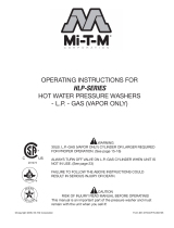
HHM FEATURES
HHM FEATURES-102006-PO

Operator's Manual 9
FEATURES LISTING
SPECIFIC UNIT INFORMATION
FRAME: Solid steel axles, push/pull handle with rubber grip.
PORTABILITY: Four pneumatic tires for easy mobility.
FINISH: Powder coated chassis with stainless steel heat exchanger.
1. Control Panel
2. Decal- Warning/Caution/Operation
3. Power Switch
4. Adjustable Thermostat
5. Power Cord w/GFCI
6. Hang Tag- Warning: Risk of Electrocution
7. Decal- Mi-T-M Stripe W/Logo
8. Decal- Data Plate
9. Decal-Caution: Risk of Fire
10. Burner Fuel Tank
11. Wheels
12. Brake
13. Access Panel
14. Push/Pull Handle
15. Stack Adapter Kit (Optional)
16. Heat Exchanger Exhaust
17. Decal- Warning: Hot Surface
18. Burner Protective Cover
19. Water Outlet
20. Burner Air Adjustment
21. High Pressure Jumper Hose
22. Fuel Filter
23. Water Inlet
24. Flow Switch

10 Operator's Manual
SETUP:
1. This unit should only be placed on a level surface. NEVER spray water
directly on the unit.
2. Do not use unit in an area:
a. with insufcient ventilation.
b. where there is a combustible cealing, unless suitable stack venting is
installed.
c. where there is evidence of oil or fuel leaks.
d. where ammable gas vapors may be present.
3. Be certain to engage the brake to prevent the unit from moving while
operating. Allow sufcient clearances around unit for accessibility.
4. Do not allow the unit to be exposed to rain, snow or freezing temperatures.
If any part of the unit becomes frozen, excessive pressure may build up in
the unit which could cause it to burst resulting in possible serious injury to
the operator or bystanders.
ATTIRE:
Proper attire is essential to your safety. It is advised to utilize whatever means
necessary to protect eyes, ears, and skin. Additional safety attire (such as
respiratory mask) may be required when using detergent cleaning agents with
this heater module.
OPTIONAL STACK ADAPTER – VENTILATION INSTRUCTIONS
1. Installation of this unit, in an indoor or enclosed environment, should be
performed by a qualied HVAC technician. Additionally, venting must
conform to all local, state, and federal codes. Refer to NFPA 31 and CAN/
CSA B139-M91, where applicable.
2. Exhaust gases must not be vented into a wall, a ceiling, or a concealed
space of a building.
3. 8” ue pipe must be used to match the size of the stack adapter accessory.
The ue pipe should be kept as short as possible and be installed so that it
has a continuous rise to the chimney. Elbows must be kept to an absolute
minimum to maintain the forced air draft in the system and ensure good
burn quality.
4. If the unit is being installed in an enclosed room, an adequate air supply
must be provided to burner by installing openings near the oor. These
openings should be at least one square inch per 1000 BTU input of the
machine. Also, a ventilation opening must be installed near the ceiling.
This opening should be at least the same size as the supply opening near
the oor. Refer to NFPA 31 and CAN/CSA B139-M91, where applicable.
5. If the burner is located in a tightly constructed building where there is
inadequate outside air inltration, outside combustion air must be supplied by
some other means. One method to accomplish this is through a permanent
opening, or openings, in an exterior wall. The total free area of the opening(s)
must not be less than one square inch per 5,000 BTU input. All appliances
must be taken into consideration. Refer to NFPA 31 and CAN/CSA B139-
M91, where applicable.
INSTALLATION & PREPARATION
WARNING
RISK OF ASPHYXIATION!
USE THIS PRODUCT ONLY IN
WELL VENTILATED AREAS! THE
EXHAUST CONTAINS CARBON
MONOXIDE, A POISONOUS,
ODORLESS AND INVISIBLE
GAS. BREATHING THIS GAS
CAN CAUSE SERIOUS INJURY,
ILLNESS & POSSIBLE DEATH.
DANGER
RISK OF EXPLOSION OR FIRE!
DO NOT PLACE UNIT IN AN
AREA WHERE FLAMMABLE
GAS VAPORS MAY BE PRESENT.
A SPARK COULD CAUSE AN
EXPLOSION OR FIRE!
RISK OF UNIT BURSTING!
DO NOT STORE/OPERATE UNIT
IN FREEZING ENVIRONMENTS!

Operator's Manual 11
INSTALLATION & PREPARATION
POWER CORD CONNECTION:
1. Make certain the power switch is in the "OFF" position.
2. Ensure electrical supply is identical to the specications listed on the
heater module data plate.
3. GROUNDING INSTRUCTIONS: This product must be grounded. If
it should malfunction or breakdown, grounding provides a path of
least resistance for electric current to reduce the risk of electric shock.
This product is equipped with a cord having an equipment-grounding
conductor. The plug must be plugged into an appropriate outlet that is
properly installed and grounded in accordance with all local codes and
ordinances.
4. DANGER: Improper connection of the equipment-grounding conductor
can result in a risk of electrocution. Check with a qualied electrician or
service personnel if you are in doubt as to whether the outlet is properly
grounded. Do not modify the plug - if it will not t the outlet, have a proper
outlet installed by a qualied electrician. Do not use any type of adaptor
with this product.
5. GROUND FAULT CIRCUIT INTERRUPTER PROTECTION: This heater
module is provided with a Ground Fault Circuit Interrupter (GFCI) built into
the plug or the power supply cord, test the GFCI each time it is plugged
into an outlet according to instructions on the GFCI. DO NOT use the
heater module if the test fails! The GFCI provides additional protection
from the risk of electric shock. Should replacement of the plug or cord
become necessary, use only identical replacement parts that include
GFCI protection.
6. EXTENSION CORDS: THE MANUFACTURER DOES NOT
RECOMMEND THE USE OF EXTENSION CORDS! If use of an
extension cord is unavoidable, it must be plugged into a GFCI found in
circuit boxes or protected receptacles. When using an extension cord,
consult a qualied electrician to determine the proper wire gauge needed
for the length of the extension cord.
Use only 3-wire extension cords that have 3-prong grounding-type plugs
and 3-pole cord connectors that accept the plug from the product.
Use only extension cords that are intended for outdoor use. These
extension cords are identied by a marking "Acceptable for use with
outdoor appliances; store indoors while not in use." Use only extension
cords having an electrical rating not less than the rating of the product.
Do not use damaged extension cords. Examine extension cord before
using and replace if damaged. Do not abuse extension cord and do
not pull on any cord to disconnect. Keep cord away from heat and
sharp edges. Always connect or disconnect the extension cord from
the receptacle before connecting or disconnecting the product from the
extension cord.
7. Ensure the area between the heater module cord and outlet is kept
dry.
8. Insert the male plug into a grounded AC outlet. DO NOT use an adapter
OR remove the grounding plug!!
DANGER
RISK OF ELECTROCUTION!
THIS UNIT MUST BE CONNECTED
TO A PROPERLY GROUNDED
OUTLET. DO NOT USE AN
ADAPTER OR REMOVE THE
THIRD GROUNDING PRONG.
WARNING
RISK OF ELECTROCUTION!
TO REDUCE THE RISK OF
ELECTROCUTION, KEEP ALL
CONNECTIONS DRY AND OFF
THE GROUND. DO NOT TOUCH
PLUG WITH WET HANDS.

12 Operator's Manual
INSTALLATION & PREPARATION
BURNER FUEL TANK:
1. Review "Risk of Explosion or Fire" pg. 5, before fueling.
2. Locate the Safety Decals on your unit and heed their warnings.
3. Fill the burner fuel tank with good quality, clean No. 1 or No. 2 fuel oil/diesel
or kerosene. Do not use gasoline!
PRE-START INSPECTION PROCEDURES:
Before starting the unit, perform the following procedures:
1. Inspect the electrical cords for cuts. If a cut is found, DO NOT TOUCH OR
USE CORD! Replace cord before starting unit.
2. Check all hose connections to ensure they are securely tightened.
3. Inspect for system water leaks, oil leaks and fuel leaks. If a fuel leak is
found, DO NOT START UNIT! See "Risk of Explosion or Fire", pg. 5. Be
sure that all damaged parts are replaced and that the mechanical problems
are corrected prior to operation of the unit. If you require service, contact
Customer Service.
WARNING
RISK OF EXPLOSION OR FIRE!
ALWAYS STORE FUEL AWAY
FROM THE HEATER MODULE
WHILE THE UNIT IS RUNNING
OR HOT.
DANGER
RISK OF FIRE!
-D O NO T SM OKE WHI LE
FUELING!
-DO NOT FILL THE FUEL TANK
WHILE UNIT IS RUNNING OR
HOT. ALLOW UNIT TO COOL
FOR TWO MINUTES BEFORE
REFUELING.
-DO NOT FILL FUEL TANK TO
POINT OF OVERFLOWING.

Operator's Manual 13
WARNING
THE FOLLOWING PAGES CONTAIN OPERATING AND
MAINTENANCE INSTRUCTIONS.
DO NOT ATTEMPT TO OPERATE THIS HEATER MODULE
UNTIL YOU HAVE READ AND UNDERSTOOD ALL THE
SAFETY PRECAUTIONS AND INSTRUCTIONS LISTED
IN THIS MANUAL.
INCORRECT OPERATION OF THIS UNIT CAN CAUSE
SERIOUS INJURY!!
DO NOT ALTER OR MODIFY THIS EQUIPMENT
IN ANY MANNER!

14 Operator's Manual
CAUTION
RISK OF DAMAGE.
DO NOT ALLOW SPRAY PATTERN
TO REMAIN ON A FIXED AREA
FOR AN EXTENDED PERIOD OF
TIME. POSSIBLE DAMAGE MAY
OCCUR TO THE AREA.
DANGER
RISK OF INJECTION CAUSING
SEVERE INJURY!
-KEEP CLEAR OF NOZZLE! NEVER
PLACE HAND OR FINGERS IN
FRONT OF NOZZLE!
-DO NOT DIRECT DISCHARGE
STREAM AT PEOPLE OR PETS!
-THIS PRODUCT IS TO BE
USED ONLY BY TRAINED
OPERATORS.
OPERATING INSTRUCTIONS
FLUSHING THE SYSTEM:
This unit has a steel coil which, after setting, will cause the water remaining in
the coil from the previous usage to turn brown or black. This water must be
ushed from the system before start-up. This procedure should be performed
without the high pressure hose, gun and dual lance assembly installed.
1. Turn on the water supply.
2. Move the power switch to the "ON" position. Low pressure water will begin
owing from the water outlet. This allows the unit to ush any particles from
the system. The unit is ushed when the water is clear.
3. Once the system is ushed, move the power switch to the "OFF" position
and connect the high pressure hose to the water outlet of the unit.
4. Connect the trigger gun, dual lance assembly and high pressure hose to
the unit.
START-UP / HOT WATER OPERATION:
1. Refer to the "Safety Warnings" pgs. 4-7 before starting the unit.
2. Locate the Safety Decals on your unit and heed their warnings.
3. Ensure that the power switch is in the "OFF" position.
4. Pointing the trigger gun in a safe direction, unlock the trigger gun and
squeeze the trigger. Brace yourself for possible gun kickback when the
pump starts.
5. Move the power switch to the "ON" position.
6. Once the unit has started, perform the following procedures with the gun
open:
a. Inspect for system water leaks, oil leaks and fuel leaks.
If a leak is found, TURN UNIT OFF IMMEDIATELY! Be sure that all
damaged parts are replaced and that the mechanical problems are
corrected prior to operation of the unit. If you require service, contact
Customer Service.
b. Inspect high pressure hoses for kinking, cuts and leaks.
If a cut or leak is found, DO NOT TOUCH HOSE AT LEAK!!! TURN UNIT
OFF IMMEDIATELY! Replace hose before starting the unit. See "Risk
of Injection or Severe Cutting Injury" pg. 6. Be sure that all damaged
parts are replaced and that the mechanical problems are corrected
prior to operation of the unit. If you require service, contact Customer
Service.
7. If hot water operation is desired, move the adjustable thermostat clockwise
to the desired setting.
At this point, the unit will operate as a hot water pressure washer. Be extremely
cautious when adjusting the pressure and controlling the trigger gun/dual lance
assembly to avoid the possibility of burns.
WARNING
RISK OF BURN!
THE WATER TEMPERATURE
C O U L D B E C O M E V E RY
H O T D U R I N G H O T
WAT ER OP ER AT IO N. B E
CAUTIOUS WHEN ADJUSTING
PRESSURE OR CONTROLLING
THE TRIGGER GUN/DUAL LANCE
ASSEMBLY.
CAUTION
RISK OF UNIT DAMAGE.
BE CERTAIN THE HOSE, GUN
& DUAL LANCE ASSY. ARE
NOT CONNECTED TO THE
UNIT WHILE FLUSHING THE
SYSTEM. FLUSHING ALLOWS
MINERAL DEPOSITS TO BE
RELEASED FROM THE SYSTEM
WHICH WOULD OBSTRUCT
OR DAMAGE THE GUN AND
NOZZLE ASSEMBLY RESULTING
IN COSTLY REPAIRS.
DANGER
RISK OF INJECTION CAUSING
SEVERE INJURY!
-TO PREVENT ACCIDENTAL HIGH
PRESSURE DISCHARGE, DO
NOT LEAVE UNIT UNATTENDED
UNTIL ALL THE SWITCHES ARE
IN THE OFF POSITION.
SHUTDOWN:
1. Turn the thermostat to the "OFF" position.
2. Squeeze the trigger and discharge the water for a period of three minutes
to cool the heat exchanger and high pressure hose. (Insufcient cool down
period of the high pressure hose will cause excessive wear and eventual
rupturing of the hose.)
3. Turn the power switch "OFF".
4. Turn off the water supply and trigger the gun momentarily to relieve
trapped pressure.
5. Disconnect and drain the high pressure hose, gun, and dual lance. Wipe
the unit clean store in a non-freezing environment.

Operator's Manual 15
MAINTENANCE CHART
PROCEDURE DAILY 3 MONTHS 6 MONTHS 9 MONTHS 12 MONTHS
Inspect electrical cord X
Test GFCI (according to instructions
on GFCI).
X
Fuel leak visual inspection X
Water leak visual inspection X
Hose visual inspection X
Fuel lter/water sep. inspection X
Check burner air adjustment X X X X
Test water temperature* X X X X
Replace fuel lter X X
Test fuel pressure* X
Delime coil** X
Test voltage and amp draw* X
Inspect fuel pump lter* X
Check burner electrodes* X
Replace fuel nozzle* X
* Should be performed by an authorized service technician.
** Scale build up will vary with mineral content in the water and amount of usage. Deliming can range from weekly
to yearly maintenance.
STORAGE & MAINTENANC

16 Operator's Manual
STORAGE & MAINTENANCE
MAINTENANCE-DAILY:
INSPECT ELECTRICAL CORD: Detach unit from power source and
inspect electrical cords to ensure they are free of cuts. If a cut is
found, replace cord before operating unit.
TEST GFCI: If applicable, test the GFCI. Testing varies according to
the specic GFCI. Follow the instructions given on the GFCI for
correct procedures.
FUEL LEAK INSPECTION: If a fuel leak is found, turn unit off immediately!
See "Risk of Explosion or Fire", pg. 5. Be sure that all damaged parts
are replaced and that the mechanical problems are corrected prior
to operation of the unit. If you require service, contact Customer
Service.
WATER LEAK INSPECTION: If a leak is found, promptly eliminate any
leaks found in the pumping system by removing suspect parts, applying
thread sealant to the threads and reinstalling. If using teon tape, be
certain no tape gets inside any plumbing to prevent the possibility of
a plugged spray nozzle. Be sure that all damaged parts are replaced
and that the mechanical problems are corrected prior to operation of
the unit. If you require service, contact Customer Service.
HOSE INSPECTION: Inspect high pressure hoses for kinking, cuts
and leaks. If a cut or leak is found, DO NOT USE HOSE! Replace
hose before starting unit. See "Risk of Injection or Severe Cutting
Injury", pg. 6. Be sure that all damaged parts are replaced and that
the mechanical problems are corrected prior to operation of the unit.
If you require service, contact Customer Service.
QUICK COUPLERS INSPECTION: There are o-ring seals inside the
couplers which will deteriorate. To replace, simply install a replacement
o-ring to correct the leak. (Additional o-rings can be purchased from
your dealer.)
FUEL FILTER/WATER SEPARATOR: Inspect bowl on fuel lter/water
separator for water accumulation. If water exists, unscrew drain
valve on bowl to drain water, then close.

Operator's Manual 17
MAINTENANCE-EVERY 3 MONTHS:
BURNER AIR ADJUSTMENT: The air shutter has been factory preset for
proper operation between sea level and 2000 feet elevation at
standard conditions (60°F ambient water and air temperatures).
In colder temperatures or higher altitudes, it may be necessary to
adjust the air supply to the combustion chamber. This adjustment
will maximize burner efciency and avoid inefcient operation or
excessive sooting of the heat exchanger coil. A smoke spot test
is recommended during any air shutter and band adjustment. If
you do not have the equipment to perform a smoke spot test,
follow the procedures listed below.
1. Turn the power switch on.
2. Loosen the Locking Screw (#3 at left) on the shutter.
3. Check for smoke from the heat exchanger exhaust. If smoke is
not present, slowly close the Air Shutter (#1 at left) by moving the
dial counterclockwise to a lower number. Continue moving the
dial until smoke appears.
4. Record this setting.
5. Open Air Shutter (#1 at left) two increments. Example: If Air
Shutter was set at 2, move it to 4.
6. Slowly trigger the gun on and off. This will cause the burner to
turn on and off. Look for a smoke puff when the burner ignites.
7. Repeat steps 5 and 6 until a smoke puff is noticed. Record the
Air Shutter Setting.
8. The difference between the recorded settings in steps 4 and 7
is the combustion window. Set the dial 1/2 way between these
settings.
NOTE: If you are unable to detect a setting on either step 3 or 7, more or less
air may be needed to achieve a proper combustion window. Loosen
the Bolt (#4 at left) and open the Air Band (#2 at left) in 1/4" increments.
Repeat steps 3-8 until proper combustion window is achieved.
TEST WATER & FUEL PRESSURE: These procedures should be
performed by an authorized service technician.
TEST WATER TEMPERATURE: This procedure should be performed by
an authorized service technician.
MAINTENANCE-EVERY 6 MONTHS:
REPLACE FUEL FILTER: Follow the instructions specied on the fuel
lter for correct procedures.
STORAGE & MAINTENANCE

18 Operator's Manual
MAINTENANCE-EVERY 12 MONTHS:
DELIME COIL: A loss in pressure may signify that the coil needs to be
delimed. Do this procedure on a periodic basis.
1. Mix deliming powder/solution according to package directions.
2. Remove the nozzle from the wand. Place a nylon stocking over the
wand assembly to collect debris, then place the wand assembly into
the oat tank.
3. Turn the switch to the "ON" position. Water will circulate throughout
the system and back into the oat tank. Allow circulation to continue
for 2-4 hours.
4. Turn the switch to the "OFF" position. Drain and clean the oat
tank. Remove nylon stocking and clean wand assembly.
5. Flush the entire system with clean, fresh water, then replace nozzle
into wand assembly.
6. Dispose of deliming solution according to local, state and national
regulations.
TEST VOLTAGE & AMP DRAW: Use a volt meter and amp meter to test
the machine for correct voltage and amperage. If you do not have these
instruments or do not know how to use them, this procedure should be
performed by an authorized service technician.
INSPECT FUEL PUMP INTERNAL FILTER: This procedure should be
performed by an authorized service technician.
CHECK BURNER ELECTRODES: This procedure should be performed
by an authorized service technician.
REPLACE FUEL NOZZLE: This procedure should be performed by an
authorized service technician.
CLEAN FUEL PICKUP INLET SCREEN: This procedure should be performed
by an authorized service technician.
MAINTENANCE-SEASONAL:
For storage and transportation purposes in subfreezing ambient temperatures, it
will be necessary to winterize this unit. This unit must be protected to the lowest
incurred temperature for the following reasons:
1. If any part of the water handling system becomes frozen; excessive
pressure may build up in the unit which could cause the unit to burst
resulting in possible serious injury to the operator or bystanders.
2. The water handling system in this unit may be permanently damaged if
frozen. FREEZE DAMAGE IS NOT COVERED BY WARRANTY.
If you must store your unit in an area where the temperature may fall below
32°F, you can protect your unit by following the procedure outlined below.
AIR BLOW OUT:
1. Remove the nozzle from the wand assembly. Squeeze the trigger
until water ceases to exit the wand assembly.
2. Connect an air tting from an air hose to the heater module inlet.
3. Run compressed air into the system to remove all water from the
system.
STORAGE & MAINTENANCE
WARNING
RISK OF UNIT BURSTING.
DO NOT STORE / OPERATE
U NI T I N A FR EE Z I NG
ENVIRONMENT!
32˚F 0˚C

Operator's Manual 19
TROUBLESHOOTING
SYMPTOM PROBABLE CAUSE REMEDY
Motor will not run. GFCI tripped. Reset.
No discharge at nozzle when Inadequate water supply. Ensure hose is 3/4" diameter and
trigger mechanism is squeezed. incoming water supply is turned on.
Low or uctuating pressure. Kink in water inlet hose. Remove kink.
Kink in high pressure discharge hose. Replace kinked high pressure hose.
Scale build up in heat exchanger coil. Delime coil.
Burner will not ignite Switch is defective. Check switch position or replace.
Adjustable Thermostat is defective Check switch position or replace.
or in the "Off" position.
No voltage. Contact Customer Service.
Out of fuel. Refuel.
Fuel tank inlet tube screen obstructed. Remove, clean or replace tube.*
Trigger gun is closed. Open trigger gun for pressure.
Pressure switch override. Pressure should be over 250 PSI/
15 Bar to allow burner to come on.
(Pressure should be checked by an
authorized service technician.)
Fuel pickup screen is obstructed. Contact Customer Service.
Temperature above thermostat Unit will automatically reignite when
setting. cool.
High limit switch override. Unit will automatically reignite when
cool.
Flexible coupler broken. Replace.*
Dirty or clogged fuel lter. Drain or replace as necessary.*
Fuel pump sucking air. Tighten all fuel intake connections.
Eliminate leaks in intake line.
Fuel pump inoperative. Check pressure, replace if needed.
(Pressure should be checked by an
authorized service technician.)
Dirty or clogged fuel nozzle. Replace.*
Improper burner air adjustment. Adjust.
Ignition transformer failure. Replace.*
Ignition electrodes not set properly, Contact Customer Service.
damaged or worn.
Fuel solenoid valve failure. Replace.*
*See separate Parts List for detailed views or explanations.

20 Operator's Manual
Burner motor will not run. Switch is defective position. Check switch position or replace.
No voltage. Contact Customer Service.
Motor overload. Reset when cool.
Fuel pump seized. Allow motor to cool. Repair or
replace.*
Burner runs erratically. Water in the fuel oil. Drain fuel lter/water separator.
Drain fuel tank, and replace with
clean fuel.
Dirty fuel lter/water separator. Replace element.
Fuel pickup screen is obstructed. Contact Customer Service.
Dirty fuel nozzle. Replace.*
Improper air adjustment setting. Adjust.
Fuel pump malfunctioning. Replace.*
Burner runs, but will not heat. Low fuel pump pressure. Check fuel pump pressure, adjust or
replace if needed. (Pressure should
be checked by an authorized
service technician.)
Dirty fuel nozzle. Replace.*
Improper air adjustment setting. Adjust.
Burner discharges white smoke. Low on fuel. Refuel. If white smoke persists,
contact Customer Service.
Low fuel pressure. Check fuel pump pressure, adjust or
replace if needed. (Pressure should
be checked by an authorized
service technician.)
Fuel pickup screen is obstructed. Contact Customer Service.
Dirty fuel nozzle. Replace.*
Improper air adjustment setting. Adjust.
Cold combustion chamber start-up. Run burner for several minutes.
Excessive air supply. Adjust.
Burner discharges black smoke. Insufcient air supply. Adjust.
Fuel nozzle orice is too large. Replace with correct nozzle.
Fuel pressure is too high. Contact Customer Service.
Combustion chamber loaded with Contact Customer Service.
unburned fuel.
*See separate Parts List for detailed views or explanations.
TROUBLESHOOTING
SYMPTOM PROBABLE CAUSE REMEDY
/