Miller Coolmate 1 Owner's manual

Category
Welding System
Type
Owner's manual

This manual is also suitable for

OWNER’S MANUAL
© 2010 MILLER Electric Mfg. Co.
OM-235 464F
201004
CE And Non-CE Models
Coolmate 1
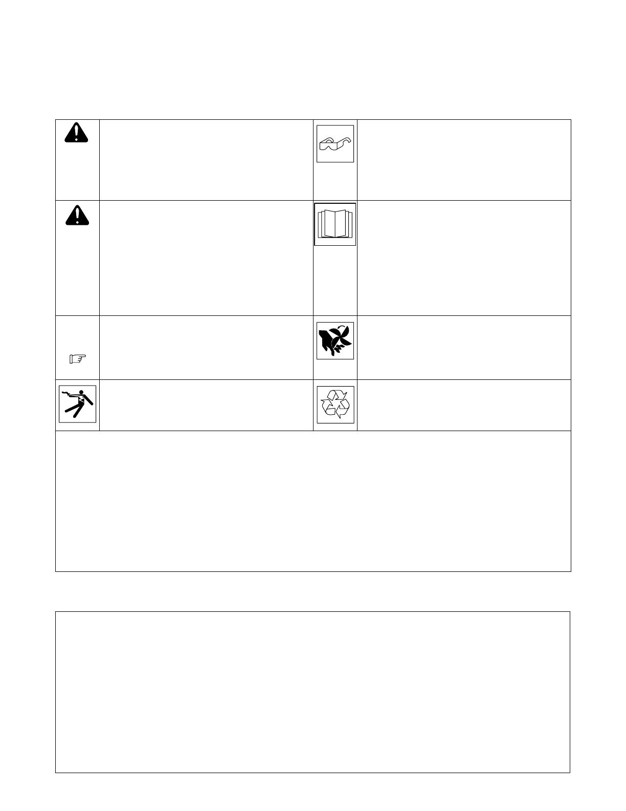
1. Safety Symbol Definitions
DANGER! Indicates a hazardous situation which, if not
avoided, will result in death or serious injury. The possible
hazards are shown in the adjoining symbols or explained
in the text.
DANGER! Indique une situation dangereuse qui si on
l’évite pas peut donner la mort ou des blessures graves.
Les dangers possibles sont montrés par les symboles
joints ou sont expliqués dans le texte.
Wear safety glasses with side shields.
Porter des lunettes de sécurité avec des protections laté-
rales.
Indicates a hazardous situation which, if not avoided,
could result in death or serious injury. The possible ha-
zards are shown in the adjoining symbols or explained in
the text.
Indique une situation dangereuse qui si on l’évite pas peut
donner la mort ou des blessures graves. Les dangers possi-
bles sont montrés par les symboles joints ou sont expliqués
dans le texte.
Have only trained and qualified persons install, operate,
or service this unit. Call your distributor if you do not un-
derstand the directions. For WELDING SAFETY and
EMF information, read owner’s manual(s).
L’installation, l’exploitation et l’entretien de cet appareil
doivent être confiés uniquement à des personnes quali-
fiées et convenablement formées. S’adresser à un distri-
buteur si l’on ne comprend pas les directives. Pour les
renseignements ayant trait à la SECURITE lors du sou-
dage et aux champs électromagnétiques, consulter les
manuels traitant les dévidoirs et les sources de courant
pour le soudage.
NOTICE
Indicates statements not related to personal injury.
Indique des déclarations pas en relation avec des blessu-
res personnelles.
Indicates special instructions.
Indique des instructions spécifiques.
Beware of moving parts. Keep guards and panels in
place, covers closed, and hands away from moving parts.
Attention aux pièces mobiles. Maintenir les dispositifs de
sécurité et les panneaux en place, les couvercles fermés
et garder les mains éloignées des pièces mobiles.
Beware of electric shock from wiring. Reinstall all panels
and covers.
Risque d’électrocution due au contact avec des fils. Réin-
staller tous les panneaux et couvercles.
Recycle or dispose of used coolant in an environmentally
safe way.
Recycler ou éliminer tout liquide de refroidissement usé
conformément aux méthodes prescrites pour assurer la
protection de l’environnement.
CALIFORNIA PROPOSITION 65 WARNINGS
Welding or cutting equipment produces fumes or gases which contain chemicals known to the State of California to cause birth defects
and, in some cases, cancer. (California Health & Safety Code Section 25249.5 et seq.)
This product contains chemicals, including lead, known to the state of California to cause cancer, birth defects, or other reproductive
harm. Wash hands after use.
Avertissements issus de la «Proposition 65»
Les équipements de soudage ou de coupe produisent des émanations ou des gaz qui contiennent des agents chimiques réputés selon
l’État de Californie causer des déficiences congénitales et, dans certains cas, le cancer. (Section 25249.5 et suivantes du «California
Health & Safety Code»)
Ce produit contient des agents chimiques, notamment du plomb, réputés selon l’État de Californie causer des cancers, des malforma-
tions congénitales ou d’autres problèmes de procréation. Se laver les mains après utilisation.
2. EMF Information
Electric current flowing through any conductor causes localized elec-
tric and magnetic fields (EMF). Welding current creates an EMF field
around the welding circuit and welding equipment. EMF fields may in-
terfere with some medical implants, e.g. pacemakers. Protective
measures for persons wearing medical implants have to be taken. For
example, access restrictions for passersby or individual risk assess-
ment for welders. All welders should use the following procedures in
order to minimize exposure to EMF fields from the welding circuit:
1. Keep cables close together by twisting or taping them, or using
a cable cover.
2. Do not place your body between welding cables. Arrange
cables to one side and away from the operator.
3. Do not coil or drape cables around your body.
4. Keep head and trunk as far away from the equipment in the
welding circuit as possible.
5. Connect work clamp to workpiece as close to the weld as
possible.
6. Do not work next to, sit or lean on the welding power source.
7. Do not weld whilst carrying the welding power source or wire
feeder.
About Implanted Medical Devices:
Implanted Medical Device wearers should consult their doctor and the
device manufacturer before performing or going near arc welding,
spot welding, gouging, plasma arc cutting, or induction heating opera-
tions. If cleared by your doctor, then following the above procedures
is recommended.
OM-235 464 Page 2
3. Important Information Regarding CE Products (Sold Within The EU)
! This equipment shall not be used by the general public as the EMF limits for the general public might be exceeded during welding.
This equipment is built in accordance with EN 609741 and is intended to be used only in an occupational environment (where the general public
access is prohibited or regulated in such a way as to be similar to occupational use) by an expert or an instructed person.
Wire feeders and ancillary equipment (such as torches, liquid cooling systems and arc striking and stabilizing devices) as part of the welding
circuit may not be a major contributor to the EMF. See the Owner’s Manuals for all components of the welding circuit for additional EMF exposure
information.
S The EMF assessment on this equipment was conducted at 0.5 meter.
S At a distance of 1 meter the EMF exposure values were less than 20% of the permissible values.
4. Specifications
Recirculating Coolant System For Water-Cooled GTAW Torches And GMAW Guns
Used Primarily With Maxstar 200®, Dynasty 200®, And Syncrowave® 200 Models
IP Rating: 23 Not Intended For Use In Heavy Rain, Or Near Splashing Water
1 gal (3.8 L) Coolant System Capacity
Max Cooling Capacity: 9700 BTU/hr (2850 Watts) @ 1.7 L/min
IEC Cooling Capacity: 4120 BTU/hr (1210 Watts) @ 1L/min
IEC Cooling Capacity states that the water inlet temperature can not exceed 40° C above ambient temper-
ature at a 1L/min flow rate.
Max Welding Amperage Rating: 200 amps @ 40% duty cycle, 175 amps @ 60% duty cycle, 150 amps
@ 100% duty cycle.
Dimensions: 23-3/4 in. (603 mm) Long, 7-1/2 in. (191 mm) Wide, 8 in. (203 mm) High
Weight: 25 lb (11 kg)
115 Volt Models Use 2.1 Amperes, 60 Hertz, Single-Phase Input Power; 230 Volt Models Use 0.65 Am-
peres, 50/60 Hertz, Single-Phase Input Power
5. Serial Number And Rating Label Location
The serial number and rating information for this product is located on the back panel. Use rating label to determine input power requirements and/or
rated output. For future reference, write serial number in space provided on cover of this manual.
OM-235 464 Page 3
6. Warning Label Definitions For CE Products
S-180 663
1 2 3 4 5
6
7 8 9
1 Warning! Watch Out! There are
possible hazards as shown by the
symbols.
2 Electric shock from wiring can kill.
3 Disconnect input plug or power before
working on machine.
4 Moving parts, such as fans, can cut
fingers and hands and cause injury.
Keep away from moving parts.
5 Wear safety glasses with side shields.
6 Read the Owner’s Manual before
working on this machine.
7 Read the labels on the welding power
source, wire feeder, or other major
equipment for welding safety
information.
8 Recycle or dispose of used coolant in
an environmentally safe way.
9 Do not remove or paint over (cover)
the label.
4/96
S-178 910
=
043 810 (HF)
043 809 (AL)
100 h. std.
21 3
6
4
7
5
1 Warning! Watch Out! There are
possible hazards as shown by the
symbols.
2 Disconnect input plug or power before
working on machine.
3 Wear safety glasses with side shields.
4 Plugged filter or hoses cause
overheating and damage.
5 Read Owner’s Manual.
6 Check and clean filter every 100
hours; also check condition of hoses.
7 Use Low Conductivity Coolant No. 043
810 for High-Frequency assisted or
Gas Tungsten Arc Welding
applications. Use Aluminum Protecting
Coolant No. 043 809 where coolant
contacts aluminum parts or for Gas
Metal Arc Welding applications or
where High Frequency is not used.
OM-235 464 Page 4
7. Symbols And Definitions
Hz
Hertz Input Power Power On Indicator
Water (Coolant)
Output
Water (Coolant) In-
put
Line Connection
Single-Phase
Alternating
Current
U
1
Primary Voltage
I
1max
Rated Maximum
Supply Current
IP
Degree Of
Protection
P
max
Rated maximum
power
Pl/
min
Power liters per
minute
8. WEEE Label (For Products Sold Within The EU)
Do not discard product (where ap-
plicable) with general waste.
Reuse or recycle Waste Electrical
and Electronic Equipment (WEEE)
by disposing at a designated collec-
tion facility.
Contact your local recycling office
or your local distributor for further
information.
9. Coolant Chart
Low Conductivity Coolant
No. 043 810**;
Distilled Or Deionized Water
OK Above 32° F (0° C)
Low Conductivity Coolant
No. 043 810**; Or
Aluminum Protecting Coolant
No. 043 809**;
Distilled Or Deionized Water
OK Above 32° F (0° C)
GTAW Or Where
HF* Is Used
GMAW Or Where
HF* Is Not Used
Application
*HF: High Frequency Current
**Coolants 043 810 and 043 809 protect to -37° F (-38°C) and resist algae growth.
Coolant
Aluminum Protecting
Coolant No. 043 809**
Where Coolant Contacts
Aluminum Parts
NOTICE Use of any coolant other than those listed in the table voids the warranty on any parts
that come in contact with the coolant (pump, radiator, etc.).
OM-235 464 Page 5
10. GTAW Connections
805 189-B
Tools Needed:
11/16 in.
1
2
3
4
To prevent overheating, make sure cooling
unit is positioned so there is 12 in. (305
mm) of unrestricted airflow on sides of unit.
NOTICE If welding power source has a
water valve, do not connect hoses to water
valve. Connect hoses as shown.
1 Coolant Out Hose
2 Coolant In Hose
Fittings have 5/8-18 left-hand threads.
Connect hoses with proper fittings as
shown. Some power sources may require
a TIG block.
3 Coolant Tank Cap
4 115 Or 230 Volt AC Grounded Re-
ceptacle (Depending On Model)
NOTICE Do not cut plug from 115 volt
cord and attempt to rewire for 230 volts, or
do not cut plug from 230 volt cord and at-
tempt to rewire for 115 volts.
For 115 volt models, an individual branch
circuit capable of carrying 15 amperes and
protected by fuses or circuit breakers is
recommended. Recommended fuse or cir-
cuit breaker size is 15 amperes. For 230
volt models, an individual branch circuit ca-
pable of carrying 10 amperes and pro-
tected by fuses or circuit breakers is rec-
ommended. Recommended fuse or circuit
breaker size is 10 amperes.
Operation:
. You may experience pump/priming
noise during initial start-up, or after
changing or replacing coolant.
Fill tank with proper coolant. Use table in
Section 9 to select proper coolant. Maintain
coolant level at approximately 1 in (25 mm)
below top of filler neck. Connect hoses as
shown. Unit turns on when plugged in and
power switch is turned on.
. For correct water cooled torch ad-
apters, see Parts List or the Coolmate
Series Options And Accessories
page.
OM-235 464 Page 6
11. GMAW Connections
805 190-B
Tools Needed:
11/16 in.
To prevent overheating, make sure cooling
unit is positioned so there is 12 in. (305
mm) of unrestricted airflow on sides of unit.
NOTICE If welding power source has a
water valve, do not connect hoses to water
valve. Connect hoses as shown.
1 Coolant Out Hose
2 Coolant In Hose
Fittings have 5/8-18 left-hand threads.
Connect hoses with proper fittings as
shown.
3 Coolant Tank Cap
4 115 Or 230 Volt AC Grounded Re-
ceptacle (Depending On Model)
NOTICE Do not cut plug from 115 volt
cord and attempt to rewire for 230 volts, or
do not cut plug from 230 volt cord and at-
tempt to rewire for 115 volts.
An individual branch circuit capable of car-
rying 15 amperes and protected by fuses
or circuit breakers is recommended. Rec-
ommended fuse or circuit breaker size is
15 amperes. For 230 volt models, an indi-
vidual branch circuit capable of carrying 10
amperes and protected by fuses or circuit
breakers is recommended. Recom-
mended fuse or circuit breaker size is 10
amperes.
Operation:
. You may experience pump/priming
noise during initial start-up, or after
changing or replacing coolant.
Fill tank with proper coolant. Use table in
Section 9 to select proper coolant. Maintain
coolant level at approximately 1 in (25 mm)
below top of filler neck. Connect hoses as
shown. Unit turns on when plugged in and
power switch is turned on.
2
1
3
4
OM-235 464 Page 7
12. Routine Maintenance
! Disconnect power
before maintaining.
n = Check Z = Change ~ = Clean Δ = Repair l = Replace
* To be done by Factory Authorized Service Agent
Every
3
Months
~Coolant Filter, durning heavy
service, clean more frequently.
~ Blow out heat exchanger fins.
nCheck coolant level. Top off with
distilled or deionized water if necessary.
Every
6
Months
nlHoses
nl Labels
ZReplace coolant.
13. Coolant Maintenance
805 191-A
! Disconnect input power be-
fore maintaining.
NOTICE Do not run cooler with-
out coolant in tank.
1 Coolant Filter
Unscrew housing to clean filter (see
Section 12).
Assemble and install cleaned cool-
ant filter.
. Dispose of used coolant and
fluids in an environmentally
safe way.
Changing coolant: Drain coolant by
removing cap and tipping unit for-
ward, or use suction pump. Fill with
clean water and run for 10 minutes.
Drain and refill with coolant (see
section 9). Install cap.
. If replacing hoses, use hoses
compatible with ethylene gly-
col, such as Buna-n, Neo-
prene, or Hypalon. Oxy-acety-
lene hoses are not compatible
with any product containing
ethylene glycol.
1
OM-235 464 Page 8
14. Troubleshooting
Trouble Remedy
Excessive noise.
Pump priming noise can occur during startups, or after changing or replacing coolant. Noise will subside
after pump is primed. Tighten filter cap if noise persists.
Have Factory Authorized Service Agent check unit if motor is hitting divider mid-plane.
Coolant system does not work. Be sure input power cord is plugged into an energized receptacle, and power is turned on.
Check line fuses or circuit breaker, and replace or reset if necessary.
Motor overheated. Unit starts running when motor has cooled.
Have Factory Authorized Service Agent check Power switch S1 and motor (Mot).
Decreased or no coolant flow.
Add coolant.
Check for clogged hoses or coolant filter. Clean filter or clean / replace hoses if necessary.
15. Circuit Diagram For Cooler
235 469-A
OM-235 464 Page 9
Notes
OM-235 464 Page 10
SECTION 16 PARTS LIST
. Hardware is common and
not available unless listed.
805 266-A
1
2
3
4
5
13
6
8
7
12
9
10
12
11
13
6
15
14
13
6
14
18
17
21
22
23
24
18
26
25
20
19
16
27
Figure 16-1. Main Assembly
OM-235 464 Page 11
Quantity
Description
Part
No.
Dia.
Mkgs.
Item
No.
Figure 16-1. Main Assembly
1 +235416 Wrapper, . . . . . . . . . . . . . . . . . . . . . . . . . . . . . . . . . . . . . . . . . . . . . . . . . . . . . . . . . . . . . . . . . . . . . . .
2 188980 Label, Caution Incorrect Coolant (Non-CE Models) 1. . . . . . . . . . . . . . . . . . . . . . . . . . . . . . . . . . .
2 178910 Label, Caution Incorrect Coolant (CE Models) 1. . . . . . . . . . . . . . . . . . . . . . . . . . . . . . . . . . . . . . . .
3 203990 Label, Warning General Precautionary Static (Non-CE Models) 1. . . . . . . . . . . . . . . . . . . . . . . . .
3 180663 Label, Warning General Precautionary Static (CE Models) 1. . . . . . . . . . . . . . . . . . . . . . . . . . . . .
4 235422 Tank, Coolant 1. . . . . . . . . . . . . . . . . . . . . . . . . . . . . . . . . . . . . . . . . . . . . . . . . . . . . . . . . . . . . . . . . . . .
5 166608 Cap, Tank Screwon W/Vent 1. . . . . . . . . . . . . . . . . . . . . . . . . . . . . . . . . . . . . . . . . . . . . . . . . . . . . .
6 237535 Hose, Rbr Brd No 1 X .375 ID X 2.250 Black 3. . . . . . . . . . . . . . . . . . . . . . . . . . . . . . . . . . . . . . . . .
7 166564 Filter, Inline Low Profile 100 Screen 3/8 Hose Bar 1. . . . . . . . . . . . . . . . . . . . . . . . . . . . . . . . . . .
8 235419 Bracket, Filter 1. . . . . . . . . . . . . . . . . . . . . . . . . . . . . . . . . . . . . . . . . . . . . . . . . . . . . . . . . . . . . . . . . . . .
9 FM 213072 Fan, Muffin 115V 60 Hz 3400 RPM 6.378 Mtg Holes 1. . . . . . . . . . . . . . . . . . . . . . . . . . . . .
9 FM 235504 Fan, Muffin 230V 60 Hz 3400 RPM 6.378 Mtg Holes 1. . . . . . . . . . . . . . . . . . . . . . . . . . . . .
10 235418 Divider 1. . . . . . . . . . . . . . . . . . . . . . . . . . . . . . . . . . . . . . . . . . . . . . . . . . . . . . . . . . . . . . . . . . . . . . . . .
11 237543 Radiator, Heat Exchanger 1. . . . . . . . . . . . . . . . . . . . . . . . . . . . . . . . . . . . . . . . . . . . . . . . . . . . . . . .
12 237538 Hose, Rbr Brd No 1 X .375 ID X 18.000 Black 1. . . . . . . . . . . . . . . . . . . . . . . . . . . . . . . . . . . . . . .
13 237539 Hose, Rbr Brd No 1 X .375 ID X 11.50 Black 2. . . . . . . . . . . . . . . . . . . . . . . . . . . . . . . . . . . . . . . .
14 237536 Hose, Rbr Brd No 1 X .375 ID X 9.0 Black 1. . . . . . . . . . . . . . . . . . . . . . . . . . . . . . . . . . . . . . . . . .
15 235461 Damper, Fluid Pulsation 1. . . . . . . . . . . . . . . . . . . . . . . . . . . . . . . . . . . . . . . . . . . . . . . . . . . . . . . . . .
16 MOT 235457 Pump, Assy Coolant (115V) 1. . . . . . . . . . . . . . . . . . . . . . . . . . . . . . . . . . . . . . . . . . . . . . . .
16 MOT 235501 Pump, Assy Coolant (230V) 1. . . . . . . . . . . . . . . . . . . . . . . . . . . . . . . . . . . . . . . . . . . . . . . .
17 PLG1 192457 Cable, Power 11 Ft 7 In 16ga 3c (115V) 1. . . . . . . . . . . . . . . . . . . . . . . . . . . . . . . . . . . . .
17 PLG1 192458 Cable, Power 11 Ft 7 In 16ga 3c (230V) 1. . . . . . . . . . . . . . . . . . . . . . . . . . . . . . . . . . . . .
18 235423 Bezel, 2. . . . . . . . . . . . . . . . . . . . . . . . . . . . . . . . . . . . . . . . . . . . . . . . . . . . . . . . . . . . . . . . . . . . . . . . .
19 240279 Valve, Check 3/8 Barb Inline 1. . . . . . . . . . . . . . . . . . . . . . . . . . . . . . . . . . . . . . . . . . . . . . . . . . . . . .
20 094263 Clamp, 1ear Type Nom Dim .718 X .276 Wide 14. . . . . . . . . . . . . . . . . . . . . . . . . . . . . . . . . . . . .
21 235417 Panel, Rear 1. . . . . . . . . . . . . . . . . . . . . . . . . . . . . . . . . . . . . . . . . . . . . . . . . . . . . . . . . . . . . . . . . . . .
22 235415 Base, 1. . . . . . . . . . . . . . . . . . . . . . . . . . . . . . . . . . . . . . . . . . . . . . . . . . . . . . . . . . . . . . . . . . . . . . . . .
23 239388 Bumper, rbr .875 OD X .188 ID X .39 High Recessed 4. . . . . . . . . . . . . . . . . . . . . . . . . . . . . . . .
24 S1 237540 Switch, Rocker Dpst 16 A 115 VAC OnOff 1. . . . . . . . . . . . . . . . . . . . . . . . . . . . . . . . . . . . .
24 S1 237541 Switch, Rocker Dpst 16 A 230 VAC OnOff 1. . . . . . . . . . . . . . . . . . . . . . . . . . . . . . . . . . . . .
25 235499 Ftg, Coolant Barbed 3/8 Tbg 5/818 Female 2. . . . . . . . . . . . . . . . . . . . . . . . . . . . . . . . . . . . . . . .
26 Nameplate, Miller Coolmate 1 (Order By Model And Serial Number) 1. . . . . . . . . . . . . . . . . . . . . . . . . . . . .
27 287120 Label, Notice Pump Priming Noise Can Occur During 1. . . . . . . . . . . . . . . . . . . . . . . . . . . . . . . .
To maintain the factory original performance of your equipment, use only Manufacturers Suggested
Replacement Parts. Model and serial number required when ordering parts from your local distributor.
+When ordering a component originally displaying a precautionary label, the label should also be ordered.
12
DECLARATION OF CONFORMITY
for European Community (CE marked) products.
MILLER Electric Mfg. Co., 1635 Spencer Street, Appleton, WI 54914 U.S.A. declares that the
product(s) identified in this declaration conform to the essential requirements and provisions of
the stated Council Directive(s) and Standard(s).
Product/Apparatus Identification:
Product Stock Number
Coolmate 1 W/CE 300360001 & 300459001
Council Directives:
S 2006/95/EC Low Voltage
S 2004/108/EC Electromagnetic Compatibility
Standards:
S IEC 609741:2005 Arc welding equipment – Part 1: Welding power sources
S IEC 609742:2008 Arc welding equipment – Part 2: Liquid cooling systems
S IEC 6097410:2007 Arc Welding Equipment – Part 10: Electromagnetic compatibility (EMC) requirements
S EN 50445:2008 Product family standard to demonstrate compliance of equipment for resistance welding,
arc welding and allied processes with the basic restrictions related to human exposure to electromagnetic
fields (0 Hz – 300Hz)
US Signatory:
August 31, 2009
__________________________________________________________________________
David A. Werba
Date of Declaration
MANAGER, PRODUCT DESIGN COMPLIANCE
CS1000B
Notes
Notes
Notes
Work like a Pro!
Pros weld and cut
safely. Read the
safety rules at
the beginning
of this manual.
ORIGINAL INSTRUCTIONS PRINTED IN USA © 2010 Miller Electric Mfg. Co. 201001
Miller Electric Mfg. Co.
An Illinois Tool Works Company
1635 West Spencer Street
Appleton, WI 54914 USA
International HeadquartersUSA
USA Phone: 920-735-4505 Auto-Attended
USA & Canada FAX: 920-735-4134
International FAX: 920-735-4125
For International Locations Visit
www.MillerWelds.com
Model Name Serial/Style Number
Purchase Date (Date which equipment was delivered to original customer.)
Distributor
Address
City
State Zip
Please complete and retain with your personal records.
Always provide Model Name and Serial/Style Number.
Contact a DISTRIBUTOR or SERVICE AGENCY near you.
Welding Supplies and Consumables
Options and Accessories
Personal Safety Equipment
Service and Repair
Replacement Parts
Training (Schools, Videos, Books)
Technical Manuals (Servicing Information
and Parts)
Circuit Diagrams
Welding Process Handbooks
Contact the Delivering Carrier to:
For Service
Owner’s Record
File a claim for loss or damage during
shipment.
For assistance in filing or settling claims, contact
your distributor and/or equipment manufacturer’s
Transportation Department.
Contact your Distributor for:
To locate a Distributor or Service Agency visit
www.millerwelds.com or call 1-800-4-A-Miller
  • Page 1 1
  • Page 2 2
  • Page 3 3
  • Page 4 4
  • Page 5 5
  • Page 6 6
  • Page 7 7
  • Page 8 8
  • Page 9 9
  • Page 10 10
  • Page 11 11
  • Page 12 12
  • Page 13 13
  • Page 14 14
  • Page 15 15
  • Page 16 16

Miller Coolmate 1 Owner's manual

Category
Welding System
Type
Owner's manual
This manual is also suitable for

Ask a question and I''ll find the answer in the document

Finding information in a document is now easier with AI

in other languages