Toro 22162 User manual

Category
Lawnmowers
Type
User manual

This manual is also suitable for

Operators Manual
Manual del Operador
FORM NO. 3319–575
ProLine 21” Recycler II
Walk-behind Power Mower
Model No. 22162 — 8900001 & Up
ProLine 21” Recycler II
Cortadora de césped motorizada empujada por
el usuario
Modelos N. 22162 — 8900001 y siguientes
The engine exhaust from this product
contains chemicals known to the State of
California to cause cancer, birth defects,
or other reproductive harm.
WARNING:
El escape del motor de esta herramienta
contiene productos químicos que según
la información del Estado de California
producen cáncer, defectos congénitos u
otros riesgos reproductivos.
ADVERTENCIA:
EThe Toro Company – 1998
Printed in USA
All Rights Reserved
i
Figures — Figuras
224
1
English
1. Model and serial number decal
Español
1. Calcomanía con el modelo y el número de serie
534
1
2
3
4
English
1. Handle latch
2. Bag support rod
3. Cap locknut
4. Handle
Español
1. Pestillo de la manija
2. Varilla de sujeción del
saco
3. Contratuerca de cabeza
4. Manija
530
3
4
5
1
2
English
1. Tank bracket
2. Slots
3. Plastic clips
4. Gas tank
5. Self-tapping screw
Español
1. Soporte del tanque
2. Ranuras
3. Presillas de plástico
4. Tanque de gasolina
5. Tornillo autorroscante
1
2
3
Figures – Figuras
ii
1
3
2
2045
English
1. Fuel line clamp
2. Fuel line
3. Elbow fitting
Español
1. Abrazadera de la línea de
combustible
2. Línea de combustible
3. Racor angular
m–210
1
2
English
1. Rope guide 2. Starter rope
Español
1. Gula del cable 2. Cable del arrancador
m–262
2
1
English
1. Discharge door handle 2. Plug rotated clockwise
Español
1. Asa de la puerta de
descarga
2. Tapón girado hacia la
derecha
m–275
1
English
1. Spring clip
Español
1. Presilla de resorte
4
5
6
7
Figures – Figuras
iii
m–3845
1
2
3
4
English
1. Oil fill tube
2. Dipstick
3. ADD mark
4. FULL mark
Español
1. Tubo de llenado del aceite
2. Varilla de nivel
3. Repére “ADD” (agregar)
4. Marca “FULL” (lleno)
976
#4!4
#4!4#4!4
1992
1
2
3
English
1. Blade/self-propelled
control bar
2. Throttle
3. Fingertip starter
Español
1. Barra de control de la
cuchilla/autopropulsión
2. Control de aceleración
3. Arranque de recuperación
224
1
English
1. Ground speed control
Español
1. Control de velocidad sobre el terreno
8
9
10
11
Figures – Figuras
iv
m–3662
1 2
English
1. Primer 2. Spark plug wire
Español
1. Cebador 2. Cable de la bujia
m-3769



m–261
1
3
2
English
1. Bag frame on retaining
post
2. Pin engaged in catch
3. Handle fully forward.
Discharge door closed.
Español
1. Marco del saco en el
poste retenedor
2. Pasador en el enganche
3. Manija completamente
hacia adelante. Puerta de
descarga cerrada
m–260
1
English
1. Pin locked in bag notch
Español
1. Pasador trabado en la ranura del saco
12
13
14
15
Figures – Figuras
v
225
1
English
1. Height-of-cut adjuster
Español
1. Ajustador de la altura del corte
m–3664
1
2
3
4
English
1. Knob
2. Cover
3. Foam pre–cleaner
4. Paper cartridge
Español
1. Perilla
2. Tapa
3. Pre–filtro de espuma
4. Cartucho de papel
110
1
English
1. .030 in. (.76 mm)
Español
1. 0,76 mm (0,030 pulgadas)
m–3848
1
2
English
1. Oil fill tube 2. Oil filter
Español
1. Tubo de llenado del aceite 2. Filtro de aceite
16
17
18
19
Figures – Figuras
vi
m-3862
1
English
1. Gasket
Español
1. Junta
m-3638
English
1. Cable clamp screw
2. Governor control lever
3. Throttle cable
4. Casing
Español
1. Tornillo de la abrazadera
del cable
2. Palanca de control de
gobierno
3. Cable del acelerador
4. Envoltura
228
1
English
1. Control knob
Español
1. Perilla de control
1
m–1992
English
1. One inch
Español
1. Una pulgada
20
21
22
23
Figures – Figuras
vii
796
2
3
4
1
English
1. Blade
2. Blade nuts
3. Anti-scalp cup
4. Accelerator
Español
1. Cuchilla
2. Tuercas de la cuchilla
3. Cubeta antipelusa
4. Acelerador
270
1
1
1
2
3
4
English
1. Sail
2. Flat part of blade
3. Wear
4. Slot formed
Español
1. Aleta
2. Parte plana de la cuchilla
3. Desgaste
4. Ranura formada
153
1
English
1. Sharpen at this angle only
Español
1. Afile solamente a este ángulo
232
1
English
1. Grease fitting
Español
1. Copilla de engrase
24
25
26
27
Figures – Figuras
viii
224
1
2
English
1. Grease fitting 2. Belt cover
Español
1. Copilla de engrase 2. Tapa de la correa
278
1
2
3
English
1. Spring
2. Cable clamp screw
3. Cable conduit
Español
1. Resorte
2. Tornillo de la abrazadera
del cable
3. Conducto del cable
1093
English
1. Right rear wheel
Español
1. Rueda trasera derecha
m–3844
1
3
2
2
English
1. Hose clamp
2. Fuel line
3. Filter
Español
1. Abrazadera
2. Manquito de combustible
3. Filtro
28
29
30
31
Figures – Figuras
ix
796
1
English
1. Kicker plates
Español
1. Placas deflectoras
796
1
2
3
English
1. BBC shield
2. Tabs and nuts
3. Tab and bolt
Español
1. Guarda del EFC
2. Lengüetas y tuercas
3. Lengüeta y perno
296
12 3 45
67 5 7 8 9
1
English
1. Locknuts
2. Wheel spacer
3. Bearing/hub assembly
4. Bearing spacer
5. Wheel half
6. Plastic cover (rear wheels
only)
7. Lug
8. Bearing (2)
9. Capscrew
Español
1. Contratuercas
2. Espaciador de la rueda
3. Montaje de
rodamientos/cubo
4. Espaciador del
rodamiento
5. Media–rueda
6. Cubierta de plástico (sólo
ruedas traseras)
7. Aleta
8. Rodamientos (2)
9. Tornillo de cabeza
20471
English
1. Side discharge chute
Español
1. Canaleta de descarga lateral
32
33
34
35
EN–1
Contents
Page
Introduction 1. . . . . . . . . . . . . . . . . . . . . . . . . . . .
Safety 2. . . . . . . . . . . . . . . . . . . . . . . . . . . . . . . . .
Safe Operating Practices 2. . . . . . . . . . . . . .
General Operation 2. . . . . . . . . . . . . . . . . . .
While Operating 2. . . . . . . . . . . . . . . . . . . . .
Maintenance And Storage 3. . . . . . . . . . . . .
Safety and Instruction Decals 4. . . . . . . . . .
Assembly 5. . . . . . . . . . . . . . . . . . . . . . . . . . . . . .
Handle 5. . . . . . . . . . . . . . . . . . . . . . . . . . . .
Gas Tank 5. . . . . . . . . . . . . . . . . . . . . . . . . .
Discharge Tunnel Plug 5. . . . . . . . . . . . . . . .
Before Starting 5. . . . . . . . . . . . . . . . . . . . . . . . . .
Fill Crankcase With Oil 5. . . . . . . . . . . . . . .
Fill Fuel Tank With Gasoline 6. . . . . . . . . . .
Recycling Tips 7. . . . . . . . . . . . . . . . . . . . . . . . . .
General Tips 7. . . . . . . . . . . . . . . . . . . . . . . .
Operation 8. . . . . . . . . . . . . . . . . . . . . . . . . . . . . .
Operating Tips 8. . . . . . . . . . . . . . . . . . . . . .
Controls 8. . . . . . . . . . . . . . . . . . . . . . . . . . .
Starting, Stopping, And Self–propelling 8. .
Using Discharge Tunnel Plug 8. . . . . . . . . .
Using Grass Bag 9. . . . . . . . . . . . . . . . . . . . .
Adjusting Height-of-cut 10. . . . . . . . . . . . . . .
Maintenance 10. . . . . . . . . . . . . . . . . . . . . . . . . . . .
Servicing Air Cleaner 10. . . . . . . . . . . . . . . .
Replacing Spark Plug 11. . . . . . . . . . . . . . . . .
Draining Gasoline 11. . . . . . . . . . . . . . . . . . .
Changing Crankcase Oil 11. . . . . . . . . . . . . .
Replacing Oil Filter 11. . . . . . . . . . . . . . . . . .
Adjusting Throttle 12. . . . . . . . . . . . . . . . . . .
Cleaning Cooling System 12. . . . . . . . . . . . . .
Adjusting Wheel Drive 12. . . . . . . . . . . . . . .
Inspecting/Removing/Sharpening Blade 12. .
Lubrication 13. . . . . . . . . . . . . . . . . . . . . . . . .
Lubricating Gear Case 13. . . . . . . . . . . . . . . .
Adjusting Blade Brake Cable 13. . . . . . . . . . .
Cleaning Mower 14. . . . . . . . . . . . . . . . . . . . .
Cleaning Blade Brake Clutch Shield 15. . . . .
Servicing Wheels 15. . . . . . . . . . . . . . . . . . . .
Fuel Filter 16. . . . . . . . . . . . . . . . . . . . . . . . . .
Storage 16. . . . . . . . . . . . . . . . . . . . . . . . . . . . . . . .
Accessories 17. . . . . . . . . . . . . . . . . . . . . . . . . . . .
Federal and California Emission Control Warranty
Statement 18. . . . . . . . . . . . . . . . . . . . . . . . . . . . .
Warranty 21. . . . . . . . . . . . . . . . . . . . . . . . . . . . . . . . .
Introduction
Thank you for purchasing a Toro product.
All of us at Toro want you to be completely satisfied
with your new product, so feel free to contact your
local Authorized Service Dealer for help with service,
genuine Toro parts, or other information you may
require.
Whenever you contact your Authorized Service
Dealer or the factory, always know the model and
serial numbers of your product. These numbers will
help the Service Dealer or Service Representative
provide exact information about your specific
product. You will find the model and serial number
decal located in a unique place on the product
(Fig. 1).
For your convenience, write the product model and
serial numbers in the space below.
Model No:
Serial No.
Read this manual carefully to learn how to operate
and maintain your product correctly. Reading this
manual will help you and others avoid personal injury
and damage to the product. Although Toro designs,
produces and markets safe, state-of-the-art products,
you are responsible for using the product properly
and safely. You are also responsible for training
persons who you allow to use the product about safe
operation.
The Toro warning system in this manual identifies
potential hazards and has special safety messages that
help you and others avoid personal injury, even death.
EN–2
DANGER, WARNING and CAUTION are signal
words used to identify the level of hazard. However,
regardless of the hazard, be extremely careful.
DANGER signals an extreme hazard that will cause
serious injury or death if the recommended
precautions are not followed.
WARNING signals a hazard that may cause serious
injury or death if the recommended precautions are
not followed.
CAUTION signals a hazard that may cause minor or
moderate injury if the recommended precautions are
not followed.
Two other words are also used to highlight
information. “Important” calls attention to special
mechanical information and “Note” emphasizes
general information worthy of special attention.
The left and right side of the machine is determined
by standing behind the handle in the normal
operators position.
Safety
This mower meets or exceeds CPSC blade safety
requirements for walk behind rotary mowers and
the B71.4–1990 specifications of the American
National Standards Institute. However, improper
use or maintenance by the operator or owner can
result in injury. To reduce the potential for injury,
comply with these safety instructions and always
pay attention to the safety alert symbol
which
means CAUTION, WARNING and DANGER.
Failure to comply with these instructions may
result in personal injury.
Safe Operating Practices
This product is capable of amputating hands and feet
and throwing objects. Always follow all safety
instructions to avoid serious injury or death.
This mower is designed for cutting and recutting
grass or, when equipped with a grass bag, for
catching cut grass. Any use for purposes other than
these could prove dangerous to user or bystanders.
General Operation
1. Read this manual carefully before operating the
mower. Become familiar with the controls and
proper use of the mower. Never allow children to
operate the mower or adults to operate it without
proper instructions.
2. Keep everyone, especially children and pets,
away from area of operation. Thoroughly inspect
area where mower will be used and remove
sticks, stones, wire, and debris.
3. Wear long pants and substantial shoes. Do not
operate mower while wearing open–toed shoes,
loose clothing, jewelry or when barefoot.
4. Always wear safety glasses or eye shields during
operation to protect eyes from foreign objects
that may be thrown from the machine. Wearing
of hearing protection, protective gloves and a
safety helmet is advisable and may be required
by local regulations.
5. Check fuel level before starting engine. Do not
fill fuel tank indoors, when the engine is
running, or until engine cools for several
minutes after running. Wipe up spilled gasoline
before starting engine.
6. Keep all guards, shields, and safety devices in
place. Repair or replace damaged or missing
parts, including decals. Check all safety devices
before each use.
7. Blade and traction drive are designed to stop
when the control bar is released. Ensure control
bar functions properly before and during each
use of mower.
While Operating
1. Do not run engine indoors.
EN–3
2. Always maintain secure footing. Keep a firm
grip on the handle and walk; never run. Never
operate mower in wet grass. Mow only in
daylight or in good artificial light.
3. Mow across the face of slopes; never up and
down. Use extreme caution when changing
direction on slopes. Do not mow excessively
steep slopes.
4. Keep face, hands, and feet away from the mower
housing and cutter blade when the engine is
running. Stay behind the handle until the engine
stops and keep clear of discharge opening at all
times.
5. When bagging grass, stop engine and ensure
discharge door is closed before removing and
emptying bag.
6. Stop the engine and wait for all moving parts to
stop before unclogging discharge tunnel,
removing grass bag or discharge tunnel plug.
Use a stick, not your hand, to unclog discharge
tunnel. Never attempt to unclog the tunnel with
the engine running.
7. Since the blade rotates for a few seconds after
releasing the blade control bar, stay behind the
handle until all moving parts stop.
8. After striking a foreign object or if mower
vibrates abnormally, stop engine and remove
wire from spark plug. Check mower for damage
and make all repairs before using mower again.
9. Stop the engine and wait for all moving parts to
stop before adjusting the height–of–cut.
10. Stop the blade when crossing a gravel driveway,
road or sidewalk.
11. Stop engine before leaving the operators
position—behind the handle. Disconnect wire
from spark plug if mower will be unattended or
not used.
12. Do not touch engine while it is running or
shortly after it is stopped because engine will be
hot enough to cause a burn.
13. Refuel only when engine is cool.
Maintenance And Storage
1. Perform only those maintenance instructions
described in this manual. If major repairs are
ever needed or if assistance is desired, contact
your local Authorized TORO Service Dealer.
2. Before mower is cleaned, inspected, serviced, or
adjusted, stop engine and disconnect wire from
spark plug. Keep wire away from plug to prevent
accidental starting.
3. To ensure the mower is in safe operating
condition, frequently check and keep all nuts,
bolts, and screws tight. Ensure blade nuts are
tightened to 15–27 ft–lb (20–37 Nm).
4. To reduce fire hazard, keep engine free of
excessive grease, grass, leaves, and accumulation
of dirt.
5. Check grass catcher bag frequently for wear or
deterioration. Replace with a new bag for your
protection. Check that replacement bags comply
with original TORO recommendations or
specifications.
6. Allow engine to cool before storing mower in
any enclosure. Do not store mower near any
open flame or where gasoline fumes may be
ignited by a spark.
7. Do not overspeed the engine by changing
governor settings.
8. At the time of manufacture, the mower
conformed to the safety standards in effect for
rotary mowers. To assure best performance and
continued safety certification of the mower, use
genuine TORO replacement parts and
accessories. Replacement parts and accessories
made by other manufacturers may result in
non–conformance with the safety standards, and
that could be dangerous.
EN–4
Safety and Instruction Decals
Safety decals and instructions are easily visible to the operator and are located near
any area of potential danger. Replace any decal that is damaged or lost.
ON MOWER HOUSING
(Part No. 43-8480)
ON CONTROL PANEL
(Part No. 98-2003)
ON REAR OF CONTROL PANEL
(Part No. 63-9060)
ON GEAR BOX
(Part No. 74-1970)
ON DISCHARGE TUNNEL
ON DISCHARGE TUNNEL PLUG
EN–5
Assembly
Handle
1. Mount handle to outside of mower housing,
using bottom hole, with (2) 5/16–18 x 1–1/4” lg.
capscrews, washers, and thin nylon insert
locknuts (Fig. 2).
2. Secure handle latches to handle with (2) 5/16–18
x 1–1/2” lg. capscrews, washers and nylon insert
locknuts (Fig. 2).
Note: Handle height is adjustable for
operator comfort. Stand behind mower
handle to gauge height. To adjust
handle height, reposition capscrews
and locknuts securing handle latches to
handle into other mounting holes in
latches.
3. Slide bag support rod thru top mounting holes in
handle and secure each end with a cap locknut
(Fig. 2).
4. Use a cable tie to secure the control cables to left
handle below the bag support rod.
5. Pull starter rope through rope guide on handle
(Fig. 5).
Gas Tank
1. Start self–tapping screws into bottom of gas tank
and then remove screws.
2. Hook plastic clips on front of gas tank into slots
on rear of engine (Fig. 3).
3. Secure gas tank to tank base with (2)
self–tapping screws (Fig. 3). Do not overtighten
screws.
4. Remove red cap from end of fuel line and from
end of elbow fitting on gas tank. Slide end of
fuel line onto elbow fitting (Fig. 4). Secure fuel
line in place with fuel line clamp.
Discharge Tunnel Plug
1. Open the discharge door by pulling forward on
the handle and moving it rearwards (Fig. 6).
Hold the discharge door handle to prevent the
spring–loaded door from closing while inserting
the plug.
2. Since the plug is slightly wider than the
discharge tunnel opening, rotate the plug
clockwise slightly while inserting it (Fig. 6).
Make sure the arrow on the plug decal is
pointing upwards.
3. Push the plug all the way in until the spring clip
on the bottom of the plug clicks into place,
locking the plug securely into the discharge
tunnel (Fig. 6). Release discharge door handle to
lock top of plug.
Before Starting
Fill Crankcase With Oil
Fill crankcase with SAE 30 or 10W30 oil until oil
level reaches FULL mark on dipstick as shown in
(Fig. 8). The maximum crankcase capacity is 26
ounces (0.77 liters) of oil with the oil filter installed
and 22 ounces (0.65 liters) without the oil filter
installed. Use any high quality detergent oil having
the American Petroleum Institute (API) “service
classification” — SF, SG, SH or SJ.
Before each use, ensure oil level is between ADD and
FULL marks on dipstick (Fig. 8). Add oil if level is
low.
1. Position mower on level surface and clean
around oil dipstick.
2. Remove dipstick by rotating cap
counterclockwise 1/4 turn.
3. Wipe dipstick and insert it into filler neck.
Rotate cap clockwise 1/4 turn. Then remove
dipstick and check level of oil (Fig. 8). If level is
low, add only enough oil to raise level to FULL
mark on dipstick. DO NOT FILL ABOVE
FULL MARK BECAUSE ENGINE COULD
BE DAMAGED WHEN STARTED. POUR
OIL SLOWLY.
EN–6
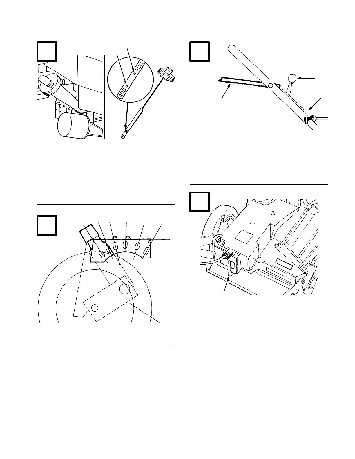
4. Insert dipstick into filler neck and rotate cap
clockwise 1/4 turn to lock.
Note: Check oil level each time mower is
used or after every 5 operating hours.
Initially, change oil after the first 5
hours of operation; thereafter, change
oil after every 50 hours of operation.
More frequent oil changes are required
in dusty or dirty conditions.
Fill Fuel Tank With Gasoline
POTENTIAL HAZARD
In certain conditions gasoline is extremely
flammable and highly explosive.
WHAT CAN HAPPEN
A fire or explosion from gasoline can burn
you, others, and cause property damage.
HOW TO AVOID THE HAZARD
Use a funnel and fill the fuel tank outdoors,
in an open area, when the engine is cold.
Wipe up any gasoline that spills.
Do not fill the fuel tank completely full.
Add gasoline to the fuel tank until the level
is 1/4” to 1/2” (6 mm to 13 mm) below the
bottom of the filler neck. This empty space
in the tank allows gasoline to expand.
Never smoke when handling gasoline, and
stay away from an open flame or where
gasoline fumes may be ignited by a spark.
Store gasoline in an approved container
and keep it out of the reach of children.
Never buy more than a 30-day supply of
gasoline.
This engine is certified to operate on unleaded
gasoline. Toro strongly recommends the use of fresh,
clean, UNLEADED regular grade gasoline with an
octane rating of 85 or higher in Toro gasoline
powered products. Unleaded gasoline burns cleaner,
extends engine life, and promotes good starting by
reducing the build-up of combustion chamber
deposits. In countries other than U.S.A., leaded
gasoline may be used if it is commercially available
and unleaded is unavailable.
IMPORTANT: Do not mix oil with the gasoline.
Do not use gasoline that has been stored in an
approved container from one season to the next.
Toro also recommends that Toro
Stabilizer/Conditioner be used regularly in all Toro
gasoline powered products during operation and
storage seasons. Toro Stabilizer/Conditioner cleans
the engine during operation and prevents gum–like
varnish deposits from forming in the engine during
periods of storage.
IMPORTANT: Some fuels, called oxygenated or
reformulated gasolines, are gasolines blended with
alcohols or ethers. Excessive amounts of these
blends can damage the fuel system or cause
performance problems. Never use methanol
,
gasoline containing methanol, gasohol containing
more than 10% ethanol or white gas because
engine fuel system damage could result. If any
undesirable operating symptoms occur, use
gasoline with a lower percentage of alcohol or
ether.
Do not use fuel additives other than those
manufactured for fuel stabilization during storage
such as Toro’s Stabilizer/Conditioner or a similar
product. Toro’s Stabilizer/Conditioner is a
petroleum distillate based conditioner/stabilizer.
Toro does not recommend stabilizers with an
alcohol base such as ethanol, methanol or
isopropyl. Additives should not be used to try to
enhance the power or performance of machine.
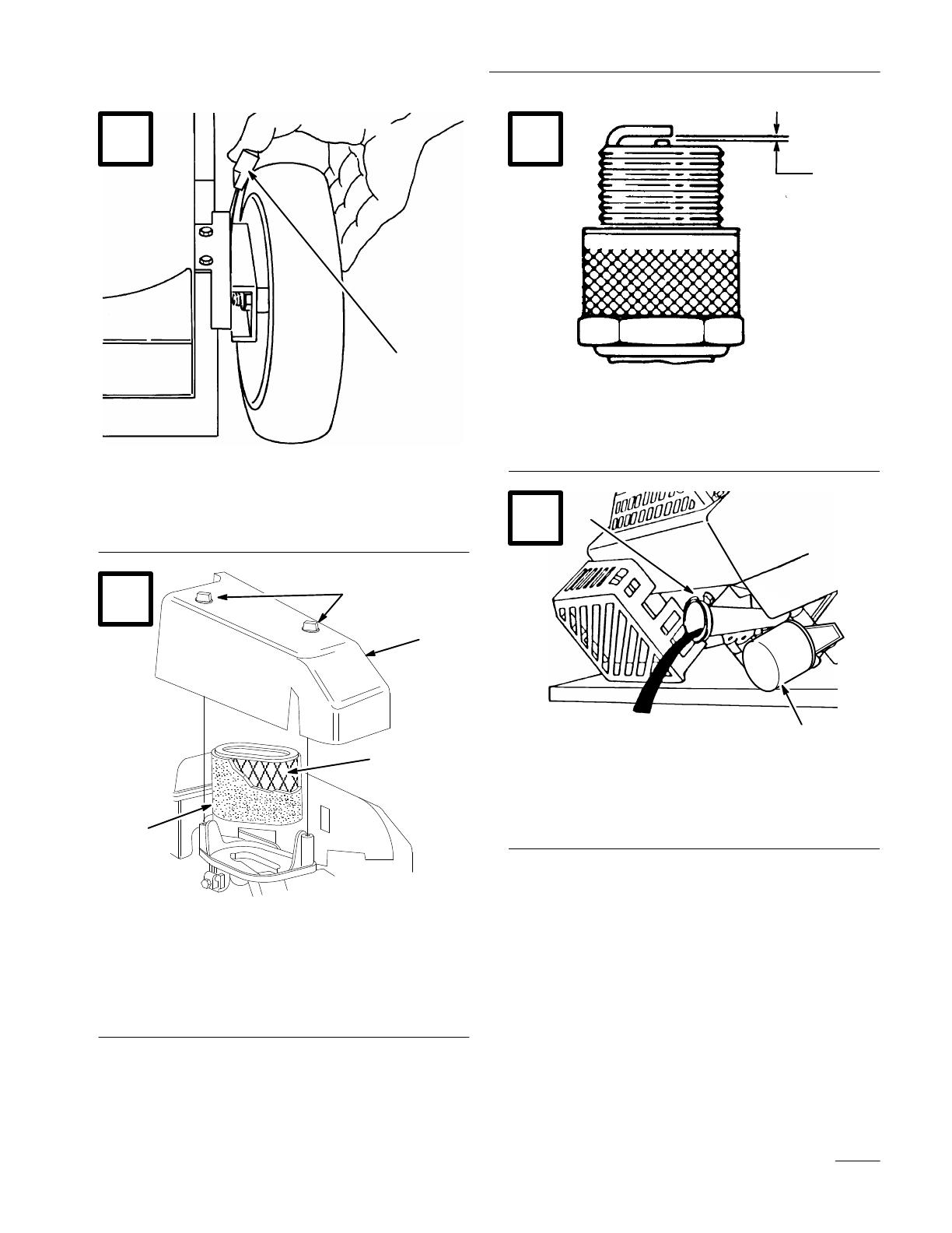
1. Clean around fuel tank cap and remove cap from
tank. Using unleaded gasoline, add fuel to 1/4”
to 1/2” (6 to 13 mm) from top of tank, not into
the filler neck. Do not fill the tank full.
2. Reinstall fuel tank cap and wipe up any spilled
gasoline.
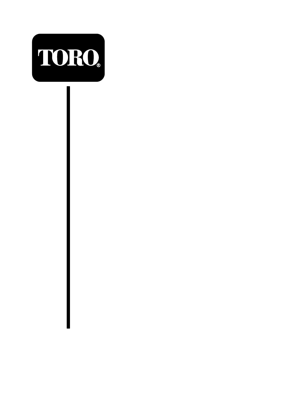
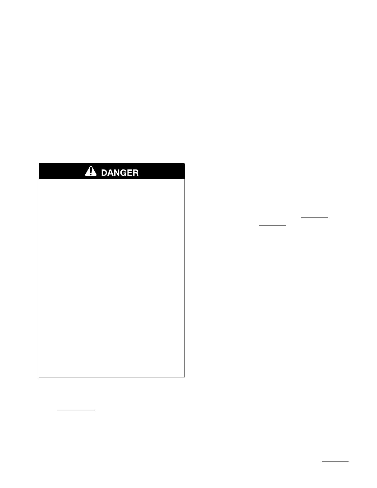
3. Connect spark plug wire (if disconnected)
(Fig. 12).
EN–7
Recycling Tips
General Tips
Follow these instructions whether cutting grass or
leaves for the best cutting results and lawn
appearance:
Maintain a sharp blade
throughout the cutting
season. Periodically file down nicks on blade.
Only mow dry grass or leaves. Wet grass and
leaves tend to clump on yard and may cause
mower to plug or engine to stall. They also may
be slippery to walk on and could cause you to
slip and fall.
POTENTIAL HAZARD
Wet grass or leaves can cause you to slip
and contact blade.
WHAT CAN HAPPEN
Blade contact can seriously injure you.
HOW TO AVOID THE HAZARD
Mow only in dry conditions.
Set engine speed to fastest position. Maximum
horsepower provides best cutting results.
Clean clippings or leaves from underside of
mower deck after each mowing.
Keep engine in good running condition. Cutting
and recutting requires more horsepower.
Clean air filter more frequently. Cutting and
recutting stirs up more clippings and dust which
clogs the air filter and reduces engine
performance.
Cutting Grass
Grass grows at different rates at different times
of the year. In the heat of the summer, it is
generally best to cut grass at the 1-#/4”, 2-!/4” or
2-#/4” height-of-cut settings (Fig. 9). Only about
!/3 of the grass blade should be cut off. Cutting
below the 1-#/4” setting is not recommended
unless grass is sparse or it is late fall when grass
growth begins to slow down.
When cutting grass over six inches tall, you may
want to first mow using the highest height-of-cut
setting and a slower walking speed; then mow
again at a lower setting for best lawn appearance.
If grass is too long and leaves clumps on top of
lawn, mower may plug and cause engine to stall.
Alternate mowing direction. This helps disperse
clippings over lawn for even fertilization.
If the finished cut lawn appearance is unsatisfactory,
try one or more of the following:
Sharpen the blade.
Walk at a slower pace while mowing.
Raise the height-of-cut setting on your mower.
Cut grass more frequently.
Overlap cutting swaths instead of cutting a full
swath with each pass.
Mow across the marginal areas a second time.
Set height-of-cut on front wheels one notch
lower than rear wheels. (example: set front
wheels at 1-#/4” setting and rear wheels at 2-!/4
setting)
Cutting Leaves
When cutting is complete, always be sure that
50% of the lawn shows through the cut leaf
cover. This may require one or more passes over
the leaves.
For light leaf coverage, position all wheels at the
same height-of-cut setting.
If there are more than five inches of leaves on
lawn, set the front wheels one or two notches
higher than the rear wheels. This makes it easier
to feed leaves under mower deck.
Walk at a slower mowing speed if leaves are not
being cut up finely enough to be hidden down in
the grass.
EN–8
If you cut up a lot of oak leaves, you might want
to add lime to your grass in the spring. Lime
reduces the acidity of oak leaves.
Operation
Operating Tips
1. CHECK OIL LEVEL—Maintain oil level
between ADD and FULL marks as shown on
dipstick (Fig. 8).
2. BEFORE EACH MOWING—Be sure blade
brake, self–propelled drive, and control bar
function properly. When control bar is released,
blade and self–propelled drive are designed to
stop. If controls are not functioning properly, do
not use mower until controls are repaired.
3. SHARP BLADE—Begin each cutting season
with a sharp blade. Periodically file down nicks.
Controls
Throttle control, blade/self–propelled control bar and
fingertip starter are on upper handle (Fig. 10). Ground
speed control is located at rear of belt cover (Fig. 11).
Starting, Stopping, And
Self–propelling
Note: The engine requires a warm-up period
of one minute to several minutes,
depending on the temperature.
1. Push spark plug wire onto spark plug (Fig. 12).
2. Move throttle control to
(FAST) position.
3. Move ground speed control to
(NEUTRAL).
4. Push primer three (3) times (Fig. 12). Wait
about two (2) seconds between each push.
Note: Do not use primer to restart a warm
engine after a short shutdown.
However, cool weather may require
priming to be repeated.
5. Pull recoil starter out until positive engagement
results; then pull vigorously to start the engine.
Allow the engine to warm-up. During warm-up,
the equipment can be operated. Regulate throttle
as desired when engine starts. Move ground
speed control to desired setting.
6. BLADE AND TRACTION OPERATION
(Fig. 13)—When control bar is in position “A”,
slide control bar to right and raise to position
“B” to engage blade. Squeeze control bar against
handle to position “C” to drive. To disengage
traction drive but keep blade engaged, gradually
release control bar to position “B”. To
self–propel with blade disengaged, simply
squeeze control bar against handle to position
“C”, without sliding control bar to right.
7. STOPPING—To stop engine, release control bar
and move throttle control to
(OFF). Pull wire
off spark plug if mower will be unattended or
not used.
Using Discharge Tunnel Plug
1. Make sure engine is off. Open the discharge door
by pulling forward on the handle and moving it
rearwards (Fig. 6). Hold the discharge door
handle to prevent the spring–loaded door from
closing while inserting the plug.
2. Since the plug is slightly wider than the
discharge tunnel opening, you must rotate the
plug clockwise slightly while inserting it
(Fig. 6). Make sure the arrow on the plug decal
is pointing upwards.
3. Push the plug all the way in until the spring clip
on the bottom of the plug clicks into place,
locking the plug securely into the discharge
tunnel (Fig. 7). Release the discharge door
handle to lock the top of the plug.
EN–9
4. To remove the plug, move the discharge door
handle rearwards while at the same time lift up
the spring clip on the bottom of the plug. When
the plug is unlocked, pull it out of the discharge
tunnel.
Note: When grass is thick and lush, clippings
may collect on and around the
discharge tunnel plug. This may make
plug removal difficult. Clean plug
thoroughly after each use. Refer to
Cleaning Mower, page 14.
Using Grass Bag
Occasionally you may wish to use the grass bag for
bagging extra long grass, lush grass or leaves.
1. Stop engine and wait for all moving parts to
stop.
2. Ensure discharge door handle is fully forward
and pin is engaged in catch (Fig. 14).
3. INSTALLING BAG—Slide hole in bag frame
onto retaining post on discharge tunnel (Fig. 14).
Set rear of bag frame onto lower handle.
POTENTIAL HAZARD
Grass clippings and other objects can be
thrown from an open discharge tunnel.
WHAT CAN HAPPEN
Objects thrown with enough force could
cause serious personal injury or death to
operator or bystander.
HOW TO AVOID THE HAZARD
Never open door on discharge tunnel when
engine is running unless the grass bag,
optional side discharge attachment or
discharge tunnel plug is securely installed.
4. Pull discharge door handle forward until pin
clears catch and move handle rearward until pin
locks in bag notch (Fig. 15). Discharge door in
mower housing is now open.
POTENTIAL HAZARD
A worn grass bag could allow small stones
and other similar debris to be thrown in
operator’s or bystander’s direction.
WHAT CAN HAPPEN
Thrown objects can cause serious personal
injury or death to operator or bystanders.
HOW TO AVOID THE HAZARD
Check the grass bag frequently. If it is
damaged, install a new genuine TORO
replacement bag.
POTENTIAL HAZARD
Thrown objects may result if discharge
door does not close completely.
WHAT CAN HAPPEN
Thrown objects can cause serious
personal injury or death.
HOW TO AVOID THE HAZARD
If discharge door cannot be closed because
grass clippings clog discharge area, stop
engine and gently move discharge door
handle back and forth until door can be
closed completely. If door still cannot be
closed, remove obstruction with a stick, not
your hand.
5. EMPTYING BAG—Stop engine and wait for all
moving parts to stop. Raise discharge door
handle and move it forward to engage the
locking pin with the catch (Fig. 14). Grasp
handles at front and rear of bag and lift bag off
mower. Gradually tip bag forward to empty
clippings.
  • Page 1 1
  • Page 2 2
  • Page 3 3
  • Page 4 4
  • Page 5 5
  • Page 6 6
  • Page 7 7
  • Page 8 8
  • Page 9 9
  • Page 10 10
  • Page 11 11
  • Page 12 12
  • Page 13 13
  • Page 14 14
  • Page 15 15
  • Page 16 16
  • Page 17 17
  • Page 18 18
  • Page 19 19
  • Page 20 20
  • Page 21 21
  • Page 22 22
  • Page 23 23
  • Page 24 24
  • Page 25 25
  • Page 26 26
  • Page 27 27
  • Page 28 28
  • Page 29 29
  • Page 30 30
  • Page 31 31
  • Page 32 32
  • Page 33 33
  • Page 34 34
  • Page 35 35
  • Page 36 36
  • Page 37 37
  • Page 38 38
  • Page 39 39
  • Page 40 40
  • Page 41 41
  • Page 42 42
  • Page 43 43
  • Page 44 44
  • Page 45 45
  • Page 46 46
  • Page 47 47
  • Page 48 48
  • Page 49 49
  • Page 50 50
  • Page 51 51
  • Page 52 52
  • Page 53 53
  • Page 54 54
  • Page 55 55
  • Page 56 56
  • Page 57 57
  • Page 58 58
  • Page 59 59
  • Page 60 60

Toro 22162 User manual

Category
Lawnmowers
Type
User manual
This manual is also suitable for

Ask a question and I''ll find the answer in the document

Finding information in a document is now easier with AI

in other languages