Page is loading ...

Operating instructions
Last updated: 04.2016
Motor unit for hinged gates
Comfort 585, 586
GB

2 Operating instructions, Comfort 585, 586 (#102836 – GB)
Table of Contents
1. General safety instructions .....................3
1.1 Intended use ................................3
1.2 Target group ................................3
1.3 Warranty ...................................3
2. Scope of supply ..............................4
3. Gate system .................................4
4. Installation ..................................5
4.1 Preparing for installation .......................5
4.2 Foundation layout ............................6
4.3 Installing the operator housing. . . . . . . . . . . . . . . . . . . 6
4.4 Installing the gate wing ........................8
4.5 Installing the motor unit .......................9
4.6 Installing the release mechanism .................9
4.7 Fitting the limit stops .........................10
4.8 Fitting the reference point sensor ................10
4.9 Setting the limit stops ........................10
4.10 Completing the installation ....................11
4.11 Connecting to the junction box .................11
4.12 Connection to the control unit ..................12
5. Operation ..................................12
5.1 Hand transmitter ............................12
5.2 Release mechanism ..........................12
6. Care and cleaning ............................12
7. Maintenance ...............................13
7.1 Maintenance work by the operator. . . . . . . . . . . . . . . 13
7.2 Maintenanceworkbyqualiedandtrained
professionals ...............................13
8. Disassembly ................................13
9. Disposal ...................................13
10. Rectifying faults .............................13
11. Appendix ..................................14
11.1 Technical data ..............................14
11.2 Declaration for the incorporation of a partly
completed machine ..........................15
Regarding this document
– Original instruction manual.
– Part of the product.
– Read these instructions carefully before use and keep them in a
safe place for future reference.
– Protected by copyright.
– No part of this manual may be reproduced without our prior
approval.
– Subject to alterations in the interest of technical progress.
– All dimensions are given in millimetres.
– The drawings are not true to scale.
Meaning of symbols
DANGER!
Safety notice indicating a danger that will directly result in death or
severe injury.
WARNING!
Safety notice indicating a danger that could result in death or severe
injury.
CAUTION!
Safety notice indicating a danger that could result in slight or
moderate injuries.
NOTICE
Safety notice indicating a danger that could result in damage to
property or irreparable damage to the product.
CHECK
Reference to a check that needs to be carried out.
REFERENCE
Reference to separate documents that must be observed.
• Instruction requiring action
– List, itemisation
➔ Reference to other sections of this document
) Factory settings
DANGER!
IMPORTANT SAFETY INSTRUCTIONS:
ATTENTION! IT IS VITALLY IMPORTANT FOR THE SAFETY OF
PERSONS THAT YOU FOLLOW ALL THE INSTRUCTIONS.
KEEP THESE INSTRUCTIONS IN A SAFE PLACE.
IMPORTANT INSTRUCTIONS FOR SAFE INSTALLATION:
ATTENTION! SERIOUS INJURIES CAN BE CAUSED IF THE EQUIPMENT
IS NOT INSTALLED CORRECTLY – BE SURE TO FOLLOW ALL THE
INSTALLATION INSTRUCTIONS.

Operating instructions, Comfort 585, 586 (#102836 – GB) 3
1. General safety instructions
DANGER!
Failure to comply with the documentation could result in
life-threatening danger!
• Be sure to follow all the safety instructions in this document.
1.1 Intended use
– The operator system is designed exclusively for opening and closing
gates.
– Never use the gate to lift persons or objects.
The following applies for the product Comfort 585, 586:
– The following data must be complied with:
– Maximum pulling force
– Maximum compressive force
– Maximum gate size
– Maximum gate weight
➔ “11.1 Technical data”
– This product is intended for residential use.
– This product is only suitable for hinged gates.
– The motor unit requires a suitable control unit for operation.
1.2 Target group
– Installation, connection, setting in operation and servicing:
Qualied,trainedskilledpersonnel.
– Operation, inspection and servicing:
The operator of the gate system.
Requirementstobemetbyqualiedandtrainedskilledpersonnel:
– Knowledgeofthegeneralandspecicsafetyandaccident
prevention regulations.
– Knowledge of the relevant electrical regulations.
– Training in the use and care of appropriate safety equipment.
– Adequateinstructionandsupervisionbyqualiedelectricians.
– The ability to recognise hazards that can be caused by electricity.
– Knowledge of the application of the following standards
– EN 12635 (“Doors and gates - Installation and use”),
EN 12453 (“Safety in use of power operated doors -
Requirements”),
– EN 12445 (“Safety in use of power operated doors -
Test methods”),
– EN 13241-1 (“Industrial, commercial and garage doors and
gates-Part1:Productswithoutreresistanceorsmokecontrol
characteristics”)
Requirements to be met by the operator of the gate system:
– Knowledge and safekeeping of the instruction manual.
– Safe and proper keeping of the inspection logbook.
– Knowledge of general safety and accident-prevention regulations.
– Instruction of all persons who use the door system.
– Ensure that the door system is serviced and maintained periodically
byqualiedandtrainedprofessionals.
Special requirements apply to the following users:
– Children aged eight and above.
– Persons with with reduced physical, sensory or mental capabilities.
– Persons with a lack of experience and knowledge.
These users are only authorised to operate the device.
Special requirements:
– The users must be supervised.
– The users must have been briefed on how to use the device.
– The users must understand the dangers involved in handling the
device.
– Children are not allowed to play with the device.
1.3 Warranty
The product is manufactured in accordance with the directives
and standards listed in the manufacturer’s declaration and in the
declaration of conformity.
The product left the factory in perfect working order.
In the following cases, the manufacturer will accept no liability for
damage. The warranty for the product and accessory components
becomes void in the event of:
– Failure to observe these operating instructions.
– Incorrect handling and use of the product for anything other than
its intended purpose.
– Workbeingcarriedoutbyunqualiedpersonnel.
– Changesormodicationstotheproduct.
– The use of replacement parts that have not been approved or were
not manufactured by the manufacturer.
The warranty does not cover batteries, rechargeable batteries, fuses and
bulbs.
Further safety instructions are given in the relevant sections
of this document.
➔ “4. Installation”
➔ “6. Care and cleaning”
➔ “8. Disassembly”

4 Operating instructions, Comfort 585, 586 (#102836 – GB)
2. Scope of supply
The Comfort 586 / 586 can be supplied in the following versions, as
required:
Single wing gate system:
– Comfort 585 / 586, 1x motor unit
Double wing gate system:
– Comfort 585 / 586, 2x motor unit
The supply package includes
– Operator housing
– Housing cover
– Electric motor
– Crankset
– Wing device
– Connecting rod
– Adjustable limit stop in CLOSING direction
– Adjustable limit stop in OPEN direction
– Fixing materials for cover and limit stops
– Grease, type A (water-repellent)
– Emergency release mechanism
– Junction box with terminal strip
The scope of supply is doubled in the case of double wing gate
versions.
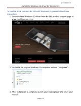
Overview of components
2 / 1
1
2
3
4
5
6
7
8
11
10
9
Comfort 585 / 586 (assembled, without housing cover)
1 Crankset
2 Electric motor
3 Coverxingscrews
4 Wing device
5 Connecting rod
6 Operator housing
7 Water drain hole
8 Cable opening
9 Support plate for reference point sensor
10 Adjustable limit stop in CLOSING direction
11 Adjustable limit stop in OPEN direction
3. Gate system
3 / 1
a
1
1
4
7
8
10
2
2
3
6
5
9
a
a
c
c
a
a
c
b
b
11
11
This is just an example of a gate system and can vary depending on
the type of gate and the associated equipment. The gate system shown
comprises the following components:
1 Photocell
2 Photocell
3 Signal light
4 Key switch post (for code button, transponder, ...)
5 Wrench
6 Main switch (mains isolator switch)
7 Electric lock
8 Ground stop
9 Mains cable
10 Closing edge safety device (CESD)
11 Junction box with terminal strip
Cable cross-sections:
a 2 x 0.5 mm
2
b 6 x 0.75 mm
2
c 3 x 1.5 mm
2
d 2 x 0.75 mm
2
REFERENCE
For the installation and cabling of the gate sensors, control elements
and safety equipment, the relevant installation instructions must be
observed.

Operating instructions, Comfort 585, 586 (#102836 – GB) 5
4. Installation
DANGER!
Life-threatening danger due to electric shock!
• It is vital that you disconnect the operator system from the
power supply before commencing cabling work. Take measures
to ensure that the power supply remains disconnected for the
duration of the cabling work.
• Observe the local safety regulations.
• It is imperative that you lay power cables separately from control
cables.
The control voltage is 24V DC.
NOTICE
Material damage resulting from incorrect installation of the
operator!
To avoid installation errors and damage to the gate and operator
system, the following installation instructions must be observed at all
costs.
• Ensure that the gate is in good mechanical order:
– The gate can be moved easily.
– The gate opens and closes properly.
• Onlyusexingmaterialsthataresuitableforthefoundation
material in question.
4.1 Preparing for installation
Before commencing installation, the following works must be carried
out without fail.
Foundations
• Check the proposed position of the foundation.
Scope of supply
• Check that all the parts are present.
• Check that all the necessary accessory parts for your installation
situation are present.
Gate system
• Ensurethatyourgatesystemstructureissufcientlystabletoallow
for automation.
• Ensure that the gate can be easily moved by hand.
• Ensure that there are no obstructions in the path of movement of
the gate.
• Disassemble the gate latches or render them inoperable.
• Makesurethatthesizeofthetopgatehingeissufcientlylargefor
automatic gate operation.
• Remove all other hinges.
• Ensure that a suitable mains connection and a mains isolator
switch are available for your gate system.
Theminimumcross-sectionoftheearthcablemustbe3x1.5mm
2
.
• Ensure that all cables are suitable for outdoor use with respect to
UV resistance and cold resistance.
• Ensure that a suitable control unit is available for your gate system.
• In double wing gate systems, ensure that a cable connection is
available from the second motor unit to the control.
The minimum cross-section of this cable must be 6 x 0.75 mm
2
.
• Observe the following gate requirements:
➔ “11.1 Technical data”
The use of a mechanical ground stop in the CLOSED gate position is
recommended if the gate wing measures 1.8 metres or more.
For gate wing widths of 2 metres or more, the use of an electric lock is
recommended.
REFERENCE
When using and installing accessory equipment, observe the
corresponding documentation.

6 Operating instructions, Comfort 585, 586 (#102836 – GB)
4.2 Foundation layout
NOTICE
Material damage resulting from incorrect installation of the
operator!
• Ensure that the size of the foundation is adhered to and that a
suitable recess is prepared.
• Make sure there is a minimum distance of 47 mm between the
axis of rotation and the post.
• EnsurethataPVCwaterdrainagepipe(E)(atleastø40mm)
is connected to opening (A) on the operator housing and to the
drainage system.
• Make sure that an empty conduit (at least ø 30 mm) for electrical
cabling is connected to opening (B) on the operator housing and
to the corresponding junction box (C).
• Ensure that the operator housing is inserted in the centre of the
foundation.
• Check to ensure that the distance between the housing cover and
the lower edge of the gate is 64 mm.
• Ensure that the foundation extends below the frost depth
(>800mm).
4.2 / 1
640
450
>800
200
4.2 / 2
> 47 mm
AB
4.2 / 3
C
D
E
4.2 / 4
64 mm
4.3 Installing the operator housing
4.3 / 1
• Place the operator housing in the prepared opening.

Operating instructions, Comfort 585, 586 (#102836 – GB) 7
4.3 / 4
G
• Lubricate the crankset (G) with grease (type A).
• Attach the crankset to the hollow shaft.
4.3 / 5
H
I
• Lubricate the drill-hole (H) with grease (type A).
• Lubricate the wing device (I) with grease (type A).
• Insert the wing device into the drill-hole (H).
4.3 / 2
F
• Align the operator housing so that it is perpendicular to the axis of
rotation (F) of the gate hinge.
• Observethespeciedinstallationconditions.
• Check to ensure that the distance between the housing cover and
the lower edge of the gate is 64 mm.
➔ “4.2 / 4”
• Use self-adhesive tape to seal any holes in the operator housing
that are not required.
• Close the operator housing with the cover plate.
• Seal the cover plate using self-adhesive tape.
• Fill in the space surrounding the operator housing with concrete.
NOTICE
Material damage resulting from incorrect installation of the
operator!
• Ensure that the operator housing does not change its position
during the concreting work.
• Check that the operator housing is horizontal.
• Allow the foundation concrete to fully set.
• Remove the self-adhesive tape and the cover plate.
4.3 / 3
• Lubricate the opening of the hollow shaft and the ball with grease
(type A).
• Place the ball in the hollow shaft.

8 Operating instructions, Comfort 585, 586 (#102836 – GB)
4.3 / 6
A
B
A
J
G
B
G
• Place the limit stop cams in the crankset (G).
• Attach the limit stop cams with the appropriate bolts.
• Lubricate the wing device through the lubricating nipple (J) until
grease escapes on both sides
(grease DIN 51502 KP 2 N - K 2 K-20, not included in the scope of
supply).
4.4 Installing the gate wing
CHECK
• Check that the foundation is fully set.
4.4 / 1
• Ensure that the axis of rotation of the gate hinge is aligned with
the pivot point of the wing device.
• Check to ensure that the distance between the housing cover and
the lower edge of the gate is 64 mm.
➔ “4.2 / 4”
4.4 / 2
F
• Position the gate wing on the wing device.
• Pay particular attention to the axis of rotation (F) of the gate wing
hinge.
NOTICE
Material damage due to welding!
• Weld the contact surface with 3-4 cm long welding seams.
• Do not weld in the vicinity of drill-holes.

Operating instructions, Comfort 585, 586 (#102836 – GB) 9
4.4 / 3
• Weld the wing device to the gate wing.
4.5 Installing the motor unit
4.5 / 1
A
B
• Allocate the motors to the gate sides so that the motors are facing
the direction of opening.
4.5 / 2
A
B
• Place the operator in the operator housing.
• Attach the operator inside the operator housing.
4.5 / 3
L
K
K
• Lubricate the drill-holes (K) for the connecting rod (L) with grease
(type A).
• Connect the crankset and the motor with the connecting rod (L).
4.6 Installing the release mechanism
4.6 / 1
M
• Lubricate the dowel pin (M) with grease (type A).
• Attach the release mechanism under the wing device.

10 Operating instructions, Comfort 585, 586 (#102836 – GB)
4.7 Fitting the limit stops
• Close the wing of the gate.
4.7 / 1
N
O
• Fit the limit stop cam (N).
4.8 Fitting the reference point sensor
4.8 / 1
P
• Attach the reference point sensor (P) so that the rotatable arm
moves over the reference point sensor every time that the gate
moves.
4.9 Setting the limit stops
4.9.1 Setting the CLOSED gate position
4.9.1 / 1
+
-
+
-
+
-
+
-
• Setthelimitstopwiththeaidofthethexingscrews(O).
The limit stop can be adjusted between an angle of 85° - 95° in the
CLOSED gate setting.
+ Gate closes further
- Gate does not close as far
4.9.2 Setting the OPEN gate position
If the gate system has a gate stop in the OPEN direction, the OPEN
travel limit stop does not need to be set.
• Close the wing of the gate.
4.9.2 / 1
± 10°
1
2
• Open the gate wing to its full extent (1).
• Close the gate wing approx. 10° (2).

Operating instructions, Comfort 585, 586 (#102836 – GB) 11
4.11 Connecting to the junction box
NOTICE
Incorrect storage or installation of the junction box can
cause damage!
The operator housing is designed to permit water to ingress into
the housing. If the junction box is stored in the operator housing,
the electrical connections in the junction box may therefore become
corroded.
• Make sure that the junction box is not stored inside the operator
housing.
4.11 / 1
• Install the junction box at least 100 mm above the roadway.
• Thread the connection cables from the motor unit through the
cable gland and into the junction box housing.
• Attach the connection cables as required.
➔ “4.12 / 1”
4.9.2 / 2
Q
R
S
• Loosen screws (Q) and (R).
• Rotate the cam (S) as far as it will go with the aid of the connecting
rod.
• Tighten screws (Q) and (R).
The gate wing opening can be adjusted by setting the cam (Q).
4.10 Completing the installation
• Close the operator housing with the cover plate.
• Screw down the cover plate.
CHECK
To ensure that installation is correct, the following tests must be
carried out:
• Release the operator.
➔ “5.2 Release mechanism”
• Move the gate slowly by hand into the OPEN and CLOSED end
positions.
4.10 / 1
J
• Lubricate the wing device through the lubricating nipple (J) until
grease escapes on both sides
(grease DIN 51502 KP 2 N - K 2 K-20).

12 Operating instructions, Comfort 585, 586 (#102836 – GB)
4.12 Connection to the control unit
To operate the motor unit, the junction box must be connected to a
suitable control unit (not included in the scope of supply).
REFERENCE
Follow the instructions in the relevant documentation when
connecting the operator to the control unit.
4.12 / 1 M12E030 b
- A2
- XM70A/B
- A1
- W1
BN
WH BK BU
- X1
1 2 3 4 5 6
GN
GN
BN
BN
WH
WH
BU
BN
VT RD
A1
A2
V5
11
15
10
BK
- X4
- X5
A1
Junction box housing
➔ “4.11 Connecting to the junction box”
A2 Control unit: Control x.52
M1 Motor unit
X4 RPM sensor
X5 Reference point sensor
To change the rotational direction of the motor, connections A1 and A2
on terminal -XM70A/B in the control unit must be swapped.
REFERENCE
Follow the instructions in the relevant documentation when
connecting to the control unit.
5. Operation
5.1 Hand transmitter
REFERENCE
Follow the instructions in the relevant documentation for operation
with a hand transmitter.
5.2 Release mechanism
REFERENCE
The procedure for releasing the operator is described in the documen-
tation provided with it.
6. Care and cleaning
DANGER!
Life-threatening danger due to electric shock!
• It is vital that you disconnect the operator system from the
power supply before commencing cleaning work. Take measures
to ensure that the power supply remains disconnected for the
duration of the cleaning work.
NOTICE
Damage to property due to incorrect handling!
When cleaning the operator system, never use:
direct water jets, high pressure cleaners, acids or alkaline solutions.
• Clean the outside of the housing with a soft, damp, lint-free cloth.
If heavily soiled, the housing can be cleaned with a mild detergent.

Operating instructions, Comfort 585, 586 (#102836 – GB) 13
9. Disposal
Do not dispose of old equipment or batteries with the
normal household waste!
• Dispose of old devices at a waste collection centre for electronic
waste or via a specialist dealer.
• Dispose of old batteries in a battery recycling container or via a
specialist dealer.
• Dispose of the packaging material in the special waste collection
containers for paper, cardboard and plastic.
10. Rectifying faults
REFERENCE
To rectify faults, follow the instructions in the control unit
documentation.
7. Maintenance
7.1 Maintenance work by the operator
Damageorweartoadoorsystemmustonlyberectiedbyqualied
and trained professionals.
To ensure fault-free operation, the gate system must be inspected
regularly and, if necessary, be repaired. Before starting work on the
gate system, the operator system must always be disconnected from
the power supply.
• Check once a month that the operator system reverses when the
gate touches an obstacle. Place an obstacle in the path of the gate
to check this.
• Check all the moving parts of the gate system and gate operator
system.
• Check the gate system for signs of damage or wear and tear.
• Move the gate manually to check that the gate travels easily and
smoothly.
• Check that the photocell functions properly.
• Check that the closing edge safety device functions properly.
• Check the power supply cable for signs of damage.
For safety reasons, if the power supply cable is damaged it must be
replaced by the manufacturer or his customer service department,
orbyasimilarlyqualiedperson.
7.2 Maintenance work by qualied and trained
professionals
Power-operated windows, doors and gates must be inspected by
qualiedandtrainedprofessionalswhenevernecessary,butatleast
once a year (written inspection records must be kept).
• Test the driving power with a force tester designed for this purpose.
• Replace any damaged or worn parts.
8. Disassembly
DANGER!
Life-threatening danger due to electric shock!
• It is vital that you disconnect the operator system from the
power supply before commencing dismantling work. Take
measures to ensure that the power supply remains disconnected
for the duration of the dismantling work.
WARNING!
Possibility of serious injury due to incorrect dismantling!
• Comply with all applicable occupational health and safety
regulations.
Thesystemmustbedismantledbyqualiedandtrainedprofessionals,
following the installation instructions in reverse order.

14 Operating instructions, Comfort 585, 586 (#102836 – GB)
11. Appendix
11.1 Technical data
Electrical data
Duty cycle min. short-term 5
Control voltage V DC 24
Protection category of motor unit IP 67
Protection class II
Mechanical data
Max. torque Nm
Comfort 585: 250
Comfort 586: 300
Travel speed mm/s 15-20
Opening time, dependent on gate
type
s 18
Environmental data
Dimensions of motor unit
322
64
47
175
410
Weight kg
Comfort 585: 12.0
Comfort 586: 12.5
Weight (double wing gate) kg
Comfort 585: 24.0
Comfort 586: 25.0
Sound pressure level dB(A) < 70
Temperature range
°C -20
°C +55
* without any additional equipment connected
Use Comfort
585 586
Hinged gates
– Max. gate wing width
– Max. gate wing weight
for gate width up to 1.0 m
for gate width up to 2.0 m
for gate width up to 2.5 m
for gate width up to 3.0 m
– Opening angle
– Gate incline
mm
kg
kg
kg
kg
° max.
% max.
2,500
250
150
100
–
110
0
3,000
600
400
250
150
110
0
Force diagram
Comfort 585 Comfort 586
0
0
150
300
450
600
0,5 1,0 1,5 2,0 2,5 3,0
m
kg

Operating instructions, Comfort 585, 586 (#102836 – GB) 15
Authorised agent for the preparation of the technical documentation:
Marantec Antriebs- und Steuerungstechnik GmbH & Co. KG,
Remser Brook 11 · 33428 Marienfeld · Germany
Fon +49 (5247) 705-0
Marienfeld, 1 February 2016 M. Hörmann
Director
11.2 Declaration for the incorporation of a partly
completed machine
(Declaration of Incorporation in line with EC Machinery Directive
2006/42/EC in accordance with Annex II, Part 1 B)
Manufacturer:
Marantec Antriebs und Steuerungstechnik GmbH & Co. KG
Remser Brook 11, 33428 Marienfeld, Germany
The partly completed machine (product):
Hinged-gate opener Comfort 585, 586
Revision status: R01
has been developed, designed and manufactured in accordance with
the:
– EU Machinery Directive 2006/42/EC
– EU RoHS Directive 2011/65/EU
– EU Low Voltage Directive 2014/35/EU
– EU Electromagnetic Compatibility Directive 2014/30/EU
– Radio Equipment Directive (RED) 2014/53/EU
Appliedandreferencedstandardsandspecications:
– EN ISO 13849-1, PL “c”, Cat. 2
Safety of machinery - Safety-related parts of control systems -
Part 1: General principles for design
– EN 60335-2-103
Household and similar electrical appliances – Safety – Part 2-103:
Particular requirements for drives for gates, doors and windows.
– EN 61000-6-3/2
Electromagnetic compatibility – Emitted interference and immunity
The following requirements of EC Directive 2006/42/EC were complied
with:
General principles, No. 1.1.2, 1.1.3, 1.1.5, 1.1.6, 1.2.1, 1.2.2, 1.2.3,
1.2.6, 1.3.1, 1.3.4, 1.3.7, 1.3.8, 1.3.9, 1.4.1, 1.4.3, 1.5.1, 1.5.4, 1.5.6,
1.5.8, 1.5.14, 1.7
Furthermore, we declare that the special technical documentation for
this partly completed machine was prepared in accordance with Annex
VII Part B and we undertake to supply these documents, in electro-
nic form, to the national authorities in response to a duly reasoned
request.
This partly completed machine is intended only for installation in a door
system, in order to create a complete machine pursuant to Machinery
Directive 2006/42/EC. The door system may not be set in operation
until it has been ascertained that the complete system complies with
the requirements of the above-mentioned EC directives.
This declaration shall no longer be valid if changes are made to the
product without our authorisation.

1 - GB 360372 - M - 0.5 - 0712
102836
Identication plate, motor unit 1
Type A ___________________________________________________________________________________________
Rev (B) ___________________________________________________________________________________________
Art. no. (C) ___________________________________________________________________________________________
Prod. no. (GB) ___________________________________________________________________________________________
Identication plate, motor unit 2 (only double wing)
Type A ___________________________________________________________________________________________
Rev (B) ___________________________________________________________________________________________
Art. no. (C) ___________________________________________________________________________________________
Prod. no. (GB) ___________________________________________________________________________________________
Remser Brook 11
DE - 33428 Marienfeld
MADE IN GERMANY
A
BC
D
/
/