
®
K.2 Series
K.2 Series
K.2 Series
K.2 Series
User Manual
K8.2 – 105° 2000 W active 8” (200 mm) 2-way loudspeaker system
K10.2 – 90° 2000 W active 10” (250 mm) 2-way loudspeaker system
K12.2 – 75° 2000 W active 12” (300 mm) 2-way loudspeaker system
TD-000523-01-E
*TD-000523-01*

2
TD-000523-01-E
EXPLANATION OF SYMBOLS
The term “WARNING!” indicates instructions regarding personal safety. If the instructions are not followed the result may
be bodily injury or death.
The term “CAUTION!” indicates instructions regarding possible damage to physical equipment. If these instructions are
not followed, it may result in damage to the equipment that may not be covered under the warranty.
The term “IMPORTANT!” indicates instructions or information that are vital to the successful completion of theprocedure.
The term “NOTE” is used to indicate additional useful information.
NOTE: The intent of the lightning flash with arrowhead symbol in a triangle is to alert the user to the presence
of un-insulated “dangerous” voltage within the product’s enclosure that may be of sufficient magnitude to
constitute a risk of electric shock to humans.
NOTE: The intent of the exclamation point within an equilateral triangle is to alert the user to the presence of
important safety, and operating and maintenance instructions in this manual.
IMPORTANT SAFETY INSTRUCTIONS
WARNING!: TO PREVENT FIRE OR ELECTRIC SHOCK, DO NOT EXPOSE THIS EQUIPMENT TO RAIN OR
MOISTURE. DO NOT USE THIS APPARATUS NEAR WATER.
1. Read these instructions.
2. Keep these instructions.
3. Heed all warnings.
4. Follow all instructions.
5. Do not use this apparatus near water.
6. Clean only with a dry cloth.
7. Do not block any ventilation opening. Install in accordance with the manufacturer’s instructions.
8. Do not install near any heat sources such as radiators, heat registers, stoves, or other apparatus (including amplifiers)
that produce heat.
9. Do not defeat the safety purpose of the polarized or grounding-type plug. A polarized plug has two blades with one
wider than the other. A grounding type plug has two blades and a third grounding prong. The wide blade or the
third prong are provided for your safety. If the provided plug does not fit into your outlet, consult an electrician for
replacement of the obsolete outlet.
10. Protect the power cord from being walked on or pinched particularly at plugs, convenience receptacles, and the point
where they exit from theapparatus.
11. Only use attachments/accessories specified by the manufacturer.
12. Unplug this apparatus during lightning storms or when unused for long periods of time.
13. Refer all servicing to qualified service personnel. Servicing is required when the apparatus has been damaged in any
way, such as power-supply cord or plug is damaged, liquid has been spilled or objects have fallen into the apparatus,
the apparatus has been exposed to rain or moisture, does not operate normally, or has been dropped.

3
TD-000523-01-E
14. The appliance coupler, or the AC Mains plug, is the AC mains disconnect device and shall remain readily operable
after installation.
15. Adhere to all applicable, local codes.
16. To prevent electrical shock, the power cord shall be connected to a mains socket outlet with a protective earthing connection.
17. Consult a licensed, professional engineer when any doubt or questions arise regarding a physical equipment installation.
18. Do not use any aerosol spray, cleaner, disinfectant or fumigant on, near or into the apparatus. Clean only with a dry cloth.
19. Do not unplug the unit by pulling on the cord, use the plug.
20. Do not submerge the apparatus in water or liquids.
21. Keep ventilation opening free of dust or other matter.
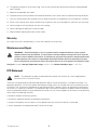
Warranty
For a copy of the QSC Limited Warranty, visit the QSC website at www.qsc.com
Maintenance and Repair
WARNING!: Advanced technology, e.g., the use of modern materials and powerful electronics, requires specially
adapted maintenance and repair methods. To avoid a danger of subsequent damage to the apparatus, injuries to persons
and/or the creation of additional safety hazards, all maintenance or repair work on the apparatus should be performed only
by a QSC authorized service station or an authorized QSC International Distributor. QSC is not responsible for any injury,
harm or related damages arising from any failure of the customer, owner or user of the apparatus to facilitate those repairs.
Life Cycle: 10 years, Storage Temperature range: -20C to +70C, Relative Humidity range: 5 - 85% RH
FCC Statement
NOTE: This equipment has been tested and found to comply with the limits for a Class B digital device,
pursuant to Part 15 of the FCC Rules.
These limits are designed to provide reasonable protection against harmful interference in a residential installation. This
equipment generates, uses and can radiate radio frequency energy and, if not installed and used in accordance with the
instructions, may cause harmful interference to radio communications. However, there is no guarantee that interference
will not occur in a particular installation. If this equipment does cause harmful interference to radio or television reception,
which can be determined by turning the equipment off and on, the user is encouraged to try to correct the interference by
one or more of the following measures:
• Reorient or relocate the receiving antenna.
• Increase the separation between the equipment and receiver.
• Connect the equipment into an outlet on a circuit different from that to which the receiver is connected.
• Consult the dealer or an experienced radio/TV technician for help.

4
TD-000523-01-E
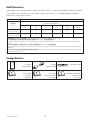
RoHS Statements
These products are in compliance with European Directive 2011/65/EU – Restriction of Hazardous Substances (RoHS).
These products are in compliance with “China RoHS” directives per GB/T26572. The following table is provided for
product use in China and its territories:
These products 这些产品
部件名称
(Part Name)
有害物质
(Hazardous Substances)
铅
(Pb)
汞
(Hg)
镉
(Cd)
六价铬
(Cr(vi))
多溴联苯
(PBB)
多溴二苯醚
(PBDE)
电路板组件
(PCB Assemblies)
X O O O O O
机壳装配件
(Chassis Assemblies)
X O O O O O
本表格依据 SJ/T 11364 的规定编制。(This table is prepared following the requirement of SJ/T 11364.)
O: 表示该有害物质在该部件所有均质材料中的含量均在 GB/T 26572 规定的限量要求以下。
O: Indicates that the concentration of the substance in all homogeneous materials of the part is below the relevant threshold specified in GB/T
26572.
X: 表示该有害物质至少在该部件的某一均质材料中的含量超出 GB/T 26572 规定的限量要求。
X: Indicates that the concentration of the substance in at least one of all homogeneous materials of the part is above the relevant threshold specified in
GB/T 26572.
(目前由于技术或经济的原因暂时无法实现替代或减量化) (Replacement and reduction of content cannot be achieved currently because of the
technical or economic reason.)
Package Contents
1
K.2 Series
Loudspeaker
1
Locking
AC Power cord
1
White QSC Logo
1
QSC Limited
Warranty
TD-000453
1
K.2 Series
Quick Start Guide
TD-000452
1
Powered Loudspeaker
Safety Sheet
TD-000337
K.2 Series

5
TD-000523-01-E
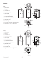
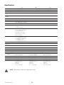
Features
K8.2
1. ABS enclosure
2. Steel grille
3. Front power LED
4. Cast aluminum handle
5. Power module
6. M10 installation points
7. M8 yoke-attachment points
8. 7.5° Downward-tilt pole socket
9. Vertical pole socket
10. Pull-back ring
11. Slip-resistant feet for floor monitor applications
12. Angled back for use as a stage monitor
K10.2
1. ABS enclosure
2. Steel grille
3. Front power LED
4. Cast aluminum handles
5. Power module
6. M10 installation points
7. M8 yoke attachment points
8. 7.5° Downward-tilt pole socket
9. Vertical pole socket
10. Pull-back ring
11. Slip-resistant feet
12. Angled back for use as a stage monitor
— Figure 1 —
K.2 Series
1
4
7
5
6
7
9
8
3
1
7
4
10
10
11
11
6
1111
12
11
2
— Figure 2 —
K.2 Series
1
4
7
5
6
7
9
8
3
1
7
4
10
10
11
11
6
1111
4
12
2
7

6
TD-000523-01-E
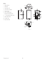
K12.2
1. ABS enclosure
2. Steel grille
3. Front power LED
4. Cast aluminum handles
5. Power module
6. M10 installation points
7. M8 yoke attachment points
8. 7.5° Downward-tilt pole socket
9. Vertical pole socket
10. Pull-back ring
11. Slip-resistant feet
— Figure 3 —
K.2 Series
1
4
7
5
6
7
9
8
3
1
7
4
10
10
11
11
6
1111
4
12
2
7

7
TD-000523-01-E
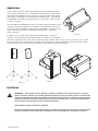
Applications
The K.2 Series has been primarily designed for portable audio reinforcement.
This includes a variety of uses in reinforcement for entertainers and presenters.
All are designed to perform well on their own in full-range audio. They can be
used singly, in stereo pairs or in distributed or delayed systems. They perform
extraordinarily well as both main reinforcement systems and as floor monitors
as shown in Figure 4.
All three models are equipped with two 35 mm pole sockets that allows use on
a speaker stand or on a pole over a subwoofer. (The subwoofer must have a
35 mm pole socket capable of supporting the loudspeakers.) One socket is for
vertical mounting, the other for tilting the enclosures down 7.5 degrees.
(RefertoFigure 5)
In addition, the K.2 Series have features designed for various suspension
methods. They feature two M10 threaded inserts for suspension with eyebolts
and a built-in pull-back ring. There are also yoke accessories (model numbers: K8.2 YOKE, K10.2 YOKE, K12.2 YOKE)
for each model that can mount either to the sides of the cabinet or to the top and bottom. These yokes allow for rigid
mounting to structures and rotation of the speaker system. (Refer to Figure 6 andFigure 7)
Installation
WARNING!: Before placing, installing, rigging, or suspending any speaker product, inspect all hardware, suspension,
cabinets, transducers, brackets and associated equipment for damage. Any missing, corroded, deformed, or non-load rated
component could significantly reduce the strength of the installation or placement. Any such condition severely reduces the
safety of the installation and should be immediately corrected. Use only hardware which is rated for the loading conditions
of the installation and any possible short-term, unexpected overloading.
Never exceed the rating of the hardware or equipment.
Consult a licensed, professional engineer regarding physical equipment installation. Ensure that all local, state and national
regulations regarding the safety and operation of loudspeakers and related equipment are understood and adhered to.
— Figure 4 —
— Figure 5 —
— Figure 6 —
— Figure 7 —

8
TD-000523-01-E
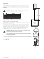
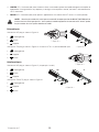
Deployment
The K.2 Series loudspeakers were designed to sit on the floor, stage, a subwoofer
enclosure, be suspended, or be pole mounted on a 35 mm diameter loudspeaker
support pole. If you are going to pole-mount on a subwoofer, refer to the chart below
for specifics.
WARNING!: Do not use a loudspeaker support pole longer than the lengths
specified in the table below when supported by a subwoofer.
K.2 Series
Subwoofers
KS212C KW181 KSUB
K8.2 36 in (914 mm) 36 in (914 mm) 31 in (787 mm)
K10.2 36 in (914 mm) 36 in (914 mm) 28.5 in (724 mm)
K12.2 36 in (914 mm) 36 in (914 mm) 26.5 in (673)
Integrated Suspension Points (suspended installations)
Refer to TD-000289 for M10 eye bolt installation.
The K8.2, K10.2 and K12.2 enclosures each feature two load-rated M10 installation
points and a built-in pull-back ring.
As shipped from the factory, each pick point has a adhesive cover installed to retain
the sleek look of the enclosure. These installation points are designed for use with
the eyebolts included in the available accessory kit, model number M10 Kit-C. The
installation points may also be used with any forged shoulder eyebolt with an M10
thread, provided the length of the thread is no more than 0.8inch (20 mm).
WARNING!: Make sure all suspension-point fasteners are installed and correctly
tightened in order to maintain enclosure’s ratedstrength.
Consult a licensed, professional engineer when any doubt or questions arise regarding a
physical equipment installation.
The K.2 Series loudspeakers each have two M10 suspension points, and one pull-back ring.
1. M10 suspension points
2. Pull-back ring
— Figure 8 —
K8.2
K10.2
K12.2
KS212C
KW181
Maximum
36 in
(914 mm)
— Figure 9 —
1 1
2

9
TD-000523-01-E
Cooling
This is a powered loudspeaker containing an internal power amplifier that produces heat. Allow a minimum of 6" (152
mm) clearance at cabinet back for convection cooling. Keep anything that might restrict airflow away from the rear of the
enclosure (i.e draperies, walls, etc.)
CAUTION!: Do not install enclosures with their rear panels exposed to direct sunlight. Direct sunlight will
heat the amplifier module and reduce its ability to produce full output. Install sunshades if needed. Maximum
ambient temperature for full performance to specification is 50° C (122° F). Do not install enclosures where
exposed to rain or other water sources. The enclosure is not weatherproof. Outdoor installations must provide
protection from the elements.
AC Mains
Refer to Figure 10)
Connect the AC power cord to the IEC socket on the back of the amplifier. Make
sure the plug is fully inserted into the IEC socket on the power amplifier module.
NOTE: Make sure that the AC power switch is in the OFF position
before connecting AC power cord to the AC source.
Connect the AC Power cord to the facility’s AC outlet.
The V-LOCK power cord has a special latching feature to prevent the power cord
from being unintentionally removed. The IEC plug and socket are both blue in color
so the power cord can be identified as a K.2 Series loudspeaker cord. If the QSC-
supplied cord is lost or damaged, a standard 18-gauge IEC power cord may be
used. However, the latching system works only with a V-LOCK power cord. Available from QSC.
The K.2 Series loudspeakers are equipped with a universal power supply that can use input AC power voltages ranging
from 100–240VAC at 50 – 60 Hz.
WARNING!: Use only the power cable that is correct for your location.
AC Mains Disconnection
Push in on the bottom of the rocker switch to turn the powered loudspeaker off. Unplug the AC cable from the power
source. To remove the AC mains cord from the amplifier, grasp the IEC connector’s plastic body, press the yellow latch
release button and pull.
Power Switch
Push in on the top of the rocker switch to apply AC mains power to the amplifier. When power is applied to the amplifier,
the blue POWER indicator LED illuminates.
Rear LED POWER Indicator
The blue LED POWER indicator on the rear panel will illuminate when the AC Power is applied. The rear LED POWER
indicator will extinguish when the AC Power has been removed.
If the rear LED POWER indicator does not illuminate within the first 3 minutes after power is applied, verify the AC mains
line cord is properly attached to the loudspeaker and plugged into the AC outlet. Verify the outlet is functioning properly.
NOTE: If the AC mains cord is usable and the AC mains outlet is operating properly, but the unit fails to
operate, the loudspeaker may require servicing. Contact QSC’s Technical Services department.
— Figure 10 —

10
TD-000523-01-E
System Power Sequencing
Proper power turn on/turn off sequencing can help to prevent unexpected sounds from being produced by the system
(pops, clicks, thumps). Always follow the rule that speakers are “last on, first off”.
Power On Sequence: Bring the output level control of the mixer (or other audio source) feeding your speakers to its
minimum position. Turn on all source devices (CD players, mixers, instruments), turn on subwoofer, then turn on the “top-
boxes” ( K8.2, K10.2 and K12.2). The level controls on your mixer may now be brought up.
Power Off Sequence: Turn off “top boxes,” turn off subwoofer, then turn off all source devices.
If a K.2 Series speaker is being driven from the output of another K.2 Series unit, it should be turned on after the unit
feeding it signal, and turned off before the unit feeding it signal.
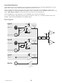
Block Diagram
— Figure 11 —
HF
Amp
Line / Hi-Z
Gain
Line
Hi-Z
Hi-Z
Hi-Z
Signal
Mono In
Gain
Hi-Z/Line Thr u
HI-Z/Line In
Input B
Mic/Line Thr u
Mic/Line In
Input A
Mic
Pre
Mic
Signal
Mic / Line
Gain
Mic
Line
Stereo In
Mix Out
Sum
DSP
LF
Amp
HF
Amp
Delay
Preset
Contours
Limit
Sum
Input C
Signal

11
TD-000523-01-E
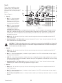
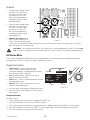
Inputs
The K.2 Series amplifier has three
separate inputs; two combination
XLR/1/4” Phone Jack (Inputs A and
B) and one 1/8” (3.5 mm) TRS jack
(Input C).
Refer to Figure 12
1. Input A
a. SIG LED – When illuminated
(green), it indicates a signal
is present. If this LED is not
illuminated, the input signal is
missing or too low to detect.
b. MIC LED – When illuminated
(yellow) it indicates the input
is configured to accept a
microphone input. When not
illuminated, it indicates the input is configured for a line-level input. You can change the setting through the Menu.
When MIC is selected, the MIC Pre-amp is activated, and the yellow MIC level LED illuminates. The MIC setting
should only be used if a microphone is connected directly to the MIC/LINE input. Note that the input does not
provide phantom power.
c. GAIN knob – Sets the sensitivity of Input A which controls the signal level sent to the amplifier and the MIX OUT
(POST GAIN) output.
d. Combination XLR – 1/4” Phone Jack connector. Balanced XLR and 1/4” input. Accepts line-level or MIC-level
inputs. Select MIC or Line through the Menu.
CAUTION!: The MIC setting should only be used if a microphone is connected directly to the MIC/LINE input. Using the MIC
setting for line-level may introduce distortion. Use caution when changing to the MIC selection in the Menu as the output level
increases significantly when MIC is selected.
2. Input B
a. GAIN knob – Sets the sensitivity of Input B which controls the signal level sent to the amplifier and the MIX OUT
(POST GAIN) output.
b. SIG LED – When illuminated (green), it indicates a signal is present. If this LED is not illuminated, the input signal is
missing or too low to detect.
c. HI-Z LED – When illuminated (yellow) it indicates the input is configured to accept a high impedance input, typically
a musical instrument. When not illuminated, it indicates the input is configured for a line-level input. You can change
the setting through the Menu.
d. Combination XLR – 1/4” Phone Jack connector. Balanced XLR and 1/4” input. Accepts line-level and high
Impedance inputs. Select line level or high impedance through the Menu.
3. Input C
a. GAIN knob – Sets the sensitivity of Input B which controls the signal level sent to the amplifier and the MIX OUT
(POST GAIN) output.
b. SIG LED – When illuminated (green), it indicates a signal is present. If this LED is not illuminated, the input signal is
missing or too low to detect.
c. Stereo 1/8” (3.5 mm) TRS connector – Accepts line-level stereo input. Stereo input received at Input C is summed
to mono.
— Figure 12 —
2a
1a
1b
1c
1d
2b
2c
3a
3b
3c
4
5
2d

12
TD-000523-01-E
4. LIMITER LED – Illuminates (red) when the built-in limiter is activated to protect and avoid damage to the amplifier or
loudspeaker. If the signal level at any frequency is too high, or the amplifier is too hot, the limiter is activated and the
LED is illuminated.
5. POWER LED – Illuminates (blue) when power is applied to the unit and the ON/OFF switch is in the ON position.
NOTE: Unless the gain controls of all active inputs are set to 0 dB, the output signal from the MIX OUT (POST GAIN) will not
be at the same level as the input signal. If a “slave” speaker is intended to playback at the same level as the “master” speaker,
the gain control on the “slave” speaker should be set to0 dB.
Balanced Inputs
Connect the XLR plug as shown in Figure 13.
1. Shield (ground)
2. Positive
3. Negative
Connect the TRS plug as shown in Figure 14. Do not use a TS 1/4” jack for balanced input.
1. Shield (ground)
2. Negative
3. Positive
Unbalanced Inputs
Connect the XLR plug as shown in Figure 15. (Jumper pins 1 and 3.)
1. Shield (ground)
2. Positive
3. Negative
Connect the TRS or TS plug as shown in Figure 16.
1. Shield (ground)
2. Negative
3. Positive
— Figure 13 —
— Figure 14 —
— Figure 15 —
— Figure 16 —
TRS TS

13
TD-000523-01-E
Outputs
1. Channel B pass-through output
connector. The signal here is
the same as the input signal
on Channel B. Use this to
daisy-chain loudspeakers or
to provide the signal to other
audioequipment.
2. Channel A pass-through output
connector. The signal here is
the same as the input signal
on Channel A. Use this to
daisy-chain loudspeakers or
to provide the signal to other
audioequipment.
3. MIX OUT (Post Gain) output
XLR is a mix of Channels A, B,
and C. The line-level output signal
is Post Gain. Any adjustments made to the gain of any of the three channels affects this output signal. This output
does not contain any DSP processing.
CAUTION!: Do not connect the MIX OUT (Post Gain) of a K.2 Series loudspeaker to any INPUT of the same
unit. This output is designed to send the mixed signal to OTHER K.2 Series units or to other audioequipment.
K.2 Series Menu
The K.2 Series loudspeakers provide a multi-function digital display for control and selection of loudspeaker functions
including presets, scenes, cross-over, EQ, delay and frequency contour.
Display Introduction
1. Home Screen – Displays input types (MIC,
Line, HI-Z) for channels A and B, and main
functionalityheadings. Light background with black
text indicates the item is selected.
2. Exit, or go back button – press to return to the
previous screen or menu level.
3. Enter button – confirm a selected parameter or open
the selected menuitem.
4. Selector knob – move to another menu item, or
change a selected parameter.
5. Left side, Home screen displays the parameter name.
6. Right side, Home screen displays the current state of
the parameter.
Navigation Example:
To select a Preset:
1. Turn the Selector knob (4) clockwise to highlight the PRESET line.
2. Press the Enter button (3) to access the PRESET submenu.
3. Turn the Selector knob (4) clockwise or counterclockwise as needed to highlight the PRESET you wish to recall.
4. Press the Enter button (3) to recall the PRESET. A small triangle displays next to the recalled (active) PRESET.
5. Press the Exit button (2) to return to the Home screen.
— Figure 17 —
1
2
3
— Figure 18 —
EQ: IN
A: LINE
PRESET: DEFAULT
NO SUB
DELAY: 0 ms
SETTINGS
B: Hi-Z
:
1
2 3 4
5 6

14
TD-000523-01-E
Menu Map
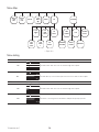
Menu Listing
INPUT A: Select the sensitivity of input A
LINE
LINE
MIC
INPUT A
Use with mixers and other sources that have high-level outputs.
MIC
YES
NO
SWITCH TO MIC
ARE YOU SURE?
INPUT A
Use with directly connected microphones and sources with low-level output.
INPUT B: Select the sensitivity and impedance of input B
LINE
LINE
INST
INPUT B
Use with mixers and other sources that have high-level outputs.
INST
YES
NO
SWITCH TO INST
ARE YOU SURE?
INPUT B
Use when connecting musical instruments with passive pick-up systems.
— Figure 19 —
SETTINGS
PRESET
SUB
MENU
EQDELAY
PEQ
BAND
1
PEQ
LOW
SHELF
EQ
RESET
RECALL
SCENES
PEQ
HIGH
SHELF
PEQ
BAND
2
LED
EQ
IN/OUT
SAVE
SCENES
INPUT A
LINE
MIC*
INPUT B
HI-Z
LINE
FACTORY
RESET
CONTRAST
FIRMWARE
VERSION

15
TD-000523-01-E
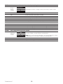
PRESETS Select a pre-programmed EQ and dynamic processing setting for specific applications
Factory
Presets
Example
BASS AMP
HAND MIC
FACTORY PRESETS
AC GUIT/VOX
Use the Selector knob to scroll (up or down) to the Preset you wish to recall.
DEFAULT The basic voicing of the loudspeaker
LIVE For live sound reinforcement and vocal clarity
LIVE BRIGHT Similar to LIVE with some high-frequency boost to balance the sub
DANCE Low and high frequency emphasis
STAGE MONITOR 1 For most stage monitor uses, reduces excessive bass build-up on stage
STAGE MONITOR 2 For stage monitor use when low frequency reproduction is needed
AC GUIT / VOX For Acoustic Guitars and VOX
BASS AMP For direct connection of bass instruments
HAND MIC For speech intelligibility and feedback reduction using a hand-held microphone.
HEAD MIC For speech intelligibility and feedback reduction using a head microphone.
STUDIO MON For use as a recording monitor
SUB MENU Select a setting to match the top-box with a subwoofer
SUB Menu
Example
80 Hz KS
100 Hz K – KW – KLA
SUB MENU
NO SUB
In the example, the 80 Hz KS high-pass filter is selected. Use the Selector knob
to scroll to the filter you need, then press the Enter button.
NOTE: All crossovers share the same phase – the only time alignment to make is
compensating for the actual distance between sub and top boxes
NO SUB For use without a subwoofer
80 Hz KS Applies an 80 Hz High Pass Filter (HPF)

16
TD-000523-01-E
100 Hz K – KW – KLA
Applies a 100 Hz High Pass Filter (HPF) (For use with a K-SUB, KW Sub, or KLA Sub)
125 Hz Applies a 125 Hz High Pass Filter (HPF)
DELAY Adjust the signal delay for rear fill and similar applications.
Delay
1.13
0.43
DELAY
1.00 ms
FEET
METERS
0 –100 milliseconds, 0 – 113 feet, 0 – 34 meters
All units of measure change together when the Selection knob is turned.
EQ Adjust the 4-band, parametric equalizer
EQ Example
EQ1
EQ2
EQ
HIGH
LOW
EQ IN
-1.55
-1.43
-2.0
-1.25
2.00k
600.0
8.30k
200.0
0.7
0.7
RESET
dB Hz Q
In the example, EQ1 is selected. Press the Enter button to adjust. When you are
finished, press the Enter button to make the change, or the Exit button to exit
without changing the parameter.
dB Hz Q
High Shelving Band
Default
0.0 dB to -6.0 dB
0.0 dB
1.0 kHz to 10.0 kHz
8.0 kHz
N/A
EQ1 (EQ for Band 1)
Default
0.0 dB to -6.0 dB
0.0 dB
50 Hz to 20.0 kHz
1.0 kHz
0.4 to 4.0
0.7
EQ2 (EQ for Band 2)
Default
0.0 dB to -6.0 dB
0.0 dB
200 Hz to 20 kHz
1.0 kHz
0.4 to 4.0
0.7
Low Shelving Band
Default
0.0 dB to -6.0 dB
0.0 dB
100 Hz to 500 Hz
100 Hz
N/A
EQ IN/OUT Engages / bypasses the equalizer
RESET Returns the EQ to the flat, default settings
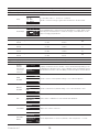
SETTINGS Utility Functions
Displays
firmware
version and
other menu
selections
RECALL SCENES
LED
K10.2 1.0.6.2844
SAVE SCENES
CONTRAST
FACTORY RESET
Displays the firmware version number – cannot edit this field. Depending on the
loudspeaker model, K8.2, K10.2, or K12.2 displays next to the firmware version.
Use the Selector knob to select the Utility you want, then press the Enter button.
SAVE
SCENES
SAVE
BACK
USER 1
USER 2
SAVE SCENE TO
USER 3
Used to save the current speaker settings to one of five user presets
RECALL
SCENES
LOAD
BACK
DEFAULT
USER 1
RECALL SCENE
USER 2
Used to recall the factory default setting or one of the saved user scenes
LED
FRONT AND REAR
REAR ONLY
LED
FRONT ONLY
Selects which combination of front and rear LEDs illuminate
CONTRAST
LEVEL 8
CONTRAST
TEST TEXT
Adjusts the contrast of the LCD
FACTORY
RESET
YES
NO
USER PRESETS AND
SETTINGS WILL BE
SET TO DEFAULT
FACTORY RESET
CONTINUE?
Resets all parameters to the factory defaults, clears user presets – no undo.

17
TD-000523-01-E
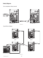
Hookup Diagrams
Two Loudspeakers Daisy-chained
Typical Stereo System
— Figure 20 —
— Figure 21 —
LEFT RIGHT

18
TD-000523-01-E
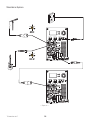
Standalone System
— Figure 22 —
HI-Z
MIC

19
TD-000523-01-E
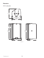
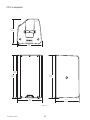
Dimensions
K8.2 Loudspeaker
— Figure 23 —
K.2 Series
17.5 in
445 mm
17.7 in
449 mm
11 in
280 mm
17.7 in
449 mm
10.6 in
269 mm
11 in
280 mm
10.6 in
269 mm

20
TD-000523-01-E
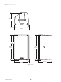
K10.2 Loudspeaker
— Figure 24 —
K.2 Series
20.0in
515 mm
20.4 in
519 mm
20.4 in
519 mm
12.6 in
320 mm
11.8 in
300 mm
12.6 in
320 mm
11.8 in
300 mm
Page is loading ...
Page is loading ...
Page is loading ...
-
 1
1
-
 2
2
-
 3
3
-
 4
4
-
 5
5
-
 6
6
-
 7
7
-
 8
8
-
 9
9
-
 10
10
-
 11
11
-
 12
12
-
 13
13
-
 14
14
-
 15
15
-
 16
16
-
 17
17
-
 18
18
-
 19
19
-
 20
20
-
 21
21
-
 22
22
-
 23
23


