ESAB ES 200i Pro User manual
- Category
- Welding System
- Type
- User manual
This manual is also suitable for
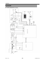
ESAB Rogue ES 180i Pro, ES 200i Pro is an inverter-based welding machine designed for MMA (Manual Metal Arc) and TIG (Tungsten Inert Gas) welding. It delivers smooth and stable welding performance for both welding methods. With its compact size and portability, it is ideal for a variety of welding tasks both indoors and outdoors. It features adjustable welding parameters, allowing you to fine-tune your welds, and comes with a range of accessories for added versatility.
ESAB Rogue ES 180i Pro, ES 200i Pro is an inverter-based welding machine designed for MMA (Manual Metal Arc) and TIG (Tungsten Inert Gas) welding. It delivers smooth and stable welding performance for both welding methods. With its compact size and portability, it is ideal for a variety of welding tasks both indoors and outdoors. It features adjustable welding parameters, allowing you to fine-tune your welds, and comes with a range of accessories for added versatility.


-
 1
1
-
 2
2
-
 3
3
-
 4
4
-
 5
5
-
 6
6
-
 7
7
-
 8
8
-
 9
9
-
 10
10
-
 11
11
-
 12
12
-
 13
13
-
 14
14
-
 15
15
-
 16
16
-
 17
17
-
 18
18
-
 19
19
-
 20
20
-
 21
21
-
 22
22
-
 23
23
-
 24
24
-
 25
25
-
 26
26


ESAB ES 200i Pro User manual
- Category
- Welding System
- Type
- User manual
- This manual is also suitable for
ESAB Rogue ES 180i Pro, ES 200i Pro is an inverter-based welding machine designed for MMA (Manual Metal Arc) and TIG (Tungsten Inert Gas) welding. It delivers smooth and stable welding performance for both welding methods. With its compact size and portability, it is ideal for a variety of welding tasks both indoors and outdoors. It features adjustable welding parameters, allowing you to fine-tune your welds, and comes with a range of accessories for added versatility.
Ask a question and I''ll find the answer in the document
Finding information in a document is now easier with AI
Related papers
-
ESAB Rogue ES 180i Pro, ES 200i Pro User manual
-
ESAB ES 150i User manual
-
ESAB ES, ET Series Rogue Operating instructions
-
ESAB Rogue ET 180i User manual
-
-
ESAB Rogue ES 150i User manual
-
ESAB Arc 180 User manual
-
-
-
Other documents
-
Dataflex 52.672 Datasheet
-
 Lotos TIG200DC User manual
-
CIGWELD ES 150i Pro ES Operating instructions
-
 Magmaweld MONOTIG 220ip User manual
-
Roland M-200i Owner's manual
-
-
WIA Weldarc 200i AC/DC Owner's manual
-
Hyundai MMA series User manual
-
Drazice OKC 125 NTR/HV Operating and Installation manual
-

