Page is loading ...

WARNING: OPERATOR MUST READ AND UNDERSTAND THIS MANUAL COMPLETELY
BEFORE OPERATING THIS EQUIPMENT.
Upright Extractor
OPERATORS MANUAL AND PARTS LIST
Model PFX1350 SERIES
X8607 12/2004

2
IMPORTANT SAFETY PRECAUTIONSIMPORTANT SAFETY PRECAUTIONS
WWAARRNNIINNGG!!::
To reduce the risk of fire, electric shock, or injury
When using this upright extractor, basic precautions should
always be followed, including the following:
1) DO NOT leave unit when plugged in. Unplug from outlet when not
in use and before servicing.
2) DO NOT allow unit to be used as a toy. Close
attention is necessary when used around or near children.
3) Use only as described in this manual. Use only
manufacturer’s recommended attachments.
4) DO NOT use with damaged cord or plug. If unit is not working
properly because it has been dropped, dropped into water, left
outdoors, or damaged in any way, contact a service center of
Powr-Flite.
5)
DO NOT handle plug or appliance with wet hands.
6) DO NOT put any objects into openings. DO NOT use with any
opening blocked: keep free of dust, lint, hair
, or anything that may
reduce air flow.
7) Keep hair, loose clothing, fingers, and all parts of body away from
openings and moving parts.
8) DO NOT pick up anything that is smoking or
burning such as cigarettes, matches, or hot ashes.
9) DO NOT use to pick up hazardous chemicals.
10) Turn off all controls before unplugging.
11) Turn unit off immediately if foam or liquid comes from machine
exhaust. Empty & clean out recovery (dirty) tank and use defoamer
to correct the problem.
12) DO NOT use to pick up flammable or combustible liquids such as
gasoline or use in areas where they may be present.
13)
DO NOT use where oxygen or anesthetics are used.
14) Replace damaged or worn parts immediately with genuine original
equipment parts to maintain safety
.
15)
This unit must be connected to a properly grounded outlet only
.
See grounding instruction on page 4.
WARNING
To avoid fire, DO NOT
use with a flammable
or combustible liquid
to clean floor.
WARNING
To avoid electric
shock, DO NOT
expose to rain.
Store Indoors.

3
GROUNDING INSTRUCTIONS
DANGER: Improper use of the grounding plug can result in a risk of electric shock.
GROUNDING INSTRUCTIONS
GROUNDING METHODS
This extractor must be properly grounded. If it should malfunction or breakdown, grounding pro-
vides a path of least resistance for electrical current to reduce the risk of electric shock. This
machine is equipped with 1 or 2 pigtail cords having an equipment-grounding conductor and
grounding plug. The pigtails must be inserted into an appropriate 12 gauge 3 prong extension cord.
This unit is for use on a nominal 120 volt circuit and has a
grounded plug that looks like the plug illustrated in
(Fig. A).
WARNING!
Improper connection of the equipment-grounding conductor can result in a risk of
electric shock. Check with a qualified electrician or service person if you are in
doubt as to whether the outlet is properly grounded. DO NOT modify the plug pro-
vided with the appliance. If it will not fit the outlet, have a proper outlet installed by
a qualified electrician.

4
General instructions for PFX1350 series Extractors
Congratulations on your purchase of a Powr-Flite extractor. You are now equipped to handle any and all commercial carpet
cleaning jobs. .
Shipping and Damage
This equipment is thoroughly inspected, tested, and packaged to provide equipment in good operating condition. It is beyond
our control after the equipment is turned over to a freight carrier. The freight carrier received and signed for the equipment in
good condition. Consequently, it is most important to protect your interest by carefully complying with the following instructions:
Please inspect your cartons for any damage (including concealed damage) that might have occurred during shipment. Any dam-
age is the responsibility of the freight carrier and should be reported to the freight carrier immediately. It is your responsibility to
issue a claim and to receive compensation from the freight carrier for any damage done in transit. Damage of this sort is not
warranted.
Follow these easy step by step instructions to ensure proper operating performance.
1. Fill up the fresh water solution tank with tap water that is
120-135 degrees and approved carpet cleaning chemical
if you are not pre-spraying your chemical on the carpet.
2. Attach two 12 gauge extension cords (NOT INCLUDED)
(one cord for non-heated models) to each of the pigtail
cords located on the lower backside of the unit. The red
pigtail powers the heater while the black pigtail powers
the vacuum motors and pump.
3. Plug each extension cord into a separate and grounded
20 amp wall socket circuits, when this is accomplished
the green indicator light will be lit (on heated models).
4. Attach the hose system to the unit and to your carpet
wand.
5. Turn on the heater and the pump to the "on" position,
(only pump on non-heated models) when the heater is on
the orange indicator light on the switch panel will be lit.
6. With the solution line attached to the wand and the
machine, prime the pump by squeezing the trigger on the
wand releasing the water (hold wand tip over solution
tank to put water back into solution tank). This will
pump water into the heater and get any air out of the
solution line. Let the heater heat up this will take
3 to 5 minutes. *Prime pump on 400 p.s.i. models
with prime hose (included).
7. Turn vacuum switches to the "on" position one at at time
to begin cleaning.
8. Anyone designated to operate this equipment must,
without fail, read and thoroughly understand all
instructions and precautions prior to use.
9. Never use equipment out of doors or in the rain.
10. Never use flammable or explosive materials in
or around this equipment!!!
11. When vacuum tank is full, empty by using drain hose at
rear of machine. If a pail is used to empty the vacuum
waste tank, do not use the same pail to fill the solution
tank as this can result in putting dirt and grit into the
solution line that can plug filters, orifices, and generally
degrade the solution line system (do not reuse solution).
12. To empty solution tank, detach the wand from the end of
the vacuum hose and insert the vacuum hose into the
solution tank. Turn the vacuum switches to "on" position
and transfer solution to vacuum tank and dispose of as
outlined in #11. Clean vacuum stack filter at this time.

5
Maintenance
To receive reliable service from this equipment, regular daily
maintenance is a requirement. Fabric cleaning, both carpet
and upholstery, are very dirty environments for any equipment.
The following recommendations are offered.
1. Keep the equipment clean, both inside and out.
2. Lubricate brass quick disconnects and drain valves with
a quality lubricant such as WD-40.
3. Flush solution systems after use with clear, clean water.
(A white vinegar solution may also be used). This will
counter-act hard water and alkaline deposits and aid
in keeping orifices clean.
4. Do not allow fluid either in solution or waste tank to sit
overnight. The unit should be emptied and cleaned daily.
5. Clean the strainer in the solution tank, the filters on the
vacuum stack in vacuum tank and all lint filters in the
inlet or vacuum tanks daily.
6. Do not use the same receptacle (pail) to fill solution
tank that is used to remove waste from vacuum tank.
7. When the unit is not in use, leave the vacuum tank lid
open.
8. At the end of each day, run the vacuum for 3 minutes
with lid open and filter off.
Safety Precautions
These precautions are designed with the safety of the operator,
the equipment, and others in mind and must be followed at all
times to avoid serious personal harm and/or death, and dam-
age to the unit.
1. Always use a grounded electrical outlet.
2. Always disconnect electric cable from electrical outlet
before attempting to make any adjustments or repairs.
3. Never use this equipment as a toy.
4. Never use equipment near or around flammable or
explosive materials, fuels, or solvents.
5. Never put flammable materials, fuels, or solvents
into equipment.
6. Never lift the machine by the drain hose.
7.
Do not allow the unit to freeze!
8. The equipment was not designed to be used outdoors
or in the rain.
9. Do not operate in standing water.
10. Wear safety equipment and clothing to protect from
extremely hot water.
11. Do not operate equipment under any unsafe condition.

6
12. Do not operate if pigtails, hoses, etc. are cracked, frayed,
leaking, or otherwise in need of repair.
13. Common sense is a powerful force in protecting the
operator, the equipment and others from serious damage
injury and/or death.
Storage of Equipment
1. Store extractor indoors in dry area.
2. Recovery and solution tank should be empty and clean
when the extractor is not in use.
3. Leave the recovery lid and dump valve open to air out the
recovery tank.
4. Do not store in freezing temperature.
5. A small amount of windshield washer fluid available at an
auto supply may be left in the pump and internal solution
line for protection against freezing.
Warnings
1. Do not break off or pull the grounding prong on the plug.
2. Do not attempt repair on a warrantied machine unless
instructions to perform it by an authorized shop are
obtained from the factory.
3. Do not use citrus-based (D-Limonene) cleaners in this
machine.
4. Do not use cleaning chemicals in this machine except
those recommended for steam-type extraction equipment.
The use of any chemicals with abrasive additives voids the
warranty.
5. Do not use any replacement parts except those specified
on the parts list. Performance of the machine
could be affected if substitutions are made.
6. Do not use water in excess of 140° F (62° C) through
the pump system. It could damage the seals and
polyprophene casing of the diaphram pump.
7. Follow maintenance schedule strictly.
8.
Failure to comply with the above warnings
instructions will void the warranty.
ONE LAST REMINDER
Read All Instructions, Warning and Cautions Before Using. These guidelines are presented for
your protection and convenience. Please read them carefully, since failure to heed these
precautions could result in discomfort or injury. When using an electrical appliance, basic
safety precautions should always be followed.
WARNING
TO AVOID FIRE, DO NOT USE WITH A FLAMMABLE OR COMBUSTIBLE
LIQUID TO CLEAN FLOOR.

7
M
ODEL PFX1350 SERIES CARPET EXTRACTOR PARTS
ref# order# description
1 X9113 housing, recovery tank
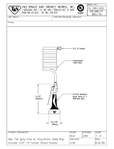
2 PX25 fitting, plastic, hose barb
3 PX14A dump valve gasket rubber
4 PX11A fitting, plastic elbow
5 72486A spacer, 1.625 long, .50 od, .313 id
6 X8025 wheel, black, 4” x 1-1/4”
7 72645A bolt, 5/16-18 x 2-1/4, hex
8 PX103G gasket, lid, 8”od x 6-5/8 id x 1/8” thick
9 PX103 lid, screw-in, 6” clear w/ black ring
10 72656A hose, 1-1/2”, wire-reinforced, black
11 X8295 screw, black zinc
12 PX33 vacuum tube
13 PX31 float cage w/ heavy ball
14 72615A coupling, pvc, 1-1/2 slip x slip
ref# order# description
15 X9154 pipe, pvc, schedule 40, 1-1/2”, 9.5” long
16 PX63 coupler
, plastic, 1- _” slip
17 PX87 rocker switch
18 X8102 neon light w/ lens, orang
19 72387A screw, #8 x 5/8 phil ph black
20 PX86 indicator light, green, 250v
21 X9152 switch panel w/o heater
X9130 switch panel w/ heater
22 PAS36 expansion plug drain
23 PAS37 drain hose
24 7DL005 clamp worm gear 1-1/2 ss
25 X8235 washer, _” flat, uss zinc
26 7GR016 elbow, 1-1/4h - 1-1/4m, nylon
P
FX1350 recovery tank assembly

8
M
ODEL PFX1350 SERIES CARPET EXTRACTOR PARTS
P
FX1350 base assembly

9
M
ODEL PFX1350 SERIES CARPET EXTRACTOR PARTS
ref# order# description
1 X9112 housing, solution tank
2 X9014 hinge
3 7BS003 screw, phil pan ms, 18-8 ss
4 PX3H hose, solution, 3/8" id x 1/8" wall
5 PX42 clamp, 5/8 worm gear
6 PX85 fitting, hose male/male barb
7 PX17 street elbow, 45° brass, 1/4" npt
8 PX48 fitting, brass, bulkhead, 3/4
9 72274A washer, 3/4"
10 PX48G gasket, fiber
11 71495A pump protection filter
12 7CT002 bolt, 5/16-18 x 1" hex tap
13 PX88 grommet
14 7CM002 washer, flat #8 ss, toggle valve
15 X9140 tie down plate
16 7CP002 bolt, 5/16-18 x 1/2" hex tap
17 7BH004 screw, 10-32 x 3/8" phil pan ms
18 72173A spring clip, black vinyl coated
19 X8218 washer, 5/16 sae flat zinc
20 X9149 gasket, foam strip
PFX1350 solution tank assembly
r
ef# order# description
1 72620AB housing, base, black
2 72633A axle
3 X9066 wheel, 12" x 1.75" non-marking,
PX106B wheel, 12" w/ 3/4" bore, all black
4 7GL002 push nut
5 7CM007 washer, 1/2 uss flat, 18-8 ss
6 72634A bushing, 1/2" id x 3/4" od x 2-1/4" long
72635A spacer, 1/2" id x 3/4" od x 1/4" long
7 72640A gasket, vac manifold, long
8 72623A cover, vacuum manifold, long
9 7CW002 screw, #6 x 3/4 phil pan ts, type a 18-8 ss
10 72000A rod, 3/16 x 5-1/2, all thread stud, 18-8 ss
11 72657A screw, 10-24 x 4" long, hex head
72658A screw, 10-24 x 5" long, hex head
12 72651A spacer, vac motor, 2.375" long
13 70020B gasket, vacuum motor seal
14 1942-IE vacuum motor, 115 vac, 104 cfm, 2 stage
72365A vacuum motor, 3 stage, 120v
15 7BF003 nut, kep, #10-24 zinc
16 7CM003 washer, #10 uss flat, 18-8 ss
17 72624A cover, vacuum manifold, short
18 72641A gasket, vac manifold, short
19 PX117A gauge, 0-300 psi, 2-1/2", abs
PC38 connector, double thread
20 72638A pressure regulator plate
X9157 cover, pressure regulator plate
21 72173A spring clip, black vinyl coated
22 72636A cover plate, bottom
23 72388A screw, #10 x 5/8, tap phil, ss pan head
24 PX65 caster, 4" black
r
ef# order# description
25 72490A screw, 5/16-18 x 5/8, cap screw w/ hex socket
26 72387A screw, #8 x 5/8, black, tap phil, pan head
27 72639A gasket, mounting pressure regulator
28 X8256 nut, 8-32 keps, zinc
29 70063B coupler, valved 1/4, quick disconnect
30 7CX002 nipple, hex 1/4 mpt
31 72115A washer, 5/8 x 1-3/16, bonded seal, galvanized
32 PC38 connector, double thread, female
33 72642A gasket, vac manifold, circle
34 72625A cover, vacuum manifold, circle
35 72627A gasket, pump mounting
36 72626A pump mounting plate
37 X9069 end loop, ss, w/ 2 holes, 16g
38 PF1750 heater unit, 1750 watts
PF1200 heater, 1200w for low flow
PF2000 heater, 2 1000 watt element (split)
39 PT400 pump, 200 psi w/regulator, 115v
SF814 pump, 100 psi w/by-pass, epdm valves
PT400-KIT3 pump assembly, 400 psi w/ hoses
40 X9022 heater mounting bracket
41 X8236 screw, 10-24 x 1-1/4", phil pan ms, zinc
42 72020A screw, #12 x 1", self-tap, phms zinc
43 7BS003 screw, 1/4-20 x 1/2, phil, pan , ms 18-8 ss
44 X9014 hinge
45 PD8 strain relief, 1/2" npt
46 PX112 pigtail, black, 12/3 sjt x 39" long
47 PR112R pigtail, red, 12/3 sjt x 39" long
48 X9131 cord panel
49 X8008N nut, lock, 1/2" steel conduit
50 7BS002 screw, 8-32 x 1/2 phil, pan ms, 18-8 ss
P
FX1350 base assembly

10
Troubleshooting Information
ELECTRICAL SYSTEM
PROBLEM POSSIBLE CAUSE SOLUTION
No electrical power. 1. Defective power cord. 1. Replace
2. Circuit breaker off or 2. Turn circuit breaker
fuse blown. on or replace fuse.
Unplug any equipment
using the same circuit.
Switch is turned on. 1. Faulty electrical cable. 1. Repair or replace.
Intermittent power to 2. Defective switches. 2. Replace.
motor(s). 3. Loose terminal or dis- 3. Replace.
colored terminal connections.
Electrical Shock 1. Equipment not 1. Locate grounded
grounded. outlet.
VACUUM SYSTEM
PROBLEM POSSIBLE CAUSE SOLUTION
Vacuum motor on 1. Drain hose open. 1. Close drain hose.
Little or no vacuum Recovery tank lid must
on wand head. be closed.
2. Defective vacuum hose 2. Repair or replace.
hose. Kinks
in vacuum
hose.
3. Vacuum disconnected 3. Open machine, connect
vacuum hose to
recovery tank.
Not enough vacuum 1. Damaged recovery 1. Replace
power at the machine. tank lid.
2. Lint clogging ball - 2. Remove screen.
type shutoff screen. Clean out fibers and
accumulated dirt.
3. Vacuum hose connection 3. Check for leaks
between stand pipe and around clamps and cuffs
vacuum motor. (tighten). Replace damaged
hose(s).
4. Vacuum motor 4. Check air flow by
exhaust blocked. removing hose from
machine and feel the
exhaust under the
machine. Remove
obstruction.
5. Cords not plugged into 5. Relocate one cord to a
seperate circuits
different room.
V
ACUUM
SYSTEM
PROBLEM POSSIBLE CAUSE SOLUTION
Motor running and no 1. Faulty vacuum motor. 1. Replace.
vacuum at all.
No exhaust from the 2. Water shutoff closed. 2. Clean water shutoff
blowport. screen.
Premature closing of 1. Dirty or clogged shut- 1. Remove and clean
ball type shutoff. off filter screen. screen.
Ball
type shutoff 2. Ball coated with 2. Remove and rinse
failing
to
release after detergent or other ball with clean water.
recovery tank is drained. foreign material.
2.
Screen
slightly
out of 3. Bend screen by
round. squeezing slightly by
hand until there is an
obvious
space between
ball and inside of screen.
Foam/dirty solution 1. Foam from carpet by- 1. Use additional
c
oming out of vacuum passing water shutoff. defoamer.
exhaust port. 2. Elbow in vacuum tank 2. The elbow should be
i
s not positioned pointed directly at the
correctly. side wall of the tank
away from the ball type
shutoff.
SOLUTION SYSTEM
PROBLEM POSSIBLE CAUSE SOLUTION
Pump motor on – 1. Clogged or faulty 1. Check intake on
no spray through jets. solution control valve. valve and remove lint
or other foreign
material.
2. Clogged or faulty 2. Depress plunger on
quick disconnect on solution hose against
housing. inside wall of solution
tank. If solution is flow-
ing at this point, the
system is O.K. If no
solution flows, check the
quick disconnect for lint
and other foreign matter.
3. Punctured pump 3. Replace with
diaphragm. diaphragm repair kit.
4. Clogged jets 4. clean jets on wand or tool.
PROBLEM POSSIBLE CAUSE SOLUTION
Uneven spray from 1. Clogged strainer in 1. Unscrew strainer
jet. Spray weak or solution tank. and remove lint and
uneven. any other foreign
material from screen.
2. Clogged jet. 2. Remove and clean.
Leaking or stuck 1. Foreign material in 1. Remove brass hex
solution valve. valve. plug, clean valve and
replace.
2.
Loose
brass hex nut. 2. Reseal hex and plug.
3. Valve worn or seals 3. Replace worn parts
worn. with solution valve
repair kit.
Pump
motor 1. Loose wiring 1. Tighten wiring
not working. 2. Defective pump 2. Replace with new
pressure switch
pressure switch assembly
3. Motor burnout 3. Replace pump motor
Pump pressure low 1. Clogged screens on 1. Unscrew strainer
strainer
in
solution tank
. remove lint and any
other foreign material
from
screen.
2. Punctured pump 2. Replace with
diaphragm. diaphragm repair kit.
3. Defective rectifier or 3. Replace.
motor.
4. Pump not primed 4. Plug priming hose into
solution connection and place
end in solution tank. Run
pump for 4 minutes
Pump pressure varies. 1. Worn carbon brushes. 1. Replace brushes.
2. Defective pump 2. Replace.
pressure control switch.

XXXXX 06/2005
3101 Wichita Court ■ Fort Worth, TX 76140 ■ 800.880-2913 ■ www.Powr-Flite.com
S
eries
Perfect Heat
Perfect Heat
TM
Plus System
WARNING! The Perfect Heat
TM
Plus System can produce very hot water that could damage some delicate
fabrics and fibers. Please ensure the surface being cleaned will not be damaged by hot water up to 200 degreEs
Fahrenheit.
This machine is equiped with the Perfect Heat
TM
Plus System for heating the cleaning solution. This system uses a com-
bination of the patent pending Perfect Heat
TM
coils and an inline electrical heater.
Operation:
1. Follow operating instructions steps for filling the machine with water and cleaning solution.
2. Turn on electrical heater, switch is located on panel.
3. Pre-heat machine for 5-10 minutes before use.
NOTE: There is a valve in the upper compartment that either sends the water through the heating components, or
bypasses them. The machine is preset in the “HOT” position. To clean with cold water, turn the valve to “COLD” or UP
position. This should be done prior to filling the tank with water. For general cleaning, it is recommended leaving the
valve in the “HOT” or down position and cleaning with hot water.
switch panel
valve

Ref # Part # Description Qty
01 72620AB Housing, Base, Black 1
02 72633A Axle, 23.375” Long 1
03 X9066+ Wheel, 12" x 1.75" Non-Marking, Gray Tire on Black Wheel 2
04 7GL002 Push Nut 2
05 7CM007 Washer, 1/2 USS Flat, 18-8 SS 6
06 72635A Spacer, 1/2" ID x 3/4" OD x 1/4" Long 2
07 72640A Gasket, Vac Manifold, Long 2
08 72623A Cover, Vacuum Manifold, Long 2
0
9 7CW002 Screw, #6 x 3/4 Phil Pan TS, Type A 18-8 SS 26
10 72000A Rod, 3/16 x 5-1/2, All Thread Stud, 18-8 SS 1
11 72658A Screw, 10-24 x 5" Long, Rnd Slot, Zinc, Fully Threaded 3
12 72605A Spacer, 1/8” Schedule 80 PVC, 3.5" Long 4
13 70020B Gasket, Vacuum Motor Seal 2
14 72611A Vacuum Motor, 3-Stage, 230V, 5.7IN 2
15 7BF003 Nut, Kep, #10-24 Zinc 18
16 7CM003 Washer, #10 USS Flat, 18-8 SS 6
17 72624A Cover, Vacuum Manifold, Short 1
18 72641A Gasket, Vac Manifold, Short 1
19 X9069+ End Loop, SS, w/ 2 holes, 16G 1
20 72638A Pressure Regulator Plate 1
21 72173A Spring Clip, Black Vinyl Coated 1
22 72636A Cover Plate, Bottom 1
23 72388A Screw, #10 x 5/8, Tap Phil, SS Pan Head 6
24 PX65+ Caster, 4" Black 2
25 7DT001 Bolt, 5/16-18 x 5/8, Hex Tap Zinc 8
26 72387A Screw, #8 x 5/8, Black, Tap Phil, Pan Head 8
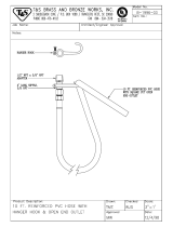
27 72661A Wand Holder 1
28 72662A Screw, #10 , Phil Flat SM, Black, Undercut Head 3
29 PX6+ 1/4 x 1/4 Female Quick Disconnect, Brass 1
30 7CX002 Nipple, Hex 1/4 MPT 2
31 X8239+ Washer, USS Flat Zinc 1
32 PC38+ Connector, Double Thread, Female, 1/4" to 1/4" Coupling 1
33 72642A Gasket, Vac Manifold, Circle 1
34 72625A Cover, Vacuum Manifold, Circle 1
35 72643A Pump Assembly, 500 PSI 1
36 72639A Gasket, Mounting Pressure Regulator 2
37 71644A Screw, #10 x 1”, Phil Pan, TS, Type A 18-8 SS 1
38 PF1750-2+ Heater Unit, 220V 1
39 72020A Screw, #12 x 1”, Self-Tap, PHMS, Zinc 4
4
0
7BS003 Screw, 1/4-20 x 1/2, Phil, Pan , MS 18-8 SS 4
41 X9014+ Hinge 2
42 PD8+ Strain Relief, 1/2" NPT 2
43 PX112+ Pigtail, Black, 12/3 SJT x 39" Long 1
44 PX112R+ Pigtail, Red, 12/3 SJT x 39" Long 1
45 X9131+ Cord Panel 1
46 X8008N+ Nut, Lock, 1/2" Steel Conduit 2
47 X9177+ Screw, Phil Pan, Ext Tooth Washer, Fully Threaded 2
48 72665A Insert, Tee Nut, ?-20 Thread, ? High, .305 Barrel Diameter 2
49 X8256+ Nut, 8-32 Keps, Zinc 4
50 7BS002 Screw, 8-32 x 1/2 Phil, Pan MS, 18-8 SS 4
51 7GF033 Pad, Motor Mount 2
53 X8848+ Jacknut, 1/4-20, Steel, #8 LJN 4
54 7EW001 Screw, 1/4-20 x 3/4", Phil, Pan, MS SS 4
55 X8235+ Washer, 1/4 Flat, USS, Zinc 4
56 71521A Tee, Barb, 1/2" x 1/2" x 1/2" 1
57 7DL008 Clamp, 1/2" Worm Gear, SS, Hex Slot 5
58 70079C Hose, 1/2" Wire Reinforced 42”
59 X9098+ Screw, #10 x 1”, A point, PH pan head 2
60 X9178+ Foam, Cord Panel 1
61 X8542+ Hose, Solution, 1/4" ID, 400 PSI 70”
62 PC66+ Fitting, Brass, 1/8 NPTM x 1/4 Hose Barb 5
63 71130A Coupler, QD, 1/8 M 2
64 70101A Nipple, QD, 1/8 F, Brass 2
65
72713B
Heater coil, 3-Stage V
acuum 1
66 7AT003 Barb, Hose, 1/4 H – ? M 2
67 SW158+ Cable Clamp 2
68 X8244+ Screw, 10-24 x 2”, Phil, Pan MS, Zinc 2
69
7AV001 Tee Union, 1/4 NPT 1
70
72726A
V
alve, 3-Way 1
71 PX212+ Fitting, Brass, 90° Elbow, 1/4 NPTM x 1/4 Hose Barb 1
72 7DL003 Clamp, Hose, 1/4" 7

A Tacony Company
3101 Wichita Court • Ft. W
orth, TX 76140-1710
WARRANTY
The manufacturer warrants to the original purchaser that products manufactured are free from defects of
workmanship and material, provided such goods are installed, operated and maintained in accordance with
written manuals or other instructions for a period of 5 years from date of purchase on housings and frame, 3
years on heater, 1 year on pump, vac motor, and parts and workmanship. In case you as our customer, meet
any trouble with your machine, contact your Powr-Flite representative who will be happy to be of service to
you and will take care of the warranty settlement.
NOTE: Alterations and changes made to the machine without written approval of the
manufacturer and use of unapproved spare parts will not be covered by warranty.
/