Page is loading ...

System 91 Manual
TC-9102
Technical Bulletin
Issue Date 0698
© 1998 Johnson Controls, Inc.
1
Order No. MN-9100-2117
Introduction Page 3
•
Model Types 4
•
Controller Functions 5
•
Output Types 10
•
Fan Output Types 12
Installation 15
•
Mounting 15
•
Wiring 16
•
Jumper and Switch Selections 22
•
Startup 23
•
Commissioning 23
Specifications & Technical Data 25
•
Factory-Set Parameters 26
•
Parameters for Supervisory System 27
•
Ordering Codes 28
TC-9102 Fan Coil Unit Controller

2 Technical Bulletin—TC-9102

Technical Bulletin—TC-9102 3
Introduction
The TC-9102 series of microprocessor-based controllers is designed for
the control of Fan Coil Units (FCUs) with heating and cooling, and a
single-speed, 3-speed or variable-speed fan. The controller can regulate
water valves, one or 2-stage electric heating, or a cooling unit where the
compressor has its own short cycle protection.
The comfort temperature set point of the controller may be adjusted via a
TM-9100 Series Room Command Module, and the occupied and
unoccupied control modes of operation temporarily changed. A window
open sensing contact may be connected to switch the controller to the off
mode, and a low temperature limit protection feature is available.
The controller is factory-configured to control with default operating
parameters so that no external setup devices are necessary. However, a
software package for a PC is available to verify the correct operation of
the controller and to modify the configuration, if necessary.
Winter and summer compensation may be enabled when the controller
receives outdoor air temperature data via the communications bus, and
modes of operation may be set by time scheduling programs or control
processes in the supervisory system.
2357 2664
Figure 1: TC-9102 Controller Figure 2: TM-9160 Room
Command Module

4 Technical Bulletin—TC-9102
2333
Figure 3: TM-9180 Room Command Module
The TC-9102 Controller is available in several model types according to
the type of outputs and the range of the integrated or remote set point
input. Refer to Ordering Codes at the end of this bulletin for details.
Model Types

Technical Bulletin—TC-9102 5
The controller can be connected to a Room Command Module, from
which it receives the room temperature, the remote set point and other
override signals. The TM-9180 intelligent Room Command Module
provides these signals via a serial bus connection to the controller. The
other Room Command Modules (TM-9150/9160/9170) provide the
signals as individually connected physical inputs to the controller. In
addition, an NTC temperature sensor is available for mounting within the
FCU.
For installations without a Room Command Module, the controller is
available with an integrated set point adjuster. Alternatively, the remote
set point and fan override controls may be incorporated into a custom
FCU control panel. Refer to the Specifications and Technical Data
section of this bulletin for details of the components required.
Occupancy Sensor
Window Contact
Room Temp.*
Remote Setpoint
Occupancy Button
Fan Override
(3-speed only)
Output Heating
Output Cooling
Fan Control
Controller
Room
Command
Module
Communications Bus
(Supervisory Control,
Outdoor Air Temp.)
NTC sensor may be
mounted in FCU.
*
tc2cwrcm
Figure 4: Controller with Room Command Module
Occupancy Sensor
Window Contact
Room Temp.
NTC Sensor
Fan Override
(3-speed only)
Output Heating
Output Cooling
Fan Control
Controller
(Setpoint)
Communications Bus
(Supervisory Control,
Outdoor Air Temp.)
tc2cwspa
Figure 5: Controller with Integrated Setpoint Adjuster
Controller
Functions

6 Technical Bulletin—TC-9102
The controller operates in standalone mode when it is not connected to a
supervisory system via the communications bus nor to a TM-9180 Room
Command Module. In standalone mode the controller may operate in one
of three control modes:
•
COMFORT (occupied): control at comfort set point
•
STANDBY (unoccupied): control at a standby level set point
•
OFF (not in use): low limit control only
The control modes are set by the window contact and occupancy sensor
inputs, and may be modified by the occupancy button on the Room
Command Module as shown in Table 1.
Table 1: Standalone Modes
WINDOW CONTACT OCCUPANCY SENSOR CONTROL MODE ALTERNATE MODE
(OCCUPANCY BUTTON)
WINDOW OPEN NO ACTION OFF NO ACTION
WINDOW CLOSED OCCUPIED COMFORT STANDBY
UNOCCUPIED STANDBY COMFORT
When connected to a supervisory system via the communications bus or
to a TM-9180 Room Command Module, the controller may operate in
COMFORT, STANDBY or OFF control modes, and additionally in
NIGHT mode:
NIGHT (scheduled unoccupied): control at a night level set point.
The control modes are set by the supervisory system or TM-9180, and are
modified by the occupancy sensor input and occupancy button on the
Room Command Module as shown in Table 2. The window contact input
always switches the controller to OFF control mode, and a MANUAL
mode is available from the supervisory system to inhibit the action of the
occupancy sensor and occupancy button.
Table 2: Supervisory Modes
WINDOW
CONTACT
SUPERVISORY
MODE
OCCUPANCY
SENSOR
CONTROL MODE ALTERNATE MODE
(OCCUPANCY BUTTON)
OPEN ANY MODE NO ACTION OFF NO ACTION
OFF OCCUPIED OFF OFF
UNOCCUPIED OFF OFF
NIGHT OCCUPIED NIGHT COMFORT (T)*
UNOCCUPIED NIGHT COMFORT (T)*
STANDBY OCCUPIED STANDBY COMFORT
CLOSED UNOCCUPIED STANDBY COMFORT (T)*
COMFORT OCCUPIED COMFORT STANDBY
UNOCCUPIED STANDBY COMFORT
OFF/MANUAL OFF
NIGHT/MANUAL NO ACTION NIGHT NO ACTION
STANDBY/MANUAL STANDBY
COMFORT/MANUAL COMFORT
*(T) = Timed (Returns to Control Mode after 1 hour.)
Standalone
Mode
Supervisory
Mode

Technical Bulletin—TC-9102 7
The set point in all control modes may be modified from the integrated
set point adjuster or from the remote set point dial/control panel on the
Room Command Module, according to the controller model type. The
controller models with a remote set point of 12-28°C require that a Room
Command Module or an external potentiometer is connected to give the
set point. Controllers with a remote set point of +/-3 K have internal
factory set points of 20°C for heating and 22°C for cooling.
The set point is decreased or increased in the STANDBY control mode
by the factory-set “Standby Bias Heating” and “Standby Bias Cooling”
values to reduce the heating or cooling energy required when the room is
temporarily unoccupied.
When a supervisory system is connected, the set point can be further
decreased or increased in the NIGHT control mode to further reduce
energy requirements during scheduled unoccupied periods such as nights,
weekends and holidays.
In the controller there are two “comfort” set points (Comfort Set Point
Heating and Comfort Set Point Cooling), and the difference between
these two values determines the zero energy band where neither heating
nor cooling is required. The controller calculates two working set points
(WSP Heating and WSP Cooling), which are the sum of the comfort set
point values, the “Remote Set Point” value coming from the integrated
set point adjuster or the Room Command Module, and the “Common Set
Point” value. In the supervisory mode an adjustment may be made to the
working set points either by changing the “Comfort Set Points,” or by
changing the value in the “Common Set Point” parameter of the
controller which enables the supervisory system operator to adjust the
setpoints for heating and cooling at the same time without affecting the
zero energy band. In summary:
Working Set Point (Heating) = Comfort Set Point (Heating) (Supervisory System)
+ Remote Set Point (integrated adjuster or Command Module dial)
+ Common Set Point (Supervisory System)
+ STANDBY or NIGHT Bias Heating (if mode is active)
Working Set Point (Cooling) = Comfort Set Point (Cooling) (Supervisory System)
+ Remote Set Point (integrated adjuster or Command Module dial)
+ Common Set Point (Supervisory System)
+ STANDBY or NIGHT Bias Cooling (if mode is active)
When the room temperature is below the working set point for heating,
the heating output increases according to the proportional band and
integral time parameters set for the heating control loop. When the room
temperature is above the working set point for cooling, the cooling output
increases according to the proportional band and integral time parameters
set for the cooling control loop. Heating and cooling control is illustrated
in figures 8 and 9.
Controller Set
Points

8 Technical Bulletin—TC-9102
When pressed for about one second, the occupancy button on the Room
Command Module changes the mode of operation of the controller to the
“Alternate Mode” or back to the normal “Control Mode” as shown in
Table 2. The “COMFORT (T)” alternate mode is active only for a period
of one hour, after which the controller reverts to the normal control
mode.
The controllers with on/off fan control switch the fan on when the room
temperature is below the working set point for heating and above the
working set point for cooling, and switch the fan off when the room
temperature has entered the zero energy band by the value set for the fan
differential. The fan can optionally be set to continue running in the zero
energy band in the COMFORT (occupied) mode, using the software
commissioning tool.
In controllers with 3-speed fan control outputs, the fan stages are
switched in sequence as the room temperature decreases or increases, and
Speed 1 remains on in the zero energy band.
In controllers with a 0 to 10 VDC output for a fan speed controller, the
output increases as the room temperature falls below the working set
point for heating or rises above the working set point for cooling, and
maintains a minimum output (set by default at 50%) when the room
temperature has entered the zero energy band.
For all controllers, in OFF mode the fan is switched off and the heating
and cooling outputs are set to the fully closed or off level. Fan control
sequences are shown in figures 10, 11 and 12.
3-Speed Fan Override
The speed of a 3-speed fan may be set manually from the Room
Command Module when the controller is in COMFORT (occupied)
mode. In the “AUTO” position the speed is set by the controller
according to the room temperature. In the manual “OFF-1-2-3” positions
the fan runs at the selected speed. The fan override is not active in
STANDBY, NIGHT or OFF modes.
In controller models with 2-stage on/off heating and cooling outputs, all
outputs are switched off when the fan speed is set to “OFF” to protect
electrical heating and cooling devices that require a minimum air flow for
normal operation. This feature can be enabled for other types of outputs,
if required, using the software commissioning tool. Refer to
Commissioning later in this document.
Low Limit Mode
The low limit mode is active when the room temperature falls below the
low limit set point. The fan is switched on at full speed and the heating
output is set to the maximum level until the room temperature rises by the
low limit differential value.
Alternate Mode
Fan Control

Technical Bulletin—TC-9102 9
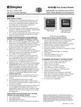
When the controller is connected to a supervisory system, the winter
and/or summer compensation modes may be enabled. The supervisory
system must be programmed to set the outdoor air temperature via the
communications bus on a periodic basis. After a power interruption the
winter and summer compensation modes are temporarily disabled until a
new outdoor air temperature value is received. When the outdoor
temperature falls below the winter set point, the working set point of the
controller will be raised or lowered in accordance with the winter
authority slope. When the outdoor temperature rises above the summer
set point the working set point of the controller will be raised in
accordance with the summer authority slope. The maximum amount of
compensation is limited by the Winter Authority Limit and the Summer
Authority Limit.
The effect of the winter and summer compensation on the controller set
point is shown below.
0
-5
-4
-3
-2
-10
1
2
3
4
5
-20-30
0
-1
10 20
30
40 50
Winter Authority Slope
(+0,1)
Winter Authority
Limit (-3 K))
Winter
Setpoint
(10°C)
Summer
Setpoint
(24°C)
Summer Authority Limit
(+5 K)
Summer Authority
Slope (+0,2)
Setpoint
Compensation
(K)
Outdoor Air
Temperature
(°C)
Winter Authority
Slope (-0,1)
tc2winsu.drw
Figure 6: Winter/Summer Compensation
Winter/Summer
Compensation

10 Technical Bulletin—TC-9102
When the controller is connected to a remote N2 Bus and supervised by a
Metasys N2 Dialer (NU-NDM101-0) which is linked to a Metasys
network by a telephone line, the following alarm conditions in the
controller will initiate the automatic dial feature:
•
Window Open
•
Low Limit mode
•
High or low alarm limit violation of the room temperature when alarm
limits have been set by the supervisory system.
When any one of these alarm conditions occurs, the N2 Dialer will detect
the alarm and connect the remote N2 Bus to the Metasys network. When
the telephone line connection is established the controller alarm status
will automatically be reset and the controller is then ready to report
further alarm conditions as they occur. Refer to the Technical Bulletin of
the NU-NDM101-0 for further information.
The heating and cooling outputs are one of the following types,
depending on the controller model code:
The output is an analog voltage between 0 and 10 VDC in direct
proportion to the controller output from 0 to 100%.
The DAT output is a triac which is switched on for a duration within the
set heating or cooling valve cycle time in direct proportion to the
controller output from 0 to 100%. To avoid unnecessary switching of the
valve actuator when the output is between 0 and 5% the triac remains off,
and when the output is between 95 and 100% the triac remains on. The
default cycle time is 300 seconds.
OFF
ON
50% Output
30% Output
DAT C
y
cle Time
DAT C
y
cle Time
Figure 7: DAT Output
Auto-dial
Feature
Output Types
0 - 10 VDC
DAT - Duration
Adjust Type

Technical Bulletin—TC-9102 11
The PAT output is a pair of triacs which are switched on to open and
close an incrementally driven heating or cooling valve. The duration of
switching is directly proportional to the change in the controller output
and related to the full stroke time of the valve such that a 100% change
will completely open or close the valve. At the 0% or 100% position the
duration of switching is increased to ensure that the valve is completely at
its end position and the appropriate triac is switched on for the full stroke
time every two hours to ensure that the valve remains at its end position.
To prevent unnecessary wear on the actuator, the triac output will only be
switched when the output change exceeds 1% in the same direction as the
previous change or 2% if the direction of change is reversed. The default
full stroke time is 60 seconds.
100
0
5
10 30
Output (%)
Room
Temperature (°C)
Heating
Cooling
12 14 16 18 20 22 24 26
Night
Standby
Comfort
Comfort
Standby
Night
Low Limit
tc2hcvdc
Figure 8: Heating/Cooling Control 0-10 VDC, DAT, PAT
The output is a pair of triacs which are switched on in sequence as the
controller output increases. The first stage triac is switched as soon as the
output is above 0% and the second stage triac is switched when the output
is equal to the set load rating for the first stage which is defaulted to 50%.
The switching differential is fixed at 5%. When this type of output is used
with 3-speed fan control, the output will be switched off whenever the
fan speed is manually overridden to the “OFF” position on the Room
Control Module. The control diagram is shown below.
Night
Standby
0
Room
Temperature
(
°C
)
Heating
Coolin
g
100
Output (%)
1
222 222
1
1
111
Comfort
Comfort
Standby
Night
Low Limit
5
10
30
12 14 16 18 20 22 24 26
Figure 9: Heating/Cooling Control - 2-Stage On/Off
PAT - Position
Adjust Type
2-Stage On/Off

12 Technical Bulletin—TC-9102
The output is a normally open relay contact which closes when the fan is
required to run. Terminals are provided to connect the fan supply voltage
to the controller in order to facilitate the wiring to the fan motor. The fan
supply voltage is not used within the controller.
OFF
ON
5
10 30
Room
Temperature (°C)
12 14 16 18 20 22 24 26
Low Limit
Night
Standby
Standby
Night
Comfort
Figure 10: On/Off Fan Control - Switch Points
The output is a set of interlocked relay contacts, one contact for each
speed which closes when that speed is selected to run. Terminals are
provided to connect the fan supply voltage to the controller in order to
facilitate the wiring to the fan motor. The fan supply voltage is not used
within the controller.
5
10 30
Room
Temperature (°C)
Low Limit
12 14 16 18 20 22 24 26
1
2
3
1
22
3
3
Night
Standby
Comfort
Comfort
Standby
Night
tc2swpts
Figure 11: 3-Speed Fan Control - Switch Points
Fan Output
Types
Fan On/Off
3-Speed Fan
Control

Technical Bulletin—TC-9102 13
The output is a control signal for driving a fan speed controller with an
opto-isolated 0 to 10 VDC input. As the output voltage increases, the fan
speed controller must increase the speed of the fan from the minimum
speed of the fan motor to its maximum speed. When the output is below
the voltage required for the minimum speed, the fan must be switched
off.
100
0
5
10 30
Output (%)
Room
Temperature (°C)
Heating
Cooling
12 14 16 18 20 22 24 26
Minimum
Speed Level
Night
Standby
Comfort
Comfort
Standby
Night
Low Limit
tc2facos
Figure 12: 0 to 10 VDC Fan Control Signal
0 to 10 VDC
Control Signal

14 Technical Bulletin—TC-9102

Technical Bulletin—TC-9102 15
Installation
The TC-9102 series controller is designed to be mounted within the Fan
Coil Unit housing or within a control cabinet. The mounting location
must be clean and dry, and not subject to extreme heat or cold. The
installation and electrical wiring must conform to local codes and should
be carried out by authorized personnel only. Users should ensure that all
Johnson Controls' products are used safely and without risk to health or
property.
For surface mounting, slide the two mounting brackets into the slots at
opposite corners of the controller base behind the terminals. Fix to the
surface using the 4-mm diameter self-tapping screws.
For DIN rail mounting, place the controller on the upper edge of the rail
and press the controller firmly against the rail until the spring-loaded clip
engages the lower edge of the rail. To remove the controller, insert a
screw driver into the clip at the base of the controller and pull the clip
downwards to release. Alternatively, lift the controller upwards against
the spring of the retaining clip and pull forward from the top.
Figure 13: TC-9102 Controller Dimensions
Mounting
itc02dim
6 mm/
0.24"
120 mm/4.72"
118 mm/
4.64"
108 mm/4.25"
3
31 mm/
1.22"
4.6 mm/
0.18"
101.6 mm/
3.99"
14 mm/
0.55"
14 mm/
0.55"
(Separable Terminals
Only)

16 Technical Bulletin—TC-9102
Note: A minimum of 25 mm of space is required above and below the
controller for the removal of separable terminals.

Technical Bulletin—TC-9102 17
Before connecting or disconnecting any wires, ensure that all power
supplies have been switched off and all wires are potential-free to prevent
equipment damage and avoid electrical shock.
Terminations are made on the terminal blocks, at the top and bottom of
the controller, which accept up to 1.5mm
2
wires. Follow the wiring
diagrams shown in figures 14 to 20.
When the TC-9102 model with separable terminal blocks is being wired,
it is recommended that the removable parts of the blocks be unplugged
before terminating the wires, and that they are not plugged in again until
the wiring has been fully checked.
Separate extra low voltage (safe) wiring from power line voltage wiring.
A distinctive colour such as white or pink is recommended for low
voltage wiring. Keep all cables as short as possible and tie in position. Do
not run cables close to transformers or high frequency generating
equipment.
The 24 V supply must be stable and not shared with other switched
inductive loads. When multiple loads are connected to one transformer,
wire each load from the transformer separately so that any possible
disturbances from one load will have minimal effect on other loads.
Complete and verify all wiring connections before continuing with the
installation procedure.
!
CAUTION: Connections to the on/off or 3-speed fan control
terminals may carry up to 250 VAC. Isolate live and
neutral supply lines (double-pole switch) before
servicing.
Wiring

18 Technical Bulletin—TC-9102
tc2onoff
External supply for fan
230 VAC L = Live
Isolate before servicing.
Analog
Common
Digital Common
Window
Contact
Occupancy
Sensor
Mode LED
NTC
Sensor
Analog 0 -10 VDC
PAT 24 VAC
24 VAC
Common
Ground
24 VAC
Supply
DAT 24 VAC
ON-OFF
(2 stages)
24 VAC
+
Remote
Set Point
Fan
ON-OFF
_
N
L
11 12 1310 14 15 20 21 22 23 24
42 41
40 32 31 30 123
61 60
71 70
1
2
M
Analog InputsDigital Inputs
System 91 N2
Communication Bus
Cooling Output Heating Output
Power Supply
RT+
RT- COM
SHIELD
+
-
When using multistranded wire,
crimp a metal sleeve over the exposed
conductors before inserting into
terminals 60...71.
See Note 1
See Note 2
See Note 3
Note 1: For PAT, DAT and ON-OFF outputs, terminals 1, 31 and 41 are
internally connected.
For 0-10 VDC outputs, terminals 30 and 40 are internally connected
.
Note 2: Wiring for Cooling Output is the same as shown for Heating Output.
Note 3: See also figures 17-20 for Room Command Module Wiring.
Figure 14: TC-9102 Controller Wiring - On/Off Fan Control

Technical Bulletin—TC-9102 19
tc2wir3s
3-Speed
External supply for fan
230 VAC L = Live
Isolate before servicing.
Window
Contact
Mode LED
NTC
Sensor
Analog 0 -10 VDC
PAT 24 VAC
+
M
24 VAC
Common
Ground
24 VAC
Supply
DAT 24 VAC
ON-OFF
(2 stages)
24 VAC
+
Remote
Set Point
-
N
L
Fan
Low Med.
High
Fan Control
Override
2
1
63 6271 70 61 60 42
41
40
32
31
30
3 2 1
11 12 1310 14 15 20 21 22 23 24 50
51
52
Power Supply
Cooling Output
Heating Output
Occupancy
Sensor
Digital Inputs
Analog Inputs
System 91 N2
Communication Bus
Digital Common
Analog
RT+
RT-
COM
Common
SHIELD
-
When using multistranded wire,
crimp a metal sleeve over the exposed
conductors before inserting into
terminals 60...71.
See Note 1
See Note 2
See Note 3
Note 1: For PAT, DAT and ON-OFF outputs, terminals 1, 31 and 41 are
internally connected.
For 0-10 VDC outputs, terminals 30 and 40 are internally connected.
Note 2: Wiring for Cooling Output is the same as shown for Heating Output.
Note 3: See also figures 17-20 for Room Command Module Wiring.
Figure 15: TC-9102 Controller Wiring - 3-Speed Fan Control

20 Technical Bulletin—TC-9102
Note 1: For PAT, DAT and ON-OFF outputs, terminals 1, 31 and 41 are
internally connected.
For 0-10 VDC outputs, terminals 30, 40 and 60 are internally
connected.
Note 2: Wiring for Cooling Output is the same as shown for Heating Output.
Note 3: See also figures 17-20 for Room Command Module Wiring.
12
Window
Contact
Occupancy
Sensor
Mode LED
NTC
Sensor
Analog 0 -10 VDC
PAT 24 VAC
M
24 VAC
Common
Ground
24 VAC
Supply
DAT 24 VAC
ON-OFF
(2 stages)
24 VAC
61
0 -10 VDC
Fan Speed Control
Remote
Set Point
-
1
2
+
-
11
42
12 1310 14 15 20
21 22
23
24
4160
40 32 31 30
3
+
RT- COM SHIELDRT+
Digital Inputs
Analog Inputs
System 91 N2
Communication Bus
tc2wivdc
Cooling Output
Heating Output
Power Supply
Digital Common
Analog
Common
+
-
See Note 1
See Note 2
See Note 3
1/34