Danfoss 180B3032 Installation guide

Type
Installation guide
ro-solutions.com
Instruction
APP pump instruction
APP 0.6-1.0, APP 1.5-2.5 and
APP 3.0-3.5
Instruction
APP pumps
APP 0.6-1.0 / APP 1.5-2.5 / APP 3.0-3.5
hpp.danfoss.com
Instruction | APP pump instruction APP 0.6-1.0, APP 1.5-2.5 and APP 3.0-3.5
2
180R9065 | 521B0733 | DKCFN.PI.013.C9.02 | 11.2019
1. Identification ...........................................................................3
2. System design ..........................................................................3
2.1 Open-ended systems with water supply from a tank . . . . . . . . . . . . . . . . . . . . . . . . . . . . . . . . . . . . .3
2.2 Open-ended systems with direct water supply...........................................3
2.3 Problems with reversing pumps . . . . . . . . . . . . . . . . . . . . . . . . . . . . . . . . . . . . . . . . . . . . . . . . . . . . . . . . .3
2.4 General guidelines for calculation of pressure losses .....................................4
2.5 General comments on...................................................................4
3. Building up the pump unit ..............................................................5
3.1 Mounting ...............................................................................5
3.2 Direction of rotation ....................................................................5
3.3 Orientation .............................................................................6
3.4 Protection from too high pressures ......................................................6
3.5 Connections ............................................................................6
4. Initial start-up...........................................................................7
5. Operation...............................................................................7
5.1 Temperature ............................................................................7
5.2 Pressure ................................................................................7
5.3 Dry running.............................................................................7
5.4 Disconnection ..........................................................................7
5.5 Storage .................................................................................7
5.5.1 Open-ended systems with water supply from tank.......................................7
5.5.2 Open-ended systems with direct water supply...........................................8
6. Service..................................................................................8
6.1 Periodic maintenance . . . . . . . . . . . . . . . . . . . . . . . . . . . . . . . . . . . . . . . . . . . . . . . . . . . . . . . . . . . . . . . . . . .8
6.2 Repair ..................................................................................8
Table of Contents
Instruction | APP pump instruction APP 0.6-1.0, APP 1.5-2.5 and APP 3.0-3.5
3
180R9065 | 521B0733 | DKCFN.PI.013.C9.02 | 11.2019
The design of the system must ensure that self
emptying of the pump during standstill is
avoided.
The inlet pressure of the pump must never
exceed the outlet pressure. This may typically
occur in boosted or open-ended systems with
direct water supply.
In order to avoid this it is recommended to install
a pre-stressed check valve or a pressure switch in
the pump inlet.
The opening pressure of the check valve must be
bigger or equal to the inlet pressure.
2.1 Open-ended systems with water supply
from a tank
(The numbers 1-3 refer to the drawing below.)
In order to eliminate the risk of cavitation,
observe the following guidelines:
1) Place the tank above the pump (water level
in the tank should always be above the
pump).
2) Place the inlet lter before the tank.
3) Dimension the inlet line to obtain mini-
mum pressure loss (large ow area,
minimum pipe length, minimum number
of bends/connections, ttings with small
pressure losses).
1. Identification
2. System design 2.2 Open-ended systems with direct water
supply
The pump is supplied with water direct from a
booster pump.
The water pressure must not exceed 5 barg
(72.5 psig).
2.3 Problems with reversing pumps
If exposed to high pressure in the outlet while
the electric motor is not energized, the pumps
will start spinning backwards. This will not harm
the pumps as long as the pressure in the inlet
does not exceed the max. pressure of 5 barg.
If a non-return valve is mounted in the inlet line,
a low-pressure relief valve will also be required.
Alternatively a high-pressure check valve could
be mounted in the pump discharge line to
prevent the pump from reversing.
The dotted setup ensures that the inlet pressure
does not exceed the 5 barg, when a non- return
valve is mounted in the inlet.
5 barg
[72.5 psig]
PUMP
Type APP 0.6
Code no. 180BXXXX
Serial no. XXXXXX02-XXX
MADE IN DENMARK
Danfoss A/S, 6430 Nordborg, Denmark
Instruction | APP pump instruction APP 0.6-1.0, APP 1.5-2.5 and APP 3.0-3.5
4
180R9065 | 521B0733 | DKCFN.PI.013.C9.02 | 11.2019
2.4 General guidelines for calculation of
pressure losses
In order to avoid the risk of cavitation, the inlet
pressure at the pump must be in accordance
with the specifications mentioned in Data
sheet (521B1331).
The inlet line connection must be properly
tightened, as possible entrance of air will cause
cavitation.
The suction conditions can be optimized
according to below guidelines.
2.5 General comments on
Filtration
A good filtration is vital to ensure a long and
trouble free life of the pump.
When selecting a lter or strainer, please note
that lter materials should be compatible with
water, i.e. should neither corrode or dissolve. Also
be aware of the electrochemical series of the
applied materials.
Main lter must have a neness of 10 μm abs.
ß
10
≥ 5000. The pressure loss across the lter
should be monitored.
Water tank
Must be made of corrosion-proof material such
as stainless steel or plastic and must be sealed to
prevent entrance of impurities from the environ-
ment.
In smooth pipes and hoses
In 90° bends
In smooth pipes and hoses
Instruction | APP pump instruction APP 0.6-1.0, APP 1.5-2.5 and APP 3.0-3.5
5
180R9065 | 521B0733 | DKCFN.PI.013.C9.02 | 11.2019
3. Building up the pump
unit
Automatic pressure equalization between tank
and surroundings must be ensured.
Inlet from the water supply and inlet to the
pump should be placed in opposite ends of the
tank to calm and deaerate the water, and to
ensure optimum opportunity for particles to
settle.
Pump suction line should be placed relatively
high above the tank bottom in order to prevent
settled particles from being led into the pump.
We recommend a separation (“wall”) to separate
the inlet from the outlet end of the tank.
Monitoring
It is recommended to continuously monitor the
following conditions:
Water level in the tank
Filter contamination
Pressure (inlet- and outlet side of the
pump)
3.1 Mounting
(Please also see hints in “Right and Wrong”)
If alternative mounting is desired, please contact
the Danfoss High Pressure Pumps.
Choose proper tolerances to ensure an easy
mounting of the elastic coupling without use of
tools.
Please take care to observe the recommended
length tolerances of the chosen coupling, as an
axial force on the pump will damage the pump.
3.2 Direction of rotation
Is indicated by an arrow at the pump label.
max. 0.25 mm
max. 0.01 inch
3-5 mm
[0.12-0.2 inch]
A Elastic coupling
B Bell housing
C Motor shaft
Instruction | APP pump instruction APP 0.6-1.0, APP 1.5-2.5 and APP 3.0-3.5
6
180R9065 | 521B0733 | DKCFN.PI.013.C9.02 | 11.2019
3.3 Orientation
The pump can be mounted/oriented in any
horizontal direction. Vertically only with the shaft
pointing upwards.
3.4 Protection from too high pressures
The pump should be protected against too high
pressure by means of a pressure relief valve or a
bypass/unloading valve placed on the pressure
side.
The valve should be placed as close to the pump
as possible. The opening characteristics of the
valve must not result in peak pressures higher
than 200 barg (2900 psig).
The valve outlet must not be connected
directly to the pump suction line. It shall be
connected directly to the tank.
3.5 Connections
APP 0.6-1.0 APP 1.5-2.5 and APP 3.0-3.5
O I O I C
Thread size G 1/2 × 13 G 1/2 × 13 G 3/4 x 16 G 3/4 × 16 M6 Hexagon
5 mm key
Max tighten
torque
65 Nm
48 (lbf ft)
65 Nm
48 (lbf ft)
90 Nm
66 (lbf ft)
90 Nm
66 (lbf ft)
5 Nm
3.5 (lbf ft)
Contact your ttings supplier for tightening torque requirements. Recommended torque values refer to steel
washers containing a rubber sealing element.
O
C
C
I
D
O Outlet
I Inlet
C Bleed
D Parallel key 5 × 5 × 20,
DIN 6885
P Pressure
T Tank
Instruction | APP pump instruction APP 0.6-1.0, APP 1.5-2.5 and APP 3.0-3.5
7
180R9065 | 521B0733 | DKCFN.PI.013.C9.02 | 11.2019
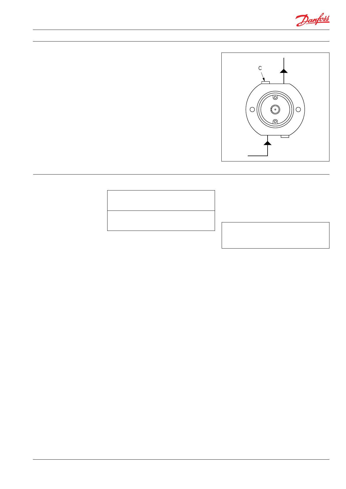
Before start-up, loosen the top bleeding plug “C”,
except for APP 0.6 - 1.0. When water appears
from the bleeding plug, retighten the plug. With
its inlet line connected to the water supply or the
tank, the pump is now started with open outlet
port.
At the initial start of the system, the pump
should be run without pressure for about
5 minutes, thus removing possible impurities
from pipes, hoses, etc. However, the system
should be ushed before start-up – without the
connected pump.
WARNING:
Make sure that the direction of rotation of the
electric motor corresponds to the direction of
rotation of the pump. Otherwise the pump will
be damaged if a check valve is placed between
pump and tank.
4. Initial start-up
5. Operation 5.1 Temperature
In case of lower operating temperatures, please
contact Danfoss High Pressure Pumps.
5.2 Pressure
The inlet pressure must be min. 0.5 barg
(7.25 psig) and max. 5 barg (72.5 psig). At lower
pressures the pump will cavitate, resulting in
damage to the pump.
Max. pressure on the pump’s outlet line should
be limited at 80 barg (1160 psig) continuously.
Short-term pressure peaks (e.g. in connection
with closing of a valve) of up to 100 barg
(1450 psig) are acceptable.
NB:
The pump unit should include a pressure
gauge on the high pressure side.
5.3 Dry running
When running, the pump must always be
connected to the water supply in order to avoid
damage if it should run dry.
In systems with water tank it is recommended to
build in a level gauge in the tank to avoid the risk
of running dry.
5.4 Disconnection
If the inlet line is disconnected from the water
supply, the pump will be emptied of water
through the disconnected inlet line.
When starting up again, follow the bleeding
procedure described under section 4: Initial start
up.
5.5 Storage
Frost protection:
When preparing the pump for long-term storage
or for temperatures below the freezing point,
ush the pump with an anti-freeze medium type
monopropylene glycol to prevent internal
corrosion or frost in the pump.
For further information on anti-freeze media,
please contact Danfoss High Pressure Pumps.
Recommended procedure:
5.5.1 Open-ended systems with water supply
from tank
1. Empty the tank of water and empty the
pump housing through the lower bleeding
plug. When the pump is empty, retighten
the plug.
2. Through the upper bleeding plug, ll the
pump housing with anti-freeze medium.
Pour anti-freeze medium into the tank.
Connect a hose to the outlet of the pump
and lead the other end of the hose back to
tank.
3. Quickly start and stop the pump. Make sure
that the pump does not run dry. The pump
is now protected against internal corrosion
and frost.
Storage temperature:
Min. -40° C to max. +70° C
Min. -40° F to max. +158° F
C Bleeding plug
Fluid temperature:
Min. +2° C to max. +50° C
Min. +35.6° F to max. +122° F
Ambient temperature:
Min. +2° C to max. +50° C
Min. +35.6° F to max. +122° F
Danfoss A/S
High Pressure Pumps
Nordborgvej 81
DK-6430 Nordborg
Denmark
© Danfoss | DCS (im) | 2019.11
180R9065 | 521B0733 | DKCFN.PI.013.C9.02 | 8
6.1 Warranty
Danfoss APP pumps are designed for long
operation, low maintenance and reduced
lifecycle costs.
Provided that the pump has been running
according to the Danfoss specications, Danfoss
guarantees 8,000 hours service-free operation,
however, max. 18 months from date of produc-
tion. If Danfoss recommendations concerning
system-design are not followed, it will stongly
inuence the life of the APP pumps.
6.2 Maintenance
After 8,000 hours of operation, it is recom-
mended to inspect the pump and change any
worn parts, e.g. pistons.
This is done in order to prevent a potential
breakdown on the pump. If the parts are not
replaced, more frequent inspection is recom-
mended according to our guidelines.
Pump shutdown:
The APP pumps are made of Duplex/Super
Duplex materials with excellent corrosion
properties. It is however, always recommended
to ush the pump with fresh water when the
system is shut down.
When stopping the pump for more than 1 day,
ush the pump with permeate by rotating the
pump for 10 sec. Flushing through the ushing
valve of the pump without rotating the pump is
not enough for cleaning the inside of the pump.
The pump can be ushed with biocide like the
membranes. The biocide must be compatible
with the materials used in our pump (materials
can be found in the parts list in the Operating
Guide)
6.3 Repair
In case of irregular function of the APP pump,
please contact Danfoss High Pressure Pumps
sales organisation.
6. Service
5.5.2 Open-ended systems with direct water
supply
1. Disconnect the water supply to the pump.
2. Through the lower bleeding plug, empty
the pump housing of water and close it
again.
3. Connect the pump to a tank of e.g. 25 litre
(6 gal.) of anti-freeze additive. Connect a
hose to the inlet port of the pump and via
another hose return the ow from the
outlet port to the tank with anti-freeze
additives.
4. Quickly start and stop the pump. Make sure
that the pump does not run dry. The pump
is now protected against internal corrosion
and frost.
Storage:
Storage of the pump that have been in opera-
tion:
For shorter periods of storage ush the pump
with permeate rotating the pump for 10 sec.
empty permeate and store.
For long term storage (more than 2 months)
Danfoss recommends servicing the product and
clean any biological growth of the surfaces. Store
the pump dry without water inside.
  • Page 1 1
  • Page 2 2
  • Page 3 3
  • Page 4 4
  • Page 5 5
  • Page 6 6
  • Page 7 7
  • Page 8 8

Danfoss 180B3032 Installation guide

Type
Installation guide

Ask a question and I''ll find the answer in the document

Finding information in a document is now easier with AI