Page is loading ...

INSTRUCTION MANUAL
AFP12A (12volt / Automatic Nozzle) | AFP12M (12volt / Manual Nozzle)
AFP24A (24volt / Automatic Nozzle) | AFP24M (24volt / Manual Nozzle)
ELECTRIC DIESEL PUMP KIT
AFP12-im -issue4-2020

2macnaught | instruction manual
INSTRUCTION MANUAL
ELECTRIC DIESEL PUMP KIT
AFP12A (12volt / Automatic Nozzle) | AFP12M (12volt / Manual Nozzle)
AFP24A (24volt / Automatic Nozzle) | AFP24M (24volt / Manual Nozzle)
INTRODUCTION
Thank you for purchasing a Macnaught 12 or 24 volt
Electric Diesel Fuel Pump.
The Macnaught Electric Diesel Fuel Pump kit is
supplied, complete with either a Manual or Automatic
Fuel Nozzle, 2m x 3/4” Suction Hose, 4m x 3/4”
Delivery Hose and 4M power cable with fuse holder
and alligator clips.
This manual assists you in operating and maintaining
your electric diesel fuel pump. The information contained
will help ensure many years of dependable trouble free
operation.
GENERAL INFORMATION
ASSEMBLY
CAUTION
Use oil resistant pipe sealant or Teon® tape on all pipe
threads.
1. Fit the strainer supplied to the end of blue suction hose
and secure with the hose clamp supplied.
2. Fit the 3/4” hose tail to the remaining end of the suction
hose and secure with the hose clamp supplied.
3. Connect the suction hose assembly to the pump inlet
(refer to direction of ow on pump)
4. Connect the delivery hose to the outlet on the pump.
5. Fit the swivel to the delivery hose and t the nozzle
with the supplied swivel.
ONLY USE this pump with Diesel,
Failure to do so may cause personal injury or damage
the pump which voids pump warranty.
DESCRIPTION
This diesel transfer pump is designed to reliably transfer
diesel. The pump is a self priming, positive displacement,
rotary vane pump operating on either 12 or 24V DC
depending on the model. The pump will deliver up to 40
litres per minute, has a built-in bypass valve that keeps
the operating pressure below 1.3 Bar (18 psi) and the
motor has a 30 minute duty cycle
If you require a fuel lter or meter for your pump,
Macnaught recommends that you use the Macnaught
HA1S-01 fuel lter and/or select one of the Macnaught
fuel meters.
PUMP INSTALLATION
Please read and retain this instruction manual to assist
you in the operation and maintenance of this quality
product. If you require any further assistance please
contact your local Macnaught distributor.
WARNING
This pump must not be used in bypass mode (nozzle
closed) for more than 2 minutes other wise serious
damage to the motor will occur.
An inline fuse with the same rating to the one tted to
electric cable on this pump must tted and used at all
times otherwise pump warranty will be void.
Note:
The pump should be sheltered from rain and
weather events
This motor is not explosion proof

3
macnaught.com.au
INSTRUCTION MANUAL
ELECTRIC DIESEL PUMP KIT
AFP12A (12volt / Automatic Nozzle) | AFP12M (12volt / Manual Nozzle)
AFP24A (24volt / Automatic Nozzle) | AFP24M (24volt / Manual Nozzle)
1. Position the pump assembly securely.
NOTE: Ensure the pump is positioned to a secure
location.
2. Insert the suction hose with suction strainer tted into
the fuel tank.
NOTE: Tanks or barrels should be anchored to prevent
tipping in both the full and empty conditions.
OPERATION
NOTE: Avoid sparks that could cause a re:
DO NOT use a patch cord to extend the power cables.
DO NOT let the pump run dry for more than 2 minutes
or damage may occur
1. Before use, wipe off any dirt or moisture that may have
accumulated on the nozzle or hoses.
2. Insert nozzle into the container to be lled. Insert
suction hose (if applicable) into the diesel storage tank.
3. Switch the motor on.
MAINTENANCE
IMPORTANT
DO NOT modify any part of the unit or any warranty on
the product will be automatically void.
1. Inspect and clean the strainer on the suction bottom of
the hose / pipe regularly.
2. Always clean the battery terminals and clips before use
to ensure a good connection.
3. Always relieve the line pressure by opening the nozzle,
draining hose. Disconnect power before starting any
pump maintenance
4. Hoses should be inspected regularly.
(Replace if found to be cracked or worn)
5. The rotor and vanes will eventually wear. They should
be replaced if pump performance degrades.
(refer to trouble shooting guide)
3. Connect the battery clips power cord to a suitable
battery which is capable of delivering the necessary
voltage and current (see the Technical Data, back page
of this manual)
a) Attach the RED clip to the positive (+) battery terminal.
b) Attach the BLACK clip to the negative (-) battery
terminal or to the vehicle frame.
NOTE: Maximum suction distance no more than 2 meters
4. Operate the nozzle lever to dispense uid.
5. When the desired amount of uid has been dispensed,
release nozzle lever to stop ow.
6. Immediately switch motor off.
7. Nozzle and hoses should be kept clean and dry when
not in use.
NOTE: If the pump fails to prime, remove nozzle, turn
pump on to prime then re-t nozzle
Pump Model Fluid Flow Rate Power Supply Fuse Total Cable
Length
Minimum Wire Section
AFP12A/M
Diesel
40 LPM
12 VDC
30A
0 - 4 m 2.5 mm2 13 AWG
4 - 6 m 4 mm2 11 AWG
4 - 8 m 6 mm2 9 AWG
AFP24A/M
Diesel 40 LPM 12VDC 15A 0 - 4 m 2.5 mm2 13 AWG
4 - 8 m 4 mm2 11 AWG
AHFP85L-
12V
Diesel
85 LPM
12VDC
30A
0 - 4 m 6 mm2 9 AWG
4 - 6 m 10 mm2 7 AWG
6 - 10 m 16 mm2 5 AWG
Electric cable selection table (minimum requirement)

4macnaught | instruction manual
INSTRUCTION MANUAL
ELECTRIC DIESEL PUMP KIT
AFP12A (12volt / Automatic Nozzle) | AFP12M (12volt / Manual Nozzle)
AFP24A (24volt / Automatic Nozzle) | AFP24M (24volt / Manual Nozzle)
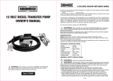
PARTS LIST
AVAILABLE ACCESSORIES
Manual nozzle
Automatic nozzle
Delivery hose
Telescopic suction tube with strainer - ATS205
For wet seal kit order AFP12-1K
For poppet valve set order AFP12-2K
1
2
3
4
5
6
7
8
9
10
11
12
13
11
Manual or Auto nozzle
Strainer
Suction hose
Delivery hose
Pump unit
Hose clamp
Hose tail
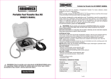
Item Description Qty
1 Pump Body 1
2Motor 1
3Base plate 1
4By pass cap 1
5By pass spring 1
6By pass value 1
7Pump seal 1
8O’ring 1
9Drive key 1
10 Rotor 1
11 Vane Set 5
12 Tie rod screws 2
13 Face plate screws 3
14 Switch 1
Switch
(14)
PARTS DIAGRAM

5
macnaught.com.au
INSTRUCTION MANUAL
ELECTRIC DIESEL PUMP KIT
AFP12A (12volt / Automatic Nozzle) | AFP12M (12volt / Manual Nozzle)
AFP24A (24volt / Automatic Nozzle) | AFP24M (24volt / Manual Nozzle)
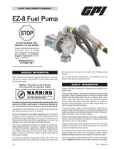
(Correct seal orientation)
(Correct vane and rotor orientation)
(Poppet valve assembly / dissassembly)
Push
Turn 90 Deg
Exit
PUMP DIMENSIONS

6macnaught | instruction manual
INSTRUCTION MANUAL
ELECTRIC DIESEL PUMP KIT
AFP12A (12volt / Automatic Nozzle) | AFP12M (12volt / Manual Nozzle)
AFP24A (24volt / Automatic Nozzle) | AFP24M (24volt / Manual Nozzle)
Problem Cause Solution
Pump fails to start 1) Suction hose/tube has a blockage 1) Clear blockage from suction hose/tube
2) Outlet is blocked 2) Check outlet hose and nozzle for blockage
and correct operation
3) Bypass poppet not closing 3) Check bypass valve is closing correctly
4) Vanes sticking 4) Check vanes are sliding freely in the slots
(remove burrs or replace vanes if required)
5) Excessive vane or rotor wear 5) Replace rotor and/or vanes
6) Leak from front o’ring 6) Check o’ring for correct sealing, replace if
required
Pump vibrates but does not turn on 1) Dirt jammed inside the pump 1) Clean pump chamber
2) Faulty motor 2) Replace pump
3) Broken drive key 3) Replace drive key
Low Flow 1) Blocked strainer 1) Clean or replace strainer
2) Restriction on the inlet or outlet 2) Incorrect size hoses used on inlet or outlet
3) Excessive rotor or vane wear 3) Replace worn or damaged components
4) By pass poppet blocked 4) Check poppet valve for correct operation
5) Low fluid level in tank 5) Fill tank
Motor overheating 1) Fluid too thick (viscous) 1) Fluid to be no thicker than Diesel
2) Motor running longer than 30 minutes 2) Pump must only run for 30 minutes before
cooling
3) Blocked suction hose 3) Clean blockage from suction hose
4) Blocked strainer 4) Clean strainer
Motor not turning on 1) Poor electrical connection 1) Clean terminals and battery clamps
2) Battery low or faulty 2) Check battery
3) Blown or faulty fuse 3) Check pump and/or replace fuse
4) Faulty switch 4) Replace switch
Pump leaking out of weep hole 1) Worn or damaged shaft seal 1) Replace seal
2) Fluid compatibility 2) Only use compatible fluid
TROUBLE SHOOTING GUIDE

7
macnaught.com.au
INSTRUCTION MANUAL
ELECTRIC DIESEL PUMP KIT
AFP12A (12volt / Automatic Nozzle) | AFP12M (12volt / Manual Nozzle)
AFP24A (24volt / Automatic Nozzle) | AFP24M (24volt / Manual Nozzle)
AFP12 AFP24
Maximum Flow 40ltr/min 40ltr/min
Maximum pressure 1.3bar 1.3bar
Voltage 12 Volt 24 Volt
Current 18 amp 12 amp
Duty cycle 30 min 30 min
Fuse 30 amp 15 amp
Inlet / Outlet 3/4” BSP (F) 3/4” BSP (F)
Temperature -20 deg C / +50 deg C
Wetted materials Cast iron, Sintererd steel, POM, NBR
Maximum prime height 2m 2m
Motor protection rating IP55 IP55
SPECIFICATIONS

Macnaught Pty Ltd
41-49 Henderson Street
Turrella NSW 2205
Ph: 1800 185 102
Fax: 1800 186 402
E-mail: [email protected]
For Warranty Terms and Conditions see www.macnaught.com.au
For a list of Australian Service Centres see www.macnaught.com.au
Note:
This product should be disposed of according to all applicable local
and national government environment regulations and guidelines.
/