BYAN 20x16 PRE-WIRED BACKBOARD WITH ACCESSORIES
TERMINALSTB1 COMMERCIAL POWER
1220-VOLT AC HOT (RED)
2115-VOLT AC HOT (BLACK)
3115-VOLT AC NEUTRAL (WHITE)
4GROUND (GREEN)
TB2 OPERATOR MOTOR TERMINALS
5UN-INTERRUPTIBLE 115-VOLT AC (BLACK)
6UN-INTERRUPTIBLE 115-VOLT AC (WHITE)
7GROUND (GREEN)
3 INTERRUPTED VOLTAGE TERMINALS
8INTERRUPTED HIGH VOLTAGE 115 -VOLT AC (BLACK)
9INTERRUPTED HIGH VOLTAGE 115 -VOLT AC (WHITE)
TB4 OPERATOR MOTOR TERMINALS
10 GROUND (GREEN)
11 MOTOR 1 DIRECTIONAL (BLACK)
12 MOTOR 1 DIRECTIONAL (RED)
13 MOTOR 1 COMMON (WHITE)
14 GROUND (GREEN)
15 MOTOR 2 DIRECTIONAL (BLACK)
16 MOTOR 2 DIRECTIONAL (RED)
17 MOTOR 2 COMMON (WHITE)
-
TB5 ACCESSORY TERMINALS
24+ MONITORED SAFETY (RED)
24-
18 VOLT AC COMMON (BLACK)
19 24 VOLT AC POSITIVE (RED)
20 PEOPLE SAFE (NORMALLY CLOSED) (WHITE)
21 N SAFETY (YELLOW)COMMO
22 CAR SAFE (BLUE)
23 COMMON OPEN/REVERSING (GREEN)
24 COMMAND OPEN (NORMALLY OPEN) (PURPLE)
25 COMMAND REVERSING (NORMALLY OPEN) (ORANGE)
TB6 LOOP TERMINALS
26 FREE EXIT LOOP (GRAY)
27 FREE EXIT LOOP (BROWN)
28 SAFETY LOOP (GRAY)
29 SAFETY LOOP (BROWN)
30 SHADOW LOOP (GRAY)
31 SHADOW LOOP (BROWN)
TB -LOCK TERMINALS7 MAG
32 MAG-LOCK (BROWN)
33 MAG-LOCK (BROWN)
Terminal Block 1
1 2 3 4
2 Amps
6 Amps
6 Amps
Traffic Light Card
Flashing Light Card
Garage Light Card
Daughter
Card
DIP Switches
S1 S2
1
2
3
4
5
6
7
8
POWER TERMINALS
Leaf Delay
Card
Pause
Timer
Opening
Timer
Closing
Timer
JP 1
Test Button
ACCESSORY TERMINALS
1 2 34567 8 9 10 11 12 13 14 15 16 17 18 19
Transformer
7 DAY
TIMER
(Optional)
SHADOW
RELAY
(Optional)
MAG-LOCK
RELAY
(Optional)
(Optional)
HIGH VOLTAGE
SURGE PROTECTOR
(Optional)
LOW VOLTAGE
SURGE PROTECTOR
Terminal Block 2
5
6
7
Terminal Block 4
10
11
12
13
14
15
16
17
Terminal Block 3
8 9
Terminal Block 7
32 33
Terminal Block 5
24+
18
19
20
22
23
24
25
21
Terminal Block 6
26
27
28
29
31
30
(Optional)
DETECTOR
SHADOW
BASE
DETECTOR
FREE EXIT
BASE
DETECTOR
SAFETY
BASE
Gate Leaf
Gate Leaf
Pho eamtob
Phot eamob
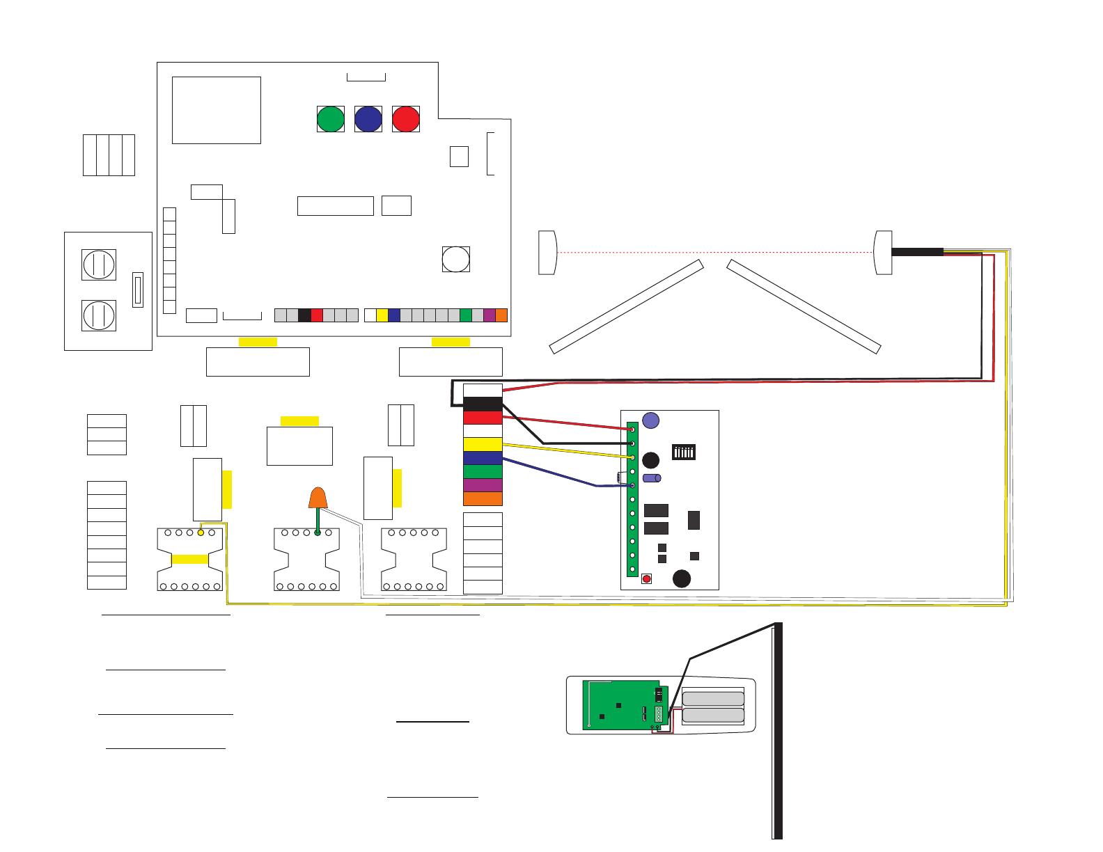
Photobeam Connection:
Disconnected the jumpered connection of the GREEN wire from the Shadow Base
and the Safety Base from Pin 5 of the Shadow Base. Wire nut the WHITE wire of
the photobeam to the GREEN wire at the Safety Base. Connect the common wire
of the photobeam (YELLOW) to Pin 5 of the Shadow Base. Connect the RED wire
of the photobeam to Terminal #24+. Connect the BLACK wire of the photobeam to
Terminal #18 (see diagram below).
In this example, all accessories are wired as NORMALLY CLOSED on a BYAN SYSTEMS
3-base pre-wired backplate. Only one accessory can be connected through Terminals
#24+ and #18 on the pre-wired backplate. The second accessory will be connected to
Terminals #18 and #19. (Either accessory can be wired as Car Safe OR as People Safe.)
Sensing Edge Connection:
Connect the power from the RECEIVER of
the sensing edge by connecting the BLACK
wire to the second terminal on the receiver and
connecting the other end to Terminal #18 of
the pre-wired backplate. Next connect the
RED wire to the first terminal of the
receiver and connect the other end to Terminal
#19 of the pre-wired backplate. Connect the
common wire of the receiver (YELLOW) to the
thir terminal of the receiver, connecting the
other end to Terminal #21 of the pre-wired
backplate. Lastly, connect the Normally Closed
wire (BLUE) to the fifth terminal of the receiver
to Terminal #20 (People Safe) on the pre-wired
backplate (see diagram to the left).
Safety1 Safety2
Configuration
ON
Safety1 Type
Safety2 Type
Low Power
Frequency
F
Prog/Test1 Prog/Test2
Transmitter Solutions
iGAZERE Transmitter
Transmitter Solutions
iGAZEREKIT-UL Receiver
ON
12 3 4 5 6
Test Polarity
Buzzer OFF
Frequency
Out1 10K
Out2 10K
Make sure your DIP Swtiches are set
correctly. On your RECEIVER, set all
6 switches to the OFF position. On the
TRANSMITTER also set all 6 switches
to the OFF position. (These are the
way they come directly from Transmitter
Solutions for this model.)

