Smoke Hollow 7000CGS Owner's manual
- Category
- Barbecues & grills
- Type
- Owner's manual

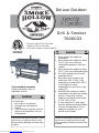
Grill & Smoker
7000CGS
Tools needed for assembly:
Phillips screwdriver, Pliers or
Adjustable Wrench
If you smell gas:
1. Shut off gas to the appliance.
2. Extinguish any open appliance.
3. Open lid.
4. If odor continues, keep away from the
appliance and immediately call your
fire department.
Failure to follow these instructions could
result in fire or explosion which could
cause property damage, personal injury
or death.
DANGER
1. Never operate this appliance
unattended.
2. Never operate this appliance within
10 ft (3.0 m) of any structure,
combustible material or other gas
cylinder.
3. Never operate this appliance within
25 ft (7.5 m) of any flammable liquid.
4. Do not fill cooking vessel beyond
maximum fill-line.
5. Never allow oil or grease to get
hotter than 400F or 200C. If the
temperature exceeds 400F (200C)
or if oil begins to smoke,
immediately turn the burner or gas
supply OFF.
6. Heated liquids remain at scalding
temperatures long after the cooking
process. Never touch cooking
appliance until liquids have cooled
to 115F (45C) or less.
7. If a fire should occur, keep away
from the appliance and immediately
call your fire department. Do not
attempt to extinguish an oil or
grease fire with water.
Failure to follow these instructions could
result in fire or explosion which could
cause property damage, personal injury
or death.
DANGER
Conforms to ANSI STD Z21.58a-2008
Certified to CSA STD 1.6a-2008
OUTDOOR COOKING GAS APPLIANCES
Deluxe Outdoor
Downloaded from www.Manualslib.com manuals search engine

2
For Outdoor Use Only
(outside of any type of enclosure)
WARNING
If you smell gas –
● Turn off the gas supply to the
appliance
● Extinguish any and all open flames
● Open the Lid of the Grill
● If the odor remains, stay away from
the grill and notify your gas supplier
and/or the Fire Department.
WARNING
● Do not use or store gasoline,
kerosene, alcohol, or other
flammable liquids or vapors in the
vicinity of this appliance or any
other appliance.
● Any LP Gas Cylinder NOT
connected for use with the
appliance, shall not be stored in the
same vicinity of this or any other
appliance.
A LP Propane Gas Cylinder is
needed for operating the gas side of
this grill.
The LP Gas Cylinder is NOT
included.
This gas grill is only intended for
Domestic use, not to be used for any
commercial purpose.
WARNING
● Never use the gas or charcoal grill
for INDOOR cooking or heating
● Never use the grill on or in a boat or
recreational vehicle
The combustion fumes from either
the gas or charcoal grill are toxic and
can cause severe illness and possibly
death.
DANGER
The combustion of Propane gas can
yield the formation of chemical
compounds known in the state of
California,U.S.A., to cause birth
defects,cancer,and other serious
health matters.
WARNING
Read this installation manual before
assembling or servicing this appliance.
Failure to follow these instructions may
result in an faulty installation, which
could cause damage to property,
WARNING
Save these instructions after reading
them in case you need to refer to them
in the future.
IMPORTANT
Downloaded from www.Manualslib.com manuals search engine

3
Read all safeguards and assembly
instructions before assembling and
operating your grill/smoker.
Before assembling your new grill/smoker,
unpack all the parts from the box.
Carefully remove all packing material and
lay out all the parts for easy access and
identification. Do not discard the carton or
packaging until your smoker is fully
assembled and operating to your
satisfaction.
In order to properly assemble your
smoker, you will only need two tools:
● Phillips head screwdriver
● Pliers or adjustable wrench
(tools not included)
The grill/smoker is heavy and must be
moved around during assembly and
before use. Be sure to have a friend
help.
Outdoor Leisure Products, Inc.
5400 Doniphan Drive
Neosho, MO 64850
Toll Free: 866-475-5180
Website: www.olp-inc.com
8:30am to 4:30pm, Central Time
Monday through Friday
Downloaded from www.Manualslib.com manuals search engine

4
SAFETY WARNINGS
1. The installation of this grill must conform to local codes, or in the absence of local codes, with either
the National Fuel Gas Code, ANSI Z223.1 / NFPA 54, Natural Gas and Propane Installation Code, CSA
B149.1, or Propane Storage and Handling Code, B 149.2, or The Standard for recreational Vehicles,
ANSI 119.2 / NFPA, and CSA Z240 RV Series, Recreational Vehicle Code, as Acceptable.
2. The Gas Grill side of the 47180T is for use with LP (Propane) Gas ONLY! LP Gas Cylinder is NOT
included with the Grill.
3. Never use lighter fluid, gasoline, kerosene, or alcohol for lighting the gas grill.
4. The LP Gas supply Cylinder used must be constructed and marked in accordance with
the Specifications of the U.S. Department of Transportation (D.O.T.) or The Standard for
Cylinders, Spheres and Tubes for Transportation of Dangerous Goods; and
Commission, CAN/CSA-B339, as applicable. It MUST be provided with a Listed Overfilling
Device. Only use 20 pound cylinders that have a type 1 cylinder connection device compatible with the
Connection for Outdoor Cooking Appliances.
5. The LP gas cylinder must be arranged for vapor withdrawal, purging and have an overfilling
prevention device.
6. LP Gas Cylinders must be stored outdoors, out of the reach of children, and must not be
stored in a building, garage or any other enclosed area.
7. The Pressure regulator and Hose Assembly supplied with the Grill, must be
used. Any replacement regulator and hose assemblies must be those specified by the
outdoor cooking gas appliance manufacturer.
8. The LP Gas Cylinder must include a collar to protect the cylinder valve.
9. Do not store a spare LP Gas Cylinder under or near this grill.
10. Never fill the LP Gas Cylinder beyond 80% full. For vapor withdrawal /purging, The cylinder should be
in the upright position.
11. This outdoor cooking gas appliance must only be used outdoors, and must not be
used in a building, garage or any enclosed area
12. The following distances for proper clearance must be maintained :
● Minimum distance from back and sides of the outdoor cooking gas appliance
● to walls is 36" ( 1 meter )
● Do not use under any overhead combustible constructions
● For outdoor use only
● Remove LP Gas Cylinder from grill if storing grill indoors
13. This outdoor cooking gas appliance is not intended to be installed in or on boats
14. Inspect the Gas Hose before each use. If the Hose has any leak, cut or wear,
it must be replaced BEFORE using the grill
15. Do not try to move the grill while either gas, charcoal or smoker firebox is lit.
16. Wait one hour minimum before touching any metal parts, until they are cool.
17. NEVER leave the grill unattended when in use.
18. Keep children and pets away from the grill when in use.
IF THESE INSTRUCTIONS ARE NOT FOLLOWED EXACTLY, A FIRE CAUSING
DEATH OR SERIOUS INJURIES MAY OCCUR!
Downloaded from www.Manualslib.com manuals search engine

5
READ ALL SAFEGUARDS AND INSTRUCTIONS THOROUGHLY!
YOUR SAFETY IS VERY IMPORTANT – FAILURE TO FOLLOW PROPER PROCEDURES AND
SAFEGUARDS MAY RESULT IN PROPERTY DAMAGE, PERSONAL INJURY OR DEATH.
DANGER DANGER
● The GRILL is for outdoor use only!
● Do NOT use this grill for other than its intended
purpose.
● Do not leave grill unattended when in use.
● Do not use gasoline, kerosene or alcohol for
lighting charcoal, use of any of these or similar
products may cause an explosion possibly leading
to severe bodily harm.
● Never operate this grill under any overhead roof
covering, awning or overhang. Never use inside
an enclosed area such as screen patios, garages,
buildings or tents.
● Keep the area clear of all flammable liquids,
combustible material including but not limited to
wood, dry plants including grass, brush, paper,
and canvas.
● Grill is HOT while in use and after use – Avoid
touching hot surfaces. Always wear protective
gloves or mitts when operating the smoker.
● Keep children and pets away from the grill at all
times.
● Do not allow anyone to conduct activities around
the grill during or following its use until the unit
has cooled. The grill is hot during operation and
remains hot for a period of time following its use.
● Always wear shoes and protective clothing during
operation of this smoker.
● Never use glassware, plastic, or ceramic
cookware in this grill.
● The firebox lid will be extremely hot.
● When grilling, grease from meat may drip into the
charcoal and cause a grease fire. If this should
happen, close the lid and dampers to suffocate
the flame.
● Do not use water to extinguish grease fires.
● Do not move the unit while it is being used.
● Do not use in windy conditions.
● Use caution when opening the lid, as hot stream
or a flame flare-up could cause burns.
● Before each use, make sure the unit is in good
working condition.
● Use caution after the fire has been extinguished,
the surface will remain hot for some time.
● Be sure all charcoals are cold before emptying, if
necessary pour water on coals before moving
grill.
● Store the grill out of reach of children and in a dry
location when not in use.
● Check grease and or ash level in ash pan often
and empty. Use extreme caution as the smoker,
and metal ash pan will be hot.
● When opening the lids, keep hands, face and
body a safe distance from hot steam and flame
flare-ups.
● Do not allow charcoal and or wood to rest on the
walls of the firebox and cooking chamber. Doing
so will greatly reduce the life of the metal and
finish of you smoker.
● Close lids and all dampers to suffocate flame.
● Never leave coals and ashes in grill unattended.
Before grill can be left unattended, remaining
coals and ashes must be removed from smoker.
● Use caution when lifting or moving smoker to
prevent strains and back injuries.
● Properly dispose of all packaging material.
USE CAUTION AND COMMON SENSE WHEN OPERATING YOUR SMOKER. READ ALL INSTRUCTIONS,
WARNINGS AND SAFEGUARDS PRIOR TO ASSEMBLING AND OPERATING YOUR SMOKER.
SAVE THESE INSTRUCTIONS
Downloaded from www.Manualslib.com manuals search engine

6
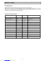
7000CGS Parts List
Note: For assistance, including missing or damaged parts, call toll free - 866-475-5180
from 8:30 am - 4:30 pm Central Time, Monday - Friday
Hardware Pack
Item Number Quantity Description
1 76 M6 x 15 Combo Truss Head Bolts, Black Nickel Plated
2 24 M6 x 8 Combo Truss Head Bolts, Black Nickel Plated
3 4 M6 x 25 Combo Truss Head Bolts, Black Nickel Plated
4 2 ST4.2 x 10 Screws. Black Nickel Plated
5 14 M6 KEPS Nuts, Black Nickel Coated
6 2 Hinge Pins, Black Nickel Coated
7 2
"R" Clips, Black Nickel Coated
8 1 M6 Metal Lock Nut, Black Nickel Plated
Downloaded from www.Manualslib.com manuals search engine

7
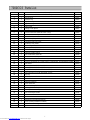
7000CGS Parts List
Item NO. Quantity Description Part NO.
1 1 Gas and Charcoal Cabinet and Lid Assembly TR001
2 1 Left Front Leg TR002
3 1 Left Rear Leg TR003
4 1 Right Front Leg TR004
5 1 Right Rear Leg TR005
6 1 Bottom Shelf TR006
7 4 Locking Caster Wheel TR007
8 12 Handle Stand-off TR008
9 2 Gas and Charcoal Lid Handle Tube (Long) TR009
10 1 Smoke Stack Assembly TR010
11 1 Grease Pan Connector TR011
12 1 Left Side, Drip Tray Guide TR012
13 1 Right Side, Drip Tray Guide TR013
14 1 Center Drip Tray Guide TR014
15 1 Firebox Support Brace TR015
16 1 Firebox Door Handle TR016
17 4 Handle Tube for Firebox, Sear Burner, and Drip Trays TR017
18 1 Firebox Assembly and lid TR018
19 1 Charcoal Basket Lift Handle TR019
20 1 Charcoal Basket Lift System TR020
21 1 Sear Burner Housing and Lid Assembly TR021
22 1 Gas Hose, Regulator,(4) Control Valves, Control Knobs, and Manifold Assembly TR022
23 1 Sear Burner TR023
24 1 Retaining Bracket for LP Gas Cylinder TR024
25 1 Retaining Wire for LP Gas Cylinder TR025
26 2 Long Fence Rail ( for Front and Back of Grill) TR026
27 2 Short Fence Rail ( for both Side Ends of Grill) TR027
28 2 Drip Tray TR028
29 1 Match Holder and Chain TR029
30 1 Charcoal Basket TR030
31 1 Firebox Wood Rack TR031
32 3 Burner Heat Tent TR032
33 1 Firebox Cooking Grid TR033
34 5 Cooking Grid - for Gas / Charcoal /Sear Burner TR034
35 2 Warming Rack Assembly TR035
36 1 Charcoal Damper Handle TR036
37 4 Burner Control Knob TR037
38 1 Hardware Pack TR038
39 1 Installation and Instruction Manual TR039
40 3 Burner, (factory installed in Cabinet) TR040
41 2 Heat Indicator with wing nut TR041
42 1 Igniter TR042
Downloaded from www.Manualslib.com manuals search engine

8
Assembly
Note: Carefully cut the straps holding the carton together. Cut the carton sleeve so that it can
lay flat on the ground to provide a clean surface for assembling your Grill. Remove the packing
materials and all the parts from inside the Cabinet. After unpacking all the parts, check to make
sure you HAVE all the parts. If anything is damaged or missing, contact our toll free number:
866-475-5180. Discard all packing material in a safe and recyclable manner. Save this
Assembly Manual for future reference.
Tools Required: Phillips Head Screwdriver, Adjustable Wrench or Pliers
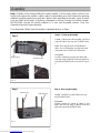
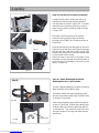
Step 1: Front Leg Assembly
Locate: Cabinet and Lid Assembly, Left Front
Leg and Right Front Leg and (7) M6x15 bolts.
Note: Each leg will have an identification
label. Do not fully tighten any leg bolts until
instructed to do so later in the assembly.
Procedure:
Position cabinet on its back and attach left
front leg using (3) M6x15 bolts and right front
leg using (4) M6x15 bolts as shown in Figure
1.
Step 1
Step 2 Step 2: Rear Leg Assembly
Locate: Left Rear Leg and Right Rear Leg
and (6) M6x15 bolts.
Procedure:
Position cabinet as shown in Figure 2 and
attach left rear leg using (2) M6x15 bolts and
right rear leg using (4) M6x15 bolts.
Right Front Leg
Left Front Leg
Fig. 2
Fig. 1
Right Rear Leg
Left Rear Leg
Downloaded from www.Manualslib.com manuals search engine

9
Assembly
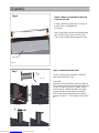
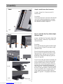
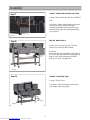
Step 3: Bottom Shelf Assembly
Locate: Bottom Shelf and (8) M6x15 bolts.
Procedure:
Attach bottom shelf as shown in Figure 3.
Note: The end of the Bottom Shelf with the
reinforcement plates must be positioned at
the left end of the grill as shown in figure 3.
FULLY TIGHTEN ALL BOLTS USED IN
STEPS 1, 2 AND 3.
Step 3
Step 4 Step 4: Caster Wheel Assembly
Locate: 4 Caster Wheels
Procedure:
Insert the threaded end of the caster wheel
into the bottom of each leg as shown in Figure
4 and fully tighten with the wrench provided in
the hardware pack.
Fig. 3
Bottom Shelf
Fig.4
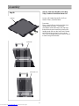
Step 5: Check your Progress
Stand the grill up onto its caster wheels and it
should look like the image in Figure 5.
Step 5
Fig. 5
Reinforcing Plate
Downloaded from www.Manualslib.com manuals search engine

10
Assembly
Step 6
Step 6: Attach Long Handles to Gas and
Charcoal Grill Lids
Locate: (4) Handle Stand-offs, (2) Long Lid
Handle Tubes, (8) M6x8 bolts.
Procedure:
Open the grill lids and place the handle stand-
offs over the holes in each end of the lids.
Then insert an M6x8 bolt through each hole.
Grill Lid
Fig. 6
Step 7: Attach the Smoke Stack
Locate: Smoke Stack Assembly, (4) M6x15
bolts and (4) M6 KEPS nuts.
Procedure:
Remove smoke stack lid as shown in Figure 7A.
Then insert smoke stack through grill lid from the
inside as shown in Figure 7B. Attach smoke
stack to the lid. M6x15 bolts will be inserted
through the lid from the outside and the M6
KEPS nuts will be positioned on the inside as
shown in Figure 7C. Then replace smoke stack
lid.
Step 7
Fig. 7A
Fig. 7B Fig. 7C
Downloaded from www.Manualslib.com manuals search engine

11
Assembly
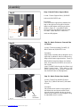
Step 8 Step 8: Install Grease Pan Connector
Locate: Grease Pan Connector and (2)
M6x15 bolts.
Procedure:
Place the grease pan connector inside the left
end of the cabinet just below the horizontal
slot and insert (2) M6x15 bolts from outside
the cabinet as shown in Figure 8.
Fig.8
Step 9
Fig. 9A Fig. 9B
Step 9: Install the Drip Tray Guides (Right,
Left and Center)
Locate: Left Side Drip Tray Guide, Right Side
Drip Tray Guide, Center Drip Tray Guide and
(10) M6x15 bolts.
Procedure:
Place right side drip tray guide inside the right
legs as shown in Figure 9A and attach using
(4) M6x15 bolts.
Place left side drip tray guide inside the left
legs as shown in Figure 9B and attach using
(4) M6x15 bolts. Be sure the LP gas line is
positioned outside the left drip tray guide as
shown in Figure 9B.
From in front of the grill, find the threaded hole
on the underside of the cabinet and partially
insert an M6x15 bolt as shown in Figure 9C.
Position the center drip tray guide so that the
keyhole fits over the partially installed bolt
(See Figure 9D). Then push the guide toward
the back of the grill cabinet so that the tab fits
over the threaded hole in the lower back side
of the cabinet and insert an M6x15 bolt as
shown in Figure 9E. Fully tighten both M6x15
bolts.
Fig.9C
Fig.9E
Fig.9D
Stop tab
Downloaded from www.Manualslib.com manuals search engine

12
Assembly
Step 10: Attach the Handles to the Drip
Trays, Firebox Lid and Sear Burner Lid
Locate: (8) Handle Stand-offs, (4) Short
Handle Tubes, (16) M6x8 bolts .
Procedure:
Place a stand-off onto each end of the short
handle tubes as shown. The handle
assemblies will be attached to the drip trays,
firebox lid and sear burner lid by placing the
handle stand-offs over the holes and inserting
an M6x8 bolt through each hole as shown.
This is the same procedure you used in Step 6
to attach the grill lid handles.
Step 10
Drip tray
Firebox lid
Sear burner lid
Downloaded from www.Manualslib.com manuals search engine

13
Assembly
Step: 11 Install Firebox Support Brace
Locate: Firebox Support Brace, (4) M6x15
bolts and (4) M6 KEPS nuts.
Procedure:
Place the firebox support brace between the
legs on the right end of the grill so that the
ledge is at the bottom and facing to right as
shown in Figure 11. Insert M6x15 bolts
through the legs and then through the brace
as shown. Attach M6 KEPS nuts on the
inside and fully tighten.
Step 12: Attach Firebox to Charcoal Side
of Cabinet
Locate: Firebox Assembly (Part #18), (6)
M6x15 bolts and (6) M6 KEPS nuts.
Procedure:
Align firebox assembly with rectangular hole in
right side of cabinet so that it is resting on the
ledge of the firebox support bracket. Insert (3)
M6x15 bolts through the firebox and cabinet
wall. Then attach an M6 KEPS nut to each of
the (3) bolts.
Insert (3) M6x15 bolts through the firebox and
firebox support brace. Then attach an M6
KEPS nut to each of the (3) bolts. Make sure
the (6) M6x15 bolts are fully tightened.
Step 11
Step 12
Fig. 11
Lock nut
Fig. 12
Fig. 13
Step 13: Attach Firebox Door Handle
Locate: Firebox Door Handle (Shown in
Figure 13), (1) M6x15 bolt and (1) M6 metal
lock nut.
Procedure:
Place firebox door handle on the outside of
the firebox door and insert an M6x15 bolt
through the door handle and door as shown.
Attach an M6 metal lock nut and tighten using
an adjustable wrench or pliers.
Ledge
Firebox
door handle
Downloaded from www.Manualslib.com manuals search engine

14
Assembly
Step 14: Installing the Charcoal Basket
Lifting System
Locate: Charcoal Basket Lift Handle, Charcoal
Basket Lifting System, (4) M6x15 bolts, (2)
Hinge Pins and (2) “R” Clips
Procedure:
Slide the charcoal basket lift handle through the
adjusting slot and through the hole of the inside
plate as shown in Figure 14A. Align the hole in
the end of the lift handle with the holes in the “U”
shaped bracket located at the back of the
cabinet. Join the lift handle and the “U” shaped
bracket by inserting a hinge pin as shown in
Figure 14B. Then insert an “R” clip though
the hole in the hinge pin.
Place the charcoal basket lifting system into the
cabinet and attach it to the back wall by inserting
(4) M6x15 bolts through the back side of the
cabinet wall as shown in Figure 14C.
Attach the charcoal basket lift handle to the
charcoal basket lifting system by inserting a
hinge pin through the “U” shaped lifting arm and
the hole in the center of the lifting handle as
shown in Figure 14D. Then insert an “R” clip
through the hole in the hinge pin.
You should now be able to adjust the charcoal
basket lifting system to your desired height by
moving the lifting handle to the left and raising or
lowering it.
Step 14
Fig.14 B
Hole
Fig.14A
Inside Cabinet
Fig.14C
Fig.14D
Downloaded from www.Manualslib.com manuals search engine

15
Assembly
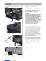
Step 15: Sear Burner Assembly
Locate: Sear Burner Housing and Lid (Part
21), Sear Burner, Sear Burner Control Knob,
(5) M6x15 bolts and (2) M4x10 bolts.
Procedure:
Attach the sear burner housing to the left end
of the grill cabinet with (5) M6x15 bolts (See
Figure 15A). Insert (1) M6x15 bolt through the
hole in the grill cabinet and into the sear
burner housing as shown in Figure 15B. Then
insert (2) M6x15 bolts through the sear burner
housing and into the grill cabinet. The last (2)
M6x15 bolts are inserted through the
underside of the sear burner housing and
through the leg into the grill cabinet.
The next step is to attach the sear burner
valve to the sear burner housing. Remove the
(2) M4x8 screws from the sear burner valve
as shown in Figure 15C. Then position the
valve in place between the front panel of the
sear burner housing and the inner wall as
shown in Figure 15D. Align the threaded
holes in the valve with the holes in the sear
burner housing and attach using the (2) M4x8
bolts that were removed earlier.
Place the sear burner control knob over the
valve stem, making sure to align flat portion of
both components, and push the control knob
over the stem until it is firmly seated. See
Figure 15E. Use this same procedure to
install the (3) gas control knobs on the gas
grill control panel.
(Sear Burner Assembly continued on next
page)
Step 15
Fig. 15A
Fig. 15C
Fig. 15D
Fig. 15E
Fig. 15B
Downloaded from www.Manualslib.com manuals search engine

16
Assembly
(Step 15: Sear Burner Assembly Continued)
Locate the sear burner, tilt the sear burner up
and slide the tube through the inner wall and
onto the valve as shown in Figure 15F. From the
underside of the sear burner housing, check to
make sure the valve is inside the tube as shown
in Figure 15G.
Now attach the Sear Burner to the bracket
located on the back wall of the Sear Burner
Housing using (2) M4.2 x10 Screws as shown in
Figure 15H.
Remove the large nut from the igniter as shown in
Figure 15I, push the other end of the wire through
the hole into the underside of the housing. And
slide the wire through the nut and through the hole
on the outside of the housing.
Attach the wire to the stem of the igniter. Push
the igniter and wire through the hole and attach it
to the housing by screwing the nut back onto the
igniter. Figure 15J.
Step 16: Attach Retaining Bracket and
Retaining Wire for LP Gas Cylinder
Locate: Retaining Bracket (Part # 24), Retaining
Wire (Part #25) and (2) M6x15 bolts.
Procedure: Attach the retaining bracket to the
left end of the bottom shelf using (2) M6x15 bolts
as shown in Figure 16A.
Attach retaining wire to legs at left end of grill as
shown in Figure 16B. Position the retaining wire
inside the legs and under the grill body with the
curved side up. Then insert the ends of the wire
through the holes in the legs and rotate the wire
toward you.
Step 16
Fig.16A
Fig.16B Retaining Wire
Fig. 15 F Fig. 15 G
Fig. 15 H Fig. 15 I
Fig. 15 J
Downloaded from www.Manualslib.com manuals search engine

17
Assembly
Step 17: Attach Match Holder and Chain
Locate: Match Holder & Chain and (1) M6x15
bolt.
Procedure: Attach match holder and chain to
the top rear hole in the left rear leg by
inserting an M6x15 bolt through the loop at
the end of the chain and securely tightening.
See Figure 17.
Step 18 Step 18: Attach Fence
Locate: (2) Long Fence Pieces, (2) Short
Fence Pieces and (16) M6x15 bolts.
Procedure:
Attach the four pieces by aligning the holes at
the end of each piece with the corresponding
holes in each leg and inserting (2) M6x15
bolts at each end. See figure 18.
Step 19: Install Drip Trays
Locate: (2) Drip Trays
Procedure: Slide the drip trays under each
grill using the drip tray guides.
Fig.17
Step 17
Step 19
Fig.19
Fig.18
Drip Trays
Downloaded from www.Manualslib.com manuals search engine

18
Assembly
Step 20: Attach Charcoal Damper Handle
Locate: Charcoal Damper Handle
Procedure:
Screw the handle into the hole located above
the vertical slots on the charcoal side of the
grill. The handle should slide back and forth
to open and close the damper.
Step 20
Step 21: Install Warming Rack
Locate: (2) Warming Rack and (4) M6x25
bolts
Procedure: To attach the warming rack, insert
(1) of the M6x25 bolts through the lid from the
outside as shown in Figure 21A and position
the warming rack so that the bolt is going
through the wire loop as shown in Figure 21B.
Then align the wire loop on the opposite end
of the warming rack with the opposite lid hole
and insert the other M6x25 bolt.
Insert the wire legs into the holes on the sides
of the cabinet as shown in Figure 21C.
Step 21 Fig. 21A
Fig. 21B Fig. 21C
Downloaded from www.Manualslib.com manuals search engine

19
Assembly
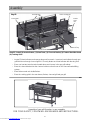
Step 22: Install (2) Heat Indicators, (3) Heat Tents, (1) Charcoal Basket, (1) Firebox Wood Rack and
(6) Cooking Grids.
· Locate (2) Heat Indicators and remove wing nuts from each. Insert one heat indicator through gas
grill lid and one through charcoal grill lid. Securely fasten each heat indicator with the wing nuts.
· Place one heat tent onto the tabs located above each burner in the gas grill cabinet.
· Place the charcoal basket into the charcoal cabinet so that it rests on the charcoal basket lifting
system.
· Place firebox wood rack inside firebox.
· Place the cooking grids in the sear burner, firebox, charcoal grill and gas grill.
Assembly of your grill & smoker is now complete.
FOR YOUR SAFETY, FOLLOW ALL SAFEGUARDS AND INSTRUCTIONS.
Step 22
Cooking grids
Burner Heat Tents
Firebox Cooking grid
Firebox
wood
rack
Charcoal Tray
Heat Indicators
Downloaded from www.Manualslib.com manuals search engine

20
● The LP Gas Cylinder must be a 20 pound cylinder and have a Type 1 Cylinder Valve Outlet
Connector
● Handle the Cylinder with care - do not drop it
● When you are not using the grill, the LP Gas Cylinder should be
disconnected
● Connect the regulator and hand tighten firmly
● Do a leak test each time you connect a LP Gas Cylinder and before
lighting the grill
● Never use a match or lit flame to test for leaks
● To test, prepare a weak solution of detergent and water. Spray or
swab the
● solution onto the connection of the regulator to the LP Gas Cylinder valve, and
● on all the joints in the hose connections up to the burner valves (which MUST be
● closed in the "OFF" position). Open the LP Gas Cylinder valve, and watch for any
● bubbles to appear at all the connection points. No bubbles indicate - All Clear!
● If there are any bubbles, there is a leak which must be fixed.
● Never obstruct the flow of combustion and ventilation air.
Connecting the LP gas cylinder to the grill
Lighting the grill
● Always open the Lid before lighting the grill.
● All burner knobs should be in the "OFF" position.
● Open the LP Gas Cylinder valve.
● Note: EACH of the 3 main burners on your grill has its own automatic igniter.
● Push the knob in fully, and slowly turn it counter-clockwise (to the left) to the "HIGH" position.
You will hear a loud "Click" as the igniter sparks and lights the burner
● You can then adjust the knob to your desired setting.
● If the burner did not light, turn the knob back to the “OFF” position, wait 5 minutes for any gas
to clear away, and then repeat the lighting procedure.
● For Sear Burner, turn the knob counter-clockwise (to the left) and then PUSH the Black
Igniter Button several times to light the burner. If the burner does not light ,then turn the knob
to the “OFF” position, wait 5 minutes and then try again.
● After using the grill, - turn all burner knobs to the "HIGH" position and then push fully in and
turn to the "OFF" position.
● At once turn the valve on the LP Gas Cylinder OFF.
● IF the auto-igniter does NOT light the burner, you can light
it
● with a match or a piece of burning paper - hold the match
or paper with the Match Holder ( attached at the side of the
grill) , put it through the openings in the Cooking Grid and
next to the Flame Tent covering the burner. Then follow the
lighting procedure above.
● Observe the proper burner flame - it should be a blue/yellow color about 1/2” long.
Sear Burner Operation
● ALWAYS be sure to OPEN the Lid before lighting the Sear Burner
● Preheat the Burner for 5 minutes
● Sear one side of the food, turn the food over and sear the other side. Then continue cooking
each side of the food on the standard burners until done to your satisfaction
● When finished, leave the Sear Burner on for a few minutes to burn off grease or food residue
OPERATING INSTRUCTIONS
"click”
OFF
OFF
YELLOW
BLUE
Burner
Good Flame Bad Flame
Downloaded from www.Manualslib.com manuals search engine
Page is loading ...
Page is loading ...
Page is loading ...
Page is loading ...
Page is loading ...
Page is loading ...
Page is loading ...
Page is loading ...
-
 1
1
-
 2
2
-
 3
3
-
 4
4
-
 5
5
-
 6
6
-
 7
7
-
 8
8
-
 9
9
-
 10
10
-
 11
11
-
 12
12
-
 13
13
-
 14
14
-
 15
15
-
 16
16
-
 17
17
-
 18
18
-
 19
19
-
 20
20
-
 21
21
-
 22
22
-
 23
23
-
 24
24
-
 25
25
-
 26
26
-
 27
27
-
 28
28


Smoke Hollow 7000CGS Owner's manual
- Category
- Barbecues & grills
- Type
- Owner's manual
Ask a question and I''ll find the answer in the document
Finding information in a document is now easier with AI