Texas Instruments bq500414Q bqTESLA Wireless Power TX EVM (Rev. A) User guide
- Type
- User guide

User's Guide
SLVUA40A–March 2014–Revised January 2015
bq500414Q bqTESLA Wireless Power TX EVM
The bqTESLA™ wireless power transmitter evaluation module from Texas Instruments is a high-
performance, easy-to-use development module for the design of wireless power solutions. The
bq500414Q EVM evaluation module (EVM) provides all the basic functions of a Qi-compliant three coil, A6
type, wireless charger pad. The EVM is intended to be used with the bq51013BEVM-764 or any other Qi-
compliant receiver. Both the WPC 1.0 and WPC 1.1 receivers are supported with this design. The
bq500414QEVM-629 is a 12-V input design
Contents
1 Applications................................................................................................................... 2
2 bq500414QEVM-629 Electrical Performance Specifications .......................................................... 2
3 Modifications.................................................................................................................. 2
4 Connector and Test Point Descriptions................................................................................... 3
4.1 Connector and Test Point Descriptions.......................................................................... 3
4.2 Test Point Descriptions ............................................................................................ 3
5 Schematic and Bill of Materials ............................................................................................ 6
6 Test Setup................................................................................................................... 12
6.1 Equipment.......................................................................................................... 12
6.2 Equipment Setup.................................................................................................. 13
7 bq500414QEVM-629 Assembly Drawings and Layout................................................................ 16
8 Reference ................................................................................................................... 22
List of Figures
1 bq500414QEVM-629 Schematic........................................................................................... 6
2 bq500414QEVM-629 Schematic........................................................................................... 7
3 bq500414QEVM-629 Schematic .......................................................................................... 8
4 Equipment Setup........................................................................................................... 13
5 Efficiency versus Power, bq500414QEVM-629 Transmitter and HPA764 Receiver .............................. 14
6 Assembly Top............................................................................................................... 16
7 Top Overlay................................................................................................................. 17
8 Top Solder................................................................................................................... 18
9 Top Layer.................................................................................................................... 19
10 Inner Layer 1................................................................................................................ 20
11 Inner Layer 2................................................................................................................ 21
12 Bottom Layer................................................................................................................ 22
List of Tables
1 bq500414QEVM-629 Electrical Performance Specifications .......................................................... 2
2 Bill of Materials .............................................................................................................. 9
bqTESLA is a trademark of Texas Instruments.
Avid is a registered trademark of Avid Technology, Inc..
1
SLVUA40A–March 2014–Revised January 2015 bq500414Q bqTESLA Wireless Power TX EVM
Submit Documentation Feedback
Copyright © 2014–2015, Texas Instruments Incorporated

Applications
www.ti.com
1 Applications
The bq500414QEVM-629 evaluation module demonstrates the transmitter portion of the bqTESLA™
wireless power system. This transmitter EVM is a complete transmitter-side solution that powers a
bqTESLA™ receiver. The EVM requires only input power for operation, 12 Vdc at 1 A. All transmitter-side
electronics and transmitter coils are on a single 4-layer printed-circuit board (PCB). The open design
allows easy access to key points of the electrical schematic.
This EVM has the following features:
• WPC A6-Type transmitter coil, 70 mm × 20 mm free positioning area
• Designed for 12-Vdc systems
• Optional input power SEPIC converter to produce 12 Vdc from 6 V to 16 V
• Fully WPC 1.1 Foreign Object Detection (FOD) and WPC 1.0 Parasitic Metal Object Detection (PMOD)
• Reduced parts count from the legacy bq500410A design
• LED indicates power transfer or power fault state
2 bq500414QEVM-629 Electrical Performance Specifications
Table 1 provides a summary of the EVM performance specifications. All specifications are given for an
ambient temperature of 25°C.
Table 1. bq500414QEVM-629 Electrical Performance Specifications
Parameter Notes and Conditions Min Typ Max Unit
Input Characteristics
V
IN
Input voltage bq500414Q 6 12 16 V
I
IN
Input current V
IN
= 12 V, RX I
OUT
= 1 A at 5 V 570 mA
Input no-load current V
IN
= 12 V, I
OUT
= 0 A 72 mA
Input stand-by current V
IN
= 12 V 18.75 mA
Output Characteristics – Receiver bq51013BEVM-764
V
OUT
Output voltage V
IN
= Nom, I
OUT
= Nom 4.5 5 5.1 V
Output ripple V
IN
= Nom, I
OUT
= Max 200 mV
PP
I
OUT
V
IN
= Min to Max V
IN
= Min to Max 0 1 A
Output overcurrent V
IN
= Nom 1.1 A
Systems Characteristics
F
S
Switching frequency Switching frequency varies with load 120 205 kHz
ηpk Peak efficiency V
IN
= 12 V, P Out RX = 2.5 W 75%
η Full-load efficiency V
IN
= Nom, I
OUT
= Max 73.6%
3 Modifications
See the data sheet (SLUSBE4) when changing components.
Use LED mode – resistor R23 to change the behavior of the status LED, D2, D8 and D9. The standard
value is 42.2 kΩ for control option 1, see the datasheet for additional settings.
FOD threshold setting can be changed using R3. If R3 is removed then FOD function is disabled.
PMOD threshold setting can be changed using R22. If R22 is removed then PMOD function is disabled.
FOD_CAL can be used to change the slope of the FOD LOSS curve for better FOD performance, R52.
Addition of EMI Filter Shield, PWR633 to reduce emissions, see section 6.2.2.6
2
bq500414Q bqTESLA Wireless Power TX EVM SLVUA40A–March 2014–Revised January 2015
Submit Documentation Feedback
Copyright © 2014–2015, Texas Instruments Incorporated

www.ti.com
Connector and Test Point Descriptions
4 Connector and Test Point Descriptions
This section contains descriptions for the connectors and the test points.
4.1 Connector and Test Point Descriptions
The connection points are described in Section 4.1.1 through Section 4.1.3.
4.1.1 J1 – (Pin 1)V
IN,
(Pin 2) GND
Pin 1 - Input power 12 Vdc ±500 mV,
Pin 2 - Return for 12Vdc Input (Ground)
4.1.2 J2 – PMBus
Pin 6 - AGND
Pin 9 - PM_CLK
Pin 10 - PM_DATA
4.1.3 J3 –JTAG
Factory use only.
4.1.4 Control Headers
4.1.4.1 JP1 PMOD and FOD Enable / Disable
Shorting Jumper installed = Enable, removed = Disable
4.1.4.2 JP2 LED select bypass
Shorting Jumper installed = LED Bin 0
Default is not installed.
4.2 Test Point Descriptions
The test points are described in Section 4.2.1 through Section 4.2.15.
4.2.1 TP1 – Unused
Reserved – no connection.
4.2.2 TP2 – BUZ_DC
Output from IC to drive DC buzzer, signals start of power transfer.
4.2.3 TP3 – FOD
Select for FOD threshold
4.2.4 TP4 – COIL1.2
Output from bq500414Q, low enables coil 2 drive.
4.2.5 TP5 – PMOD
Select for PMOD threshold
3
SLVUA40A–March 2014–Revised January 2015 bq500414Q bqTESLA Wireless Power TX EVM
Submit Documentation Feedback
Copyright © 2014–2015, Texas Instruments Incorporated

Connector and Test Point Descriptions
www.ti.com
4.2.6 TP6 – Reserved
Reserved – no connection.
4.2.7 TP7 – Reserved
Reserved – no connection
4.2.8 TP8 – COIL1.3
Output from bq500414Q, low enables coil 3 drive.
4.2.9 TP9 – 12Vdc
System regulated 12V from VIN
4.2.10 TP10 - Reserved
Reserved – no connection
4.2.11 TP11 – Shield / No Shield
Input to configure bq500414Q to operate with EMI shield, PWR633. Low = no shield, high (3.3V) = shield
4.2.12 TP12 – 12Vdc Feedback
Feedback circuit for 12V regulator
4.2.13 TP13 – GND
Ground test point connection
4.2.14 TP14 – I_SENSE
Current as measured in the system 12V supply
4.2.15 TP15 – COMM-
Sample of coil voltage return for communications with RX
4.2.16 TP16 – COMM+
Sample of coil voltage for communications with RX
4.2.17 TP17 – Reserved
Reserved – no connection.
4.2.18 TP18 – DPWM-1A
PWM Output to half bridge drivers
4.2.19 TP19 – Reserved
Reserved – no connection.
4.2.20 TP20 – GND
Ground test point connection
4
bq500414Q bqTESLA Wireless Power TX EVM SLVUA40A–March 2014–Revised January 2015
Submit Documentation Feedback
Copyright © 2014–2015, Texas Instruments Incorporated

www.ti.com
Connector and Test Point Descriptions
4.2.21 TP21 – GND
Ground test point connection
4.2.22 TP22 – AGND
Analog ground test point connection
4.2.23 TP23 – COIL1.1
Output from bq500414Q, low enables coil 1 drive.
4.2.24 TP24 – AGND
Analog ground test point connection
4.2.25 TP25 – 3.3Vdc_EN
3.3Vdc enable signal to the regulator
4.2.26 TP26 – EN_PWR
Enable signal for the 12Vdc system regulator
4.2.27 TP27 – PWRGD
Power good signal from the 3.3Vdc regulator
4.2.28 TP28 – TANK3
Coil 3 Resonant Tank Drive Signal
4.2.29 TP29 – PHSE3
Coil 3 Drive signal
4.2.30 TP30 – GND
Ground test point connection
4.2.31 TP31 – PHSE1
Coil 1 Drive signal
4.2.32 TP32 – TANK2
Coil 2 Resonant Tank Drive Signal
4.2.33 TP33 – TANK1
Coil 1 Resonant Tank Drive Signal
4.2.34 TP34 – GND
Ground test point connection
4.2.35 TP35 – PHSE2
Coil 2 Drive signal
5
SLVUA40A–March 2014–Revised January 2015 bq500414Q bqTESLA Wireless Power TX EVM
Submit Documentation Feedback
Copyright © 2014–2015, Texas Instruments Incorporated

Vin = 6 to 16 VDC
VIN_FLTR
1µF
C2
1µF
C6
4.7µF
C10
4.7µF
C18
L2
GND
Vin
1
2
J1
Gnd
GND GND
GND
L1
4.70
R13
12VDC
B560C
D4
0.04
R64
TP20 TP21 TP22 TP24
22µF
C11
22µF
C37
10.0
R15
10.0
R18
AGNDGND
4.7µF
C34
1µF
C8 4.7µF
C35
GND
3V3_VCC
GND
1µF
C40
205k
R11
NoPop
R14
INA213-Q1
IN-
5
IN+
4
OUT
6
REF
1
GND
2
V+
3
U9
GND
BSZ0902NS
Q1
4.70
R29
3V3_VCC
0.01µF
C30
TPS40210DGQ
RC
1
SS
2
DIS/EN
3
COMP
4
FB
5
GND
6
ISNS
7
GDRV
8
BP
9
VDD
10
PWPD
11
U1
AGND
1µFC7
1.00k
R62
TP26
EN_PWR
AGND
100k
R51
270pF
C12
0.22µF
C13
1.00k
R26
270pF
C9
I_SENSE
GND
TP14
0.1µF
C57
GND GNDGND
GND
0.025
R30
TP9
GND
GND
2700pF
C17
AGND
49.9
R50
150pF
C36
TP12
5.10k
R12
49.9k
R6
3.09k
R24
GND
Net-Tie
12VDC
VIN_BRD
Schematic and Bill of Materials
www.ti.com
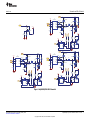
5 Schematic and Bill of Materials
This section includes the schematics and bill of materials for the EVM.
Figure 1 illustrates the schematic for this EVM.
Figure 1. bq500414QEVM-629 Schematic
6
bq500414Q bqTESLA Wireless Power TX EVM SLVUA40A–March 2014–Revised January 2015
Submit Documentation Feedback
Copyright © 2014–2015, Texas Instruments Incorporated

V_GATE
150k
R65
BC847CL
Q5
0.1µF
C66
249k
R7
GNDGND
NoPop
C21
0.068uF
C59
22µF
C58
DMG4800LSD
Q2A
10.0
R27
TPS28225-Q1
UGATE
1
BOOT
2
PWM
3
GND
4
LGATE
5
VDD
6
EN/PG
7
PHSE
8
U7
DPWM-1A
0.22uFC64
TP31
TP33
GND
COIL1.1 TANK1
NoPop
C23
0.068uF
C62
4700pF
C56
0.1µF
C65
0
R35
DMG4800LSD
Q2B
GND
GND GND
TP34
3V3_VCC
GND
COMM-
COMM+
TP15TP16
10.0
R61
200k
R28
BAT54SW
D5
3V3_VCC
23.2k
R63
0.1µFC55
33pF
C63
10.0
R2
COIL1.1
SN74LVC1G3157-Q1
B2
1
GND
2
B1
3
A
4
VCC
5
S
6
U4
TP23
10.0k
R66
AGND
5600pF
C14
0.068uF
C51
22µF
C50
V_GATE
Middle Coil
DMG4800LSD
Q3A
10.0R60
TPS28225-Q1
UGATE
1
BOOT
2
PWM
3
GND
4
LGATE
5
VDD
6
EN/PG
7
PHSE
8
U3
DPWM-1A
0.22uFC53
TP35
TP32
GND
COIL1.2 TANK2
5600pF
C15
0.068uF
C52
4700pF
C49
0.1µF
C54
0
R36
DMG4800LSD
Q3B
GND
GNDGND
TP30
3V3_VCC
GND
COMM+
COMM-
10.0
R34
200k
R19
BAT54SW
D6
3V3_VCC
23.2k
R21
0.1µFC32
33pF
C28
10.0
R16
COIL1.2
SN74LVC1G3157-Q1
B2
1
GND
2
B1
3
A
4
VCC
5
S
6
U5
TP4
10.0k
R20
AGND
NoPop
C24
0.068uF
C45
22µF
C44
V_GATE
DMG4800LSD
Q4A
10.0R59
TPS28225-Q1
UGATE
1
BOOT
2
PWM
3
GND
4
LGATE
5
VDD
6
EN/PG
7
PHSE
8
U2
DPWM-1A
0.22uF
C47
TP29
TP28
GND
COIL1.3 TANK3
NoPop
C27
0.068uF
C46
4700pF
C43
0.1µF
C48
0
R41
DMG4800LSD
Q4B
GND
GND GND
TP13
3V3_VCC
GND
COMM-
COMM+
10.0
R43
200k
R38
BAT54SW
D7
3V3_VCC
23.2k
R42
0.1µFC38
33pF
C33
10.0
R37
COIL1.3
SN74LVC1G3157-Q1
B2
1
GND
2
B1
3
A
4
VCC
5
S
6
U6
TP8
10.0k
R39
AGND
L4A
L4B
L4C
12VDC
VIN_BRD
V_GATE
VIN_BRD
VIN_BRD
www.ti.com
Schematic and Bill of Materials
Figure 2. bq500414QEVM-629 Schematic
7
SLVUA40A–March 2014–Revised January 2015 bq500414Q bqTESLA Wireless Power TX EVM
Submit Documentation Feedback
Copyright © 2014–2015, Texas Instruments Incorporated

3V3_VCC
10k
R67
FOR DEVELOPMENT ONLY
VIN_FLTRVIN_FLTR
0.1µFC61
3V3_VCC
330uH
L3
TPS54040-Q1
BOOT
1
VIN
2
EN
3
SS/TR
4
RT/CLK
5
PWRGD
6
VSENSE
7
COMP
8
GND
9
PH
10
PP
11
U8
0.1µF
C26
1.00
R47
348k
R48
TDO
JTAG
76.8k
R56
TP25
31.6k
R44
AGND
TDI
47µF
C29
2700pF
C42
/TRST
Remove Pin 6
TP27
NoPop
1
2
3
4
5
6
7
8
9
10
11
12
13
14
J3
4.7µF
C41
0.01µF
C60
22
R46
D10
MBR0530T1G
1
2
3
4
5
6
7
8
9
10
J2
10.0k
R54
226k
R49
887k
R55
AGND AGND AGNDAGND
AGND
10k
R68
1µF
C39
PMBus
4.7µFC54.7µFC19
10.0k
R25
PM_CLK
PM_DATA
AGND
1µFC1
1µFC3
1µF
C20
0.1µF
C22
AGNDAGND
VIN_FLTR12VDC 3V3_VCC
BQ500414Q
COIL_PEAK
1
T_SENSE
2
Unused
3
Unused
4
RESET
5
PMOD
6
LED_A
7
LED_B
8
LED_C
9
PMB_CLK
10
PMB_DATA
11
DPWM_A
12
FOD
13
Unused
14
COIL1.1
15
COIL1.2
16
COIL1.3
17
EN_PWR
18
RESERVED
19
RESERVED
20
EMI_SHIELD
21
FOD_CAL
22
BUZ_AC
23
BUZ_DC
24
COIL_SEL
25
RESERVED
26
RESERVED
27
RESERVED
28
RESERVED
29
RESERVED
30
RESERVED
31
GND
32
V33D
33
V33A
34
BPCAP
35
GND
36
COMM_A+
37
COMM_A-
38
COMM_B+
39
COMM_B-
40
RESERVED
41
I_SENSE
42
LOSS_THR
43
LED_MODE
44
V_SENSE
45
Unused
46
GND
47
ADCREF
48
EPAD
49
U10
/TRST
AGND
TDI
15.4k
R4
15.4k
R33
TDO
10.0k
R5
TP10
TP1 TP6
TP7
PM_DATA
PM_CLK
TP18
FOD
DPWM-1A
10.0
R8
I_SENSE
12
NTC
330pF
C4
TP3
PMOD
TP19
3V3_VCC
COIL1.1
TP5
COIL1.2
475R9
COIL1.3
475R32
AGND
3.57k
R17NoPop
R10
475R53
4700pF
C16
4700pF
C25
4700pF
C31
2.00k
R1
2.00k
R31
AGND
EN_PWR
TP17
TP2
1 2
BUZ
COMM+
10.0kR45
N/C
COMM-
BAT54SW
D3
10.0k
R57
AGNDAGND
COMM+
1 2
JP2
D2D8 D9
PMOD
133k
R22
AGND
STATUS
AGNDAGND AGND
1 2
JP1
42.2k
R23
FOD
56.2k
R3
AGND
FOD_CAL
0
R52
TCK
TCK
TMS
TMS
FOD_CAL
1.00k
R40
D1
D_LED_LTW-170TK
NoPop
R58
NoPop
R70
10.0k
R69
3V3_VCC
AGND
L5
L6
L7
AGND
TP11
EMI_SHIELD
EMI_SHIELD
3V3_VCC
AGND
AGND
Schematic and Bill of Materials
www.ti.com
Figure 3. bq500414QEVM-629 Schematic
Table 2 contains the BOM for this EVM.
8
bq500414Q bqTESLA Wireless Power TX EVM SLVUA40A–March 2014–Revised January 2015
Submit Documentation Feedback
Copyright © 2014–2015, Texas Instruments Incorporated

www.ti.com
Schematic and Bill of Materials
Table 2. Bill of Materials
(1)
Designator Quantity Value Description Package Reference PartNumber Manufacture
BUZ 1 Buzzer Piezoelectronic, 12 mm 12 mm PS1240P02CT3 TDK
C1, C3, C7, C20, C39, C40 6 1uF CAP, CERM, 1uF, 16V, +/-10%, X7R, 0603 0603 C1608X7R1C105K TDK
C2, C6 2 1uF CAP, CERM, 1uF, 50V, +/-10%, X7R, 1210 1210 GRM32RR71H105KA01L MuRata
C4 1 330pF CAP, CERM, 330pF, 50V, +/-5%, C0G/NP0, 0603 0603 C1608C0G1H331J TDK
C5, C19 2 4.7uF CAP, CERM, 4.7uF, 10V, +/-10%, X5R, 0603 0603 C0603C475K8PACTU Kemet
C8 1 1uF CAP, CERM, 1uF, 50V, +/-10%, X7R, 0805 0805 GRM21BR71H105KA12L MuRata
C9, C12 2 270pF CAP, CERM, 270pF, 50V, +/-5%, C0G/NP0, 0603 0603 C0603C271J5GACTU Kemet
C10, C18, C34, C35 4 4.7uF CAP, CERM, 4.7uF, 50V, +/-10%, X7R, 1210 1210 GRM32ER71H475KA88L MuRata
C11, C37 2 22uF CAP, CERM, 22uF, 16V, +/-20%, X7R, 1210 1210 C3225X7R1C226M TDK
C13 1 0.22uF CAP, CERM, 0.22uF, 16V, +/-10%, X7R, 0603 0603 C1608X7R1C224K TDK
C14, C15 2 5600pF CAP, CERM, 5600pF, 100V, +/-5%, C0G/NP0, 1206 1206 GRM3195C2A562JA01D MuRata
C16, C31, C43, C49, C56 5 4700pF CAP, CERM, 4700pF, 50V, +/-10%, X7R, 0603 0603 C0603X472K5RACTU Kemet
C17, C42 2 2700pF CAP, CERM, 2700pF, 50V, +/-5%, C0G/NP0, 0603 0603 C1608C0G1H272J TDK
C22, C32, C38, C48, C54, C55, 10 0.1uF CAP, CERM, 0.1uF, 50V, +/-10%, X7R, 0603 0603 GCM188R71H104KA57B MuRata
C57, C61, C65, C66
C26 1 0.1uF CAP, CERM, 0.1uF, 50V, +/-10%, X7R, 0603 0603 GRM188R71H104KA93D MuRata
C28, C33, C63 3 33pF CAP, CERM, 33pF, 50V, +/-5%, C0G/NP0, 0603 0603 GRM1885C1H330JA01D MuRata
C29 1 47uF CAP, CERM, 47uF, 25V, +/-20%, X5R, 1206 1206 C3216X5R1E476M160AC TDK
C30, C60 2 0.01uF CAP, CERM, 0.01uF, 50V, +/-10%, X7R, 0603 0603 GRM188R71H103KA01D MuRata
C36 1 150pF CAP, CERM, 150pF, 50V, +/-5%, C0G/NP0, 0603 0603 GRM1885C1H151JA01D MuRata
C41 1 4.7uF CAP, CERM, 4.7uF, 25V, +/-10%, X5R, 0805 0805 GRM21BR61E475KA12L MuRata
C44, C50, C58 3 22uF CAP, CERM, 22uF, 25V, +/-10%, X5R, 1210 1210 GRM32ER61E226KE15L MuRata
C45, C46, C51, C52, C59, C62 6 0.068uF Capacitor, Ceramic, 100V, C0G, 5% 1210 C3225C0G2A683J230AA TDK
C47, C53, C64 3 0.22uF Capacitor, Ceramic, 50V, X7R, 10% 603 C1608X7R1H224K080AB TDK
D1 1 LTW-170TK Diode. LED, 70 mW, 20mA 0805 LTW-170TK Lite-on
D2 1 RED Diode. LED, RED 0805 150080SS75000 Wurth
D3, D5, D6, D7 4 BAT54SW Diode, Dual Schottky, 200mA, 30V SOT323 BAT54SWT1G On Semi
D4 1 B560C Diode, 5A, 60V SMC B560C-13-F Diodes Inc.
D8 1 GREEN Diode. LED, GREEN 0805 150080VS75000 Wurth
D9 1 YELLOW Diode. LED, YELLOW 0805 150080YS75000 Wurth
D10 1 30V Diode, Schottky, 30V, 0.5A, SOD-123 SOD-123 MBR0530 On Semi
H52 1 Comb filter PCB 5.080" x3.050" x 0.031" 5.080"x3.050" x 0.031" PWR633 Any
J2 1 N2510-6002-RB Connector, Male Straight 2x5 pin, 100mil spacing, 4 Wall 0.338 x 0.788 inch N2510-6002RB 3M
L1 1 Inductor, SMT Dual Winding, CMC 0.492 x 0.492 inch 744284100 Wurth
L2 1 Inductor, SMT Dual Winding, SEPIC 0.492 x 0.492 inch 744871220 Wurth
L3 1 330uH Inductor, SMT 0.189 x 0.189 inch 744042331 Wurth
L4A, L4B, L4C 1 WPC A6 Coil Assembly, Triple coil 760308106 Wurth
L5, L6, L7 3 1000 ohm 0.2A Ferrite Bead, 1000 ohm @ 100MHz, SMD 0603 74279266 Wurth
Q1 1 BSZ0902NS MOSFET, NChan, 30V, 13A, 9.4 milliOhm QFN3.3x3.3 mm BSZ0902NS Infineon Technologies
Q2, Q3, Q4 3 DMG4800LSD MOSFET, DUAL NFET, 30V, SO8 DMG4800LSD-13 Diodes, Inc
(1)
Unless otherwise noted in the Alternate Part Number and/or Alternate Manufacturer columns, all parts may be substituted with equivalents.
9
SLVUA40A–March 2014–Revised January 2015 bq500414Q bqTESLA Wireless Power TX EVM
Submit Documentation Feedback
Copyright © 2014–2015, Texas Instruments Incorporated

Schematic and Bill of Materials
www.ti.com
Table 2. Bill of Materials
(1)
(continued)
Designator Quantity Value Description Package Reference PartNumber Manufacture
Q5 1 BC847CL TRANSISTOR, NPN, HIGH-PERFORMANCE, 500mA SOT-23 BC847CLT1G ON Semi
R2, R8, R15, R16, R18, R27, 12 10.0 RES, 10.0 ohm, 1%, 0.1W, 0603 0603 CRCW060310R0FKEA Vishay-Dale
R34, R37, R43, R59, R60, R61
R3 1 56.2k RES, 56.2k ohm, 1%, 0.1W, 0603 0603 CRCW060356K2FKEA Vishay-Dale
R22 1 133k RES, 133k ohm, 1%, 0.1W, 0603 0603 CRCW0603133KFKEA Vishay-Dale
R5, R20, R25, R39, R45, R54, 9 10.0k RES, 10.0k ohm, 1%, 0.1W, 0603 0603 RC0603FR-0710KL Yageo America
R57, R66, R69
R6 1 49.9k RES, 49.9k ohm, 1%, 0.1W, 0603 0603 CRCW060349K9FKEA Vishay-Dale
R7 1 249k RES, 249k ohm, 1%, 0.1W, 0603 0603 CRCW0603249KFKEA Vishay-Dale
R9, R32, R53 3 475 RES, 475 ohm, 1%, 0.1W, 0603 0603 CRCW0603475RFKEA Vishay-Dale
R11 1 205k RES, 205k ohm, 1%, 0.1W, 0603 0603 CRCW0603205KFKEA Vishay-Dale
R12 1 5.10k RES, 5.10k ohm, 1%, 0.1W, 0603 0603 RC0603FR-075K1L Yageo America
R13, R29 2 4.70 RES, 4.70 ohm, 0.5%, 0.1W, 0603 0603 RT0603DRE074R7L Yageo America
R17 1 3.57k RES, 3.57k ohm, 1%, 0.1W, 0603 0603 CRCW06033K57FKEA Vishay-Dale
R19, R28, R38 3 200k RES, 200k ohm, 1%, 0.1W, 0603 0603 CRCW0603200KFKEA Vishay-Dale
R21, R42, R63 3 23.2k RES, 23.2k ohm, 1%, 0.1W, 0603 0603 CRCW060323K2FKEA Vishay-Dale
R23 1 42.2k RES, 42.2k ohm, 1%, 0.1W, 0603 0603 CRCW060342K2FKEA Vishay-Dale
R24 1 3.09k RES, 3.09k ohm, 1%, 0.1W, 0603 0603 CRCW06033K09FKEA Vishay-Dale
R26, R40, R62 3 1.00k RES, 1.00k ohm, 1%, 0.1W, 0603 0603 RC0603FR-071KL Yageo America
R30 1 0.025 RES, 0.025 ohm, 1%, 0.5W, 1206 1206 CSR1206FK25L0 Stackpole Electronics Inc
R31 1 2.00k RES, 2.00k ohm, 1%, 0.1W, 0603 0603 CRCW06032K00FKEA Vishay-Dale
R33 1 15.4k RES, 15.4k ohm, 1%, 0.1W, 0603 0603 CRCW060315K4FKEA Vishay-Dale
R35, R36, R41, R52 3 0 RES, 0 ohm, 5%, 0.1W, 0603 0603 CRCW06030000Z0EA Vishay-Dale
R44 1 31.6k RES, 31.6k ohm, 1%, 0.1W, 0603 0603 CRCW060331K6FKEA Vishay-Dale
R46 1 22 RES, 22 ohm, 5%, 0.125W, 0805 0805 CRCW080522R0JNEA Vishay-Dale
R47 1 1.00 RES, 1.00 ohm, 1%, 0.1W, 0603 0603 CRCW06031R00FKEA Vishay-Dale
R48 1 348k RES, 348k ohm, 1%, 0.1W, 0603 0603 CRCW0603348KFKEA Vishay-Dale
R49 1 226k RES, 226k ohm, 1%, 0.1W, 0603 0603 CRCW0603226KFKEA Vishay-Dale
R50 1 49.9 RES, 49.9 ohm, 1%, 0.1W, 0603 0603 CRCW060349R9FKEA Vishay-Dale
R51 1 100k RES, 100k ohm, 1%, 0.1W, 0603 0603 CRCW0603100KFKEA Vishay-Dale
R55 1 887k RES, 887k ohm, 1%, 0.1W, 0603 0603 CRCW0603887KFKEA Vishay-Dale
R56 1 76.8k RES, 76.8k ohm, 1%, 0.1W, 0603 0603 CRCW060376K8FKEA Vishay-Dale
R64 1 0.04 RES, 0.04 ohm, 1%, 1W, 2010 2010 CSRN2010FK40L0 Stackpole Electronics Inc
R65 1 150k RES, 150k ohm, 1%, 0.1W, 0603 0603 RC0603FR-07150KL Yageo America
R67 1 10k Resistor, Metal Strip, 1 W, 1% 0.083 x 0.158 inch CSC09A0110K0FEK Vishay
U1 1 TPS40210DGQ IC, 4.5V-52V I/P, Current Mode Boost Controller DGQ0010D TPS40210DGQ Texas Instruments
U2, U3, U7 3 TPS28225-Q1 IC, High Frequency 4-Amp Sink Synchronous Buck SO8 TPS28225D TI
MOSFET Driver
U4, U5, U6 3 SN74LVC1G3157-Q1 IC, SPDT Analog Switch SOT23-6 SN74LVC1G3157DBV TI
U8 1 TPS54040-Q1 IC, Swift DC-DC Converter With Eco-Mode, 0.5A, 42V DGQ0010D TPS54040DGQ Texas Instruments
10
bq500414Q bqTESLA Wireless Power TX EVM SLVUA40A–March 2014–Revised January 2015
Submit Documentation Feedback
Copyright © 2014–2015, Texas Instruments Incorporated

www.ti.com
Schematic and Bill of Materials
Table 2. Bill of Materials
(1)
(continued)
Designator Quantity Value Description Package Reference PartNumber Manufacture
U9 1 INA213-Q1 IC, Voltage Output, High or Low Side Measurement, Bi- SC-70 INA213AIDCKR TI
Directional Zerø-Drift Series
U10 1 BQ500414Q IC, Qi Compliant Wireless Power Transmitter Manager VQFN BQ500414RGZ TI
C21, C23, C24, C27 0 NoPop CAP, CERM, 5600pF, 100V, +/-5%, C0G/NP0, 1206 1206 GRM3195C2A562JA01D MuRata
C25 0 4700pF CAP, CERM, 4700pF, 50V, +/-10%, X7R, 0603 0603 C0603X472K5RACTU Kemet
J3 0 NoPop Header, 2x7 pin, 100mil spacing, Straight, 4 Wall 0.338 x 0.988 inch 2514-6002UB 3M
R1 0 2.00k RES, 2.00k ohm, 1%, 0.1W, 0603 0603 CRCW06032K00FKEA Vishay-Dale
R4 0 15.4k RES, 15.4k ohm, 1%, 0.1W, 0603 0603 CRCW060315K4FKEA Vishay-Dale
R10, R70 0 NoPop RES, 10.0k ohm, 1%, 0.1W, 0603 0603 RC0603FR-0710KL Yageo America
R14 0 NoPop RES, 100k ohm, 1%, 0.1W, 0603 0603 CRCW0603100KFKEA Vishay-Dale
R58 0 NoPop RES, 0 ohm, 5%, 0.1W, 0603 0603 CRCW06030000Z0EA Vishay-Dale
R68 0 NoPop Resistor, Chip, 1/16W, 1% 603 STD STD
11
SLVUA40A–March 2014–Revised January 2015 bq500414Q bqTESLA Wireless Power TX EVM
Submit Documentation Feedback
Copyright © 2014–2015, Texas Instruments Incorporated

Test Setup
www.ti.com
6 Test Setup
6.1 Equipment
6.1.1 bqTESLA™ Receiver
Use the bq51013BEVM-764 or a Qi-compliant receiver to work with this EVM.
6.1.2 Voltage Source
The input voltage source must provide a regulated DC voltage of 12 V and deliver at least 1-A continuous
load current; current limit must be set to 2 A.
CAUTION
To help assure safety and integrity of the system and minimize risk of electrical
shock hazard, always use a power supply providing suitable isolation and
supplemental insulation (double insulated). Compliance to IEC 61010-1, Safety
Requirements for Electrical Equipment for Measurement, Control and
Laboratory Use, Part 1, General Requirements, or its equivalent is strongly
suggested, including any required regional regulatory compliance certification
approvals. Always select a power source that is suitably rated for use with this
EVM as referenced in this user manual.
External Power Supply Requirements:
Nom Voltage: 12.0 VDC
Max Current: 2.0 A
Efficiency Level V
External Power Supply Regulatory Compliance Certifications: Recommend
selection and use of an external a power supply which meets TI’s required
minimum electrical ratings in addition to complying with applicable regional
product regulatory and safety certification requirements such as (by example)
UL, CSA, VDE, CCC, PSE, and so forth.
6.1.3 Meters
Monitor the output voltage at the bq51013BEVM-764 test point TP7 with a voltmeter. Monitor the input
current into the load with an appropriate ammeter. The transmitter input current and voltage can be
monitored, but the meter must use the averaging function for reducing error, due to communications
packets.
6.1.4 Loads
A single load is required at 5 V with a maximum current of 1 A. The load can be resistive or electronic.
6.1.5 Oscilloscope
Use a dual-channel oscilloscope with appropriate probes to observe the COMM_DRV signal at
bq51013BEVM-764 TP3 and other signals.
6.1.6 Recommended Wire Gauge
For proper operation, use 22-AWG wire when connecting the EVM to the input supply and the
bq51013BEVM-764 to the load.
12
bq500414Q bqTESLA Wireless Power TX EVM SLVUA40A–March 2014–Revised January 2015
Submit Documentation Feedback
Copyright © 2014–2015, Texas Instruments Incorporated

V
A
Voltmeter Ammeter
Power Supply
Oscilloscope
+
V
V
A
A
R
L
AC1
OUT-J2
VRECT-TP12
AC2
GND-J4
OUT-TP7
J1
POS
J2
RTN
AC1
AC2
AC1
AC2
AC1
AC2
Coil L1
Coil L2
Coil L3
+
–
–
L
P
L
P
L
P
L
S
Wireless Transmitter
Bq500414EVM-629
Wireless Receiver
Bq51013EVM-764
V
IN
Pin 2
Pin 1
www.ti.com
Test Setup
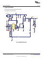
6.2 Equipment Setup
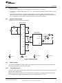
• With the power supply OFF, connect the supply to the bqTESLA™ transmitter.
• Connect the V
IN
positive power source to J1 Pin 2, and connect the negative terminal of the V
IN
source
to J1 Pin 1.
• Do not place the bqTESLA™ receiver on the transmitter. Connect a load to the receiver J3 with a
return to J4, monitor current through the load with the ammeter, and monitor the current to the load at
TP7. All voltmeters must be Kelvin connected (at the pin) to the point of interest.
6.2.1 Equipment Setup Diagram
The diagram in Figure 4 shows the test setup.
Figure 4. Equipment Setup
6.2.2 EVM Procedures
This section is provided as a guide through a few general test procedures to exercise the functionality of
the presented hardware. Some key notes follow:
6.2.2.1 Start-Up No Receiver
Turn on V
IN
, and observe that the green power LED, D1, illuminates. Status LEDs D2, D8 and D9 are OFF
until the power transfer starts.
Apply the scope probe to test point, TP18, and observe single-pulse bursts approximately every 500 ms.
This is a digital ping to begin communications with a receiver placed on the TX coil.
13
SLVUA40A–March 2014–Revised January 2015 bq500414Q bqTESLA Wireless Power TX EVM
Submit Documentation Feedback
Copyright © 2014–2015, Texas Instruments Incorporated

Test Setup
www.ti.com
6.2.2.2 Apply Receivers
Place the bq51013BEVM-764 EVM on the top of the transmitting coil. Align the centers of the receiving
and transmitting coils across each other. In the next few seconds, observe that the status LED, D6,
flashes green, indicating that communication between the transmitter and the receiver is established and
that power transfer has started.
• The status LED, D8, flashes a green light during power transfer.
• Typical output voltage is 5 V, and the output current range is 0 mA to 1 A.
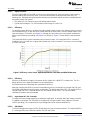
6.2.2.3 Efficiency
To measure system efficiency, measure the output voltage, output current, input voltage, and input current
and calculate efficiency as the ratio of the output power to the input power. Connect voltage meters at the
input and output of TX and RX (see Figure 4). Average the input current; the comm pulses modulate the
input current, distorting the reading. See Figure 5 for efficiency. Figure 5 shows efficiency with standard
EVM.
This shows the efficiency from transmitter input to receiver output. The input power SEPIC converter is
included in this circuit and loss is higher due to power loss in two converters. For this test, an input voltage
of 13.6 V was used.
Figure 5. Efficiency versus Power, bq500414QEVM-629 Transmitter and HPA764 Receiver
6.2.2.4 Efficiency
Efficiency is affected by changes in the power section. Higher R
DSON
MOSFET increases loss. This is a
design decision and a trade off between cost and performance.
Parts selected for the EVM design are optimized for efficiency.
Note that changing the efficiency of the unit and reducing loss (or increasing loss) changes the FOD and
the PMOD performance and may require re-calibration. This would require the FOD_CAL resistor (R52) to
change along with FOD_Threshold resistor (R3) and PMOD resistor (R22). The FOD and PMOD
calibration procedure must be repeated.
6.2.2.5 Input Power DC / DC Converter
To support the input voltage range for an automotive application, an optional wide input voltage converter
is installed on the board. The TPS40210 is configured as a Single-Ended Primary-Induction Converter
(SEPIC) providing a 12-V output from an input voltage that can be above and below 12V.
6.2.2.6 EMI Shield
The EVM is designed to support an EMI Shield above the coils to reduce emissions. The shield, PWR633,
is a comb-type filter that is effective between 100 kHz and 2 MHz.
14
bq500414Q bqTESLA Wireless Power TX EVM SLVUA40A–March 2014–Revised January 2015
Submit Documentation Feedback
Copyright © 2014–2015, Texas Instruments Incorporated

www.ti.com
Test Setup
To install the shield:
Remove clear plastic cover and hardware. Install the PWR633 filter using metal hardware provided. The
filter is grounded though the metal hardware to the TX coil area.
Circuit changes:
EMI_Shield select pin 21 ground = no shield, high(3.3V) = shield
FOD_CAL R52 no shield = 16.2 kΩ, shield = 8.06 kΩ
NOTE: if ONLY EMI behavior is to be evaluated with the addition of the shield, then circuit changes are
not required.
6.2.2.7 Configuration Resistor
Some functions can be configured by an external resistor pull up and connections, see the data sheet
(SLUSBE4) for more info:
1. Coil Select R58 and R57, configure for type of coil used
2. Shield / no shield Pin 21, configure for shield or no shield
3. Operating freq pin 26, R70 and R69, option to reduce operating range
6.2.2.8 Thermal Protection, NTC
Thermal protection is provided by an NTC resistor network is connected to pin 2. At 1 V on the sense side
(U10-2), the thermal fault is set, and the unit is shut down, The status LED, D7, illuminates red. The
system tries to restart in 5 minutes.
6.2.2.9 Foreign Object Detection
The bq500414Q EVM incorporated the Foreign Object Detection (FOD) call in WPC 1.1. Power loss is
calculated by comparing the power sent to the receiver (RX) with the power the RX reported receiving,
less know power loss. The transmitter determines the power sent to the RX by measuring input power and
calculating internal losses. The RX measures the power it received and also calculates losses. The RX
sends this information to the driver (TX) in a digital word, message packet. Unaccounted for power loss is
presumed to be a foreign object on the charging pad. Should this lost power exceed the threshold set by
R34, a FOD fault is set and power transfer is stopped.
Three key measurements for the TX FOD calculation:
• Input Power – Product of input voltage and current. Input voltage is measured at pin 45 though R33
and R31. Input current is measured using sense resistor R64 and current sense amp U9. Both
measurements must be very accurate.
• Power Loss in Transmitter – This is an internal calculation based on the operating point of the
transmitter. The calculation is adjusted using FOD_Cal resistor, R52. This calculation changes with
external component changes in the power path such as MOSFETs, resonate capacitors, and TX coil.
Recalculation of R52 and R3 is required.
• Receiver Reported Power – The receiver calculates and reports power it receives in the message
packet “Received Power Packet (0X04)”.
The FOD threshold on the EVM is set to 550 mW, R3 is set to 86.6 kΩ. Increasing R3 increases the
threshold and reduces the sensitivity to foreign objects.
This loss threshold is determined after making a measurement of transmitter performance using a FOD
calibration receiver similar to the unit manufactured by Avid
®
Technology. Contact Texas Instruments for
the FOD calibration procedure for bq500414Q.
6.2.2.10 WPC Certification
The bq500414QEVM-629 was tested and certified to WPC version 1.2.
15
SLVUA40A–March 2014–Revised January 2015 bq500414Q bqTESLA Wireless Power TX EVM
Submit Documentation Feedback
Copyright © 2014–2015, Texas Instruments Incorporated

bq500414QEVM-629 Assembly Drawings and Layout
www.ti.com
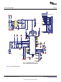
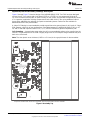
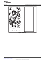
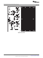
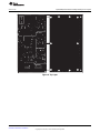
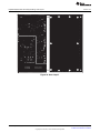
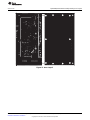
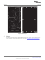
7 bq500414QEVM-629 Assembly Drawings and Layout
Figure 6 through Figure 7 show the design of the bq500414QEVM PCB. The EVM has been designed
using a 4-layer, 2-oz, copper-clad circuit board 15.24 cm × 13.335 cm, but components fit into an 8-
cm × 5.0-cm area on the top side. All parts are easy to view, probe, and evaluate the bq500414Q control
IC in a practical application. Moving components to both sides of the PCB or using additional internal
layers offers additional size reduction for space-constrained systems. Gerber files are available for
download from the EVM product folder.
A 4-layer PCB design is recommended to provide a good low-noise ground plane for all circuits. A 2-layer
PCB presents a high risk of poor performance. Grounding between the bq500414Q GND EPAD, pin 47,
36, and 32 and filter capacitor returns C19, C1, C5, and C3 should be a good low-impedance path.
Coil Grounding – A ground plane area under the coil is recommended to reduce noise coupling into the
receiver. The ground plane for the EVM is slightly larger than the coil footprint and grounded at one point
back to the circuit area.
Note: The clear plastic cover thickness (0.093 in or 2.4 mm) is the z-gap thickness for the transmitter.
Components marked ‘DNP’ should not be populated, and may not be listed in the bill of materials.
Figure 6. Assembly Top
16
bq500414Q bqTESLA Wireless Power TX EVM SLVUA40A–March 2014–Revised January 2015
Submit Documentation Feedback
Copyright © 2014–2015, Texas Instruments Incorporated


Page is loading ...
Page is loading ...
Page is loading ...
Page is loading ...
Page is loading ...
Page is loading ...
Page is loading ...
Page is loading ...
Page is loading ...
-
 1
1
-
 2
2
-
 3
3
-
 4
4
-
 5
5
-
 6
6
-
 7
7
-
 8
8
-
 9
9
-
 10
10
-
 11
11
-
 12
12
-
 13
13
-
 14
14
-
 15
15
-
 16
16
-
 17
17
-
 18
18
-
 19
19
-
 20
20
-
 21
21
-
 22
22
-
 23
23
-
 24
24
-
 25
25
-
 26
26
-
 27
27
-
 28
28
-
 29
29


Texas Instruments bq500414Q bqTESLA Wireless Power TX EVM (Rev. A) User guide
- Type
- User guide
Ask a question and I''ll find the answer in the document
Finding information in a document is now easier with AI
Related papers
-
Texas Instruments TPS82084EVM-672 Evaluation Module User guide
-
-
-
-
-
-
-
-
-
Other documents
-
Adobe AC2 User manual
-
Minka-Aire F544L-BCW User manual
-
Aptiv FM29000 User manual
-
 RES-Q 30 Amp Portable Air Compressor Installation guide
-
Aptiv SX2WPC User manual
-
 onsemi NCL31000ASGEVB LED Driver Evaluation Board User guide
-
Aptiv VOLVO User manual
-
Shenzhen View Lighting Technology CUC0603 Operating instructions
-
Linear Technology DC1967A-B Demo Manual
-
Niles nTP7-W Owner's manual

