Page is loading ...

How To Install, Operate and
Maintain Your Reverse Osmosis
System
Installation and Operation Manual
INSTALLERS: PLEASE READ ALL INSTRUCTIONS BEFORE IN-
STALLING AND USING THIS SYSTEM.
IT IS RECOMMENDED TO WAIT UNTIL THE ENTIRE SYSTEM IS
PRESSURIZED (INCLUDING STORAGE TANK & FAUCET) AND
RE-CHECK FOR ANY LEAKS BEFORE LEAVING INSTALLATION
SITE.
IT IS NORMAL FOR SOME BLACK CARBON FINES TO APPEAR
IN THE WATER WHEN EMPTYING THE FIRST 2 TANKS OF WA-
TER. THE FIRST 2 TANKS OF WATER PRODUCED SHOULD BE
EMPTIED AND NOT USED.
REVISION: 1
DATE: July 2015
80150334

2
PAGE
How Your System Works 2
Before You Start 3
Tools Needed 3
System Location 3
Parts of the System 4
Installing the Filters 4
Installing the Membrane 5
Installing the Tank Ball Valve 5
Installing the Faucet 6
Installing the Self-Piercing Inlet Saddle Valve 7
Installing the Drain Saddle 7
Installing the Unit 7
Installing Tubing Into Fittings 8
Sanitize the System 8
Installing Tubing Connections 8
Flush System and Check Operation 9
Filter Change Schedule 9
Trouble Shooting 10
Spare Parts List 10
Flow and Electrical Diagrams 11
Warranty 12
How Your System Works
For best results it is recommended to install the R/O on a COLD softened water supply.
The RO systems use four stages of treatment to filter your water:
Stage 1 - Remove sand, dirt, sediment
Stage 2 - Remove chlorine, taste & odors, very fine particulates
Stage 3 - Reduce total dissolved minerals
Stage 4 - Polish water for refined taste
The system is compact and can be installed under the sink or another convenient place close to the faucet.
The closer the proximity to the faucet the better the system flow rate.
Recommended Filter Change Schedule
Your filters require changing on a regular basis. Instructions to change them are on page 8. The schedule
below is the minimum recommendation. Depending on your water conditions the filters may need to be
changed more often.
Table of Contents
Filter Cartridges Change Schedule
Pre-filter (Sediment) Every 12 months
Pre-filter (Activated Carbon) Every 12 months
Post Filter (Activated Carbon) Every 12 months
R/O membrane Every 24-36 months

3
Before You Start
Your system contains filters which must be replaced periodically for proper operation. (Refer to Filter
Change Schedule on page 9.)
Read all steps and guides carefully before installing and using your RO system. Follow all steps exactly to
correctly install.
The system is designed to be used on potable water supplies only. If water is non-potable, additional pre-
treatment will be required.
Do not use for the treatment of water that is visually contaminated (cloudy) or has an obvious contamina-
tion source, such as contamination by raw sewage.
All plumbing should be done in accordance with local codes and requirements.
Non-Booster pump models work on water pressures of 40 psi (minimum) to 100 psi (maximum). Booster
pump models work on water pressures of 20 psi (minimum) to 100 psi (maximum). If your house water
pressure is over the maximum, install a pressure reducing valve in the water supply line to the filter system.
Do not install the system outside, or in extreme hot or cold temperatures. Temperature of the water supply
to the R/O system must be between 40°F and 100°F. Do not install on hot water.
Tools Needed
The following tools may be necessary, depending on the particular installation.
Your RO system may be installed under the sink, in a basement, or other location depending on available
space. It is recommended the system be installed in as close a proximity to the faucet to ensure optimal sys-
tem flow rate. If you have a water dispenser and or ice maker in your refrigerator, your RO system can be
installed to provide the feed water for these features but you should consult your fridge owners manual for
further information.
Guidelines for component placement are as follows:
Faucet should be placed near the sink where drinking/cooking water is normally required. A 2” flat surface is
required to mount the faucet if an existing hole for a second faucet is not available. The thickness of the
mounting surface should not exceed 1-1/4”
Storage tank may be placed where it is convenient, within ten feet of the faucet. Under the sink or in a
nearby cabinet are excellent choices. Full tanks may weigh more than thirty pounds, so a sturdy shelf is re-
quired. If tank is located further than twenty feet from the faucet, use 1/2” tubing to reduce pressure drop.
RO unit may be mounted on either side of the sink, in a cabinet or heated basement, with nearby access to
a potable, cold line and a drain.
Feed water connection is accomplished with a feed water adaptor or self-piercing inlet saddle valve. Lo-
cate this assembly as close to the R/O unit as possible. Connect to a potable, cold water supply line only.
NOTE: Softened water is preferred since it will extend the life of your R/O membrane.
Drain connection is accomplished using a waste water saddle valve which is designed to fit around a stan-
dard 1.25” - 1.50” O.D. drain pipe. The drain saddle valve should always be installed above (before) the trap
and on the vertical or horizontal tailpiece. Refer to Figure 1.
NOTE: Some local plumbing codes may require an air gap drain connection.
System Location
3/8” variable speed electric drill; 1/8”, ¼”, ½” bits
Center punch and hammer
Phillips head and flat blade screwdrivers
Adjustable wrench
Teflon tape
Plastic tube cutter

4
Parts Of The System
Installing the Filters
When handling filter cartridges be sure hands are clean and sanitized or wear surgical gloves.
1. Loosen and remove filter housings using wrench provided.
2. Remove plastic wrapper from filter cartridges. Check the o-ring to insure it is lubricated. If not,
use NSF approved silicon grease (PROVIDED). Install the o-ring into the filter housing. Install the
filters into the correct locations as indicated in Figure 1 on page 4. Insure the Carbon cartridges are
installed with the rubber gasket at the top.
3. Install and tighten the filter housings firmly by hand. Use the wrench provided to tighten an addition
1/4 to half turn. Do not over tighten.
Storage Tank (3.0 Gal)
holds filtered water, ready
for use.
Faucet (Standard) used
to dispense RO water
when needed.
Optional
air gap and designer
faucets are available.
Post-Carbon Filter is
provided for a final
“polish” to provide great
tasting drinking water.
Reverse Osmosis Membrane
reduces dissolved minerals, met-
als and salts. During the proc-
ess, harmful compounds are
separated by the membrane and
the reject water goes to drain.
Pre-Carbon Filter re-
moves chlorine in the feed
water to protect the re-
verse osmosis membrane.
Pre-filter removes larger
particles such as sand, silt,
and rust.
Self-piercing Inlet Saddle
Valve is connected to the
cold water line to supply wa-
ter to the RO system.
Drain Saddle is connected
to the drain to remove reject
water from the RO system.
Filter Housing / Mem-
brane Multi-tool used to
loosen or tighten the filter
sumps or membrane caps.
Tubing 1/4” and 3/8” tub-
ing to connect system to
tank, faucet, and drain.

5
Installing Tank Ball Valve
The RO storage tank comes with a 3/8” shut off valve that must be installed.
1. Apply 5-6 wraps of Teflon thread sealant tape to the male thread on the RO storage tank.
2. Install the shut-off valve and tighten until the gasket is compressed.
NOTES:
While there is a gasket that seals against the shut off valve, it is recommended to still use Teflon
tape on the tank threads to insure a good seal is achieved. It is also recommended to check for
any leaks after the system has had time to produce water and pressurize inside the storage tank.
Failure to do so could result in a leak that is not spotted until after the installer has left the loca-
tion.
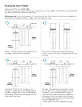
Installing the Membrane
When handling membranes be sure hands are clean and sanitized or wear surgical gloves.
1. Remove the blue quick connect clip and pull the inlet tubing to the membrane cap out.
2. Loosen and remove RO membrane cap using wrench provided.
3. Using scissors or a knife, cut the end of the plastic wrapper from the membrane. Leave it in the wrap-
per so you do not touch the membrane directly with your fingers.
4. Insert the membrane all the way into the housing.
5. Check that the o-ring is in place and install the cap onto the RO membrane housing. Tighten cap
firmly by hand. Using the wrench provided tighten an addition 1/4 to 1/2 turn.

6
Installing the Faucet
If the sink has a sprayer it may be disconnected for faucet installation. A pipe cap or plug will be necessary to
seal the sprayer connection.
The faucet should be positioned so it empties into the sink and the spout swivels freely for convenience. If
sink has a hole that can accommodate the RO faucet, no drilling is required. Proceed with mounting the fau-
cet.
Porcelain, Enamel, Ceramic on Metal or Cast Iron Sinks
For porcelain/enamel sinks marble or granite counter tops refer to Manufacturer/Supplier for proper drilling
instructions.
Installation procedures for stainless steel sinks
Recommended tools:
Center punch
Variable speed drill
High speed drill bits
Protective gloves & eye protectors
To make the faucet mounting hole (if sprayer or second hole is not used), check below to make sure the drill
does not interfere with anything below the sink. Center punch a small indent at the desired faucet location.
(2” flat surface is required, not exceeding 1-1/4” in thickness). Drill the 1/8” pilot hole. Drill the ½” hole for
the faucet shank to fit through. Clean up sharp edges.
Mounting the Faucet
1. Feed the threaded nipple through sink or counter mounting hole and orient the faucet as shown. From
below sink or counter, assemble the flat washer and hex nut on threaded nipple and tighten by hand. After
checking faucet orientation, tighten with a wrench until secure.
2. Install the faucet adaptor fitting (shown below) and tighten until the fitting bottoms out on the o-ring inside
to create the seal. Tighten with wrench until secure.
3. Insert the 3/8” tube into the quick connect fitting.

7
Installing the Self-Piercing Inlet Saddle Valve
The self-piercing saddle valve is designed for use with 3/8” to 1/2” OD soft
copper supply tubing.
1. Turn off cold water valve from under sink or main water line valve for
whole house.
2. Before installing self-piercing valve, make sure piercing lance does not
protrude beyond rubber gasket.
3. Assemble saddle valve on copper tubing.
4. Tighten screw to fasten saddle valve to copper tubing.
5. Turn handle clockwise to pierce soft copper tube until valve is firmly
seated. (Valve is closed in this position).
6. Turn on water supply to pressure cold water line and check for leaks.
Installing the Unit
When installed under a sink the unit is normally mounted to the right or left sink cabinet sidewall. It is sug-
gested to locate the system where it can be easily accessed or even removed off the hanging screws and
pulled back out from the sink to change the filters.
1. Locate the unit in the desired position. Make sure it is at least 3” off the floor. Level it and mark the loca-
tion of mounting screws.
2. Install the screws. Leave 1/4” of the screw head out from the wall.
3. Install the mounting bracket slots over the screws and hang the unit.
Installing the Drain Saddle
Prior to proceeding it is important to inspect the condition of drain pipes to
make sure they are not thin and frail. The drain saddles are designed to
be installed on standard 1-1/4” - 1-1/2” OD drain pipe.
Install drain saddle above (and before) the trap and on the vertical or hori-
zontal tailpiece. Never install it close to the outlet of a garbage disposal or
plugging of the RO drain line may result . Refer to location in Figure 1
page 4.
1. Position half of the saddle with quick connect fitting at selected location
and mark for the opening.
2. Drill 1/4” - 3/8” hole at mark through one side of pipe. Position both
halves of the saddle on drain pipe so quick connect opening lines with
hole. Add the gasket to the same side as the drilled hole.
3. Secure drain saddle clamp with bolts and nuts provided. (Do not over
tighten and make sure there is equal space between saddle halves on
each side).
Figure 2. Self-Piercing Inlet
Saddle Valve
Figure 3. Drain Saddle

8
Installing Tubing Into Fittings
Push the tube into the fitting and up to the tube stop
Pull on the tube to check that it is secure. Test the system before use.
Cut the tube square and remove burrs and sharp edges. Ensure that the
outside diameter is free from score marks. For soft or thin walled plastic
tubing we recommend the use of a tube insert.
Step 1
Step 2
Step 3
Installing Tubing Connections
With all components in place, complete final tubing
connections using these guidelines:
Tubing should follow contour of the cabinets
Cut tubing to desired length using square cuts and
proper cutting device
Make no sharp bends
Keep tubing from the post-filter to the faucet as
short as practical for good flow.
Leave enough tubing that the system can easily be
pulled out from the cabinet for easy filter changes.
Procedure (Standard Faucet)
Follow the directions on the labels installed on the
tube fittings.
1. Connect 3/8” tubing to faucet.
2. Connect ¼” tubing to drain saddle.
3. Connect 3/8” tubing storage tank.
4. Connect ¼” tubing to inlet water supply valve.
(For air gap models connect 1/4” tubing to faucet
and 3/8” tubing from faucet to drain saddle)
5. Check all connections to be sure they are secure.
6. Turn on feed water valve and check for leaks.
Sanitize System
Sanitize the System (Recommended)
Sanitizing is recommended immediately after installation of the Reverse Osmosis system. It’s also recom-
mended after servicing inner parts. It is important that the person installing or servicing the system have clean
hands while handling inner parts of the system.
1. Turn off the water supply to the RO system and close the ball valve on the storage tank.
2. Open the RO faucet.
3. Use an eyedropper (not included) and common household bleach (5.25%).
4. Add 3 ml (1 teaspoon) of bleach into open end of 3/8 tube connected to tank. Handle bleach according to
bleach manufacturer’s recommendations.
5. Connect tubing back to tank ball valve.
6. Sanitizing the system will be completed during the Flush System and Check Operation steps on the follow-
ing page.
Note: The bleach must be removed from the system before drinking the water. See Flush System
instructions on the next page.

9
Filter Change Schedule
Recommended Filter Change Schedule
The following periodic maintenance is recommended so your system will provide years of trouble-free service:
Filter Cartridges Change Schedule
Pre-filter (Sediment) Every 12 months
Pre-Carbon (Activated Carbon) Every 12 months
Post Carbon (Activated Carbon) Every 12 months
R/O membrane Every 24-36 months
To remove the filters follow the reverse procedure of the Installing the Membrane & Filter section on page 5.
To install the filters follow the instructions from the Installing the Membrane & Filter section on page 5.
Your system contains a R/O (reverse osmosis) membrane which should also be replaced periodically for proper
operation. The R/O membrane may require changing more frequently depending on the source water condi-
tions.
Flush System and Check Operation
Start-up
1. Check all connections to be sure they are secure.
2. Turn on feed water valve and check for leaks.
3. Open faucet and bleed any air out. When air is removed, close faucet, wait 5 minutes and check for leaks.
Flush System and Check Operation
1. Open faucet handle and allow tank to completely drain. Do not use this water. It is normal to see black
carbon fines in the water. They need to be flushed out of the new carbon filter. (When tank is empty, fau-
cet will steadily drip. This is the rate the R/O system processes water).
2. Close faucet. Allow system (including storage tank) to pressurize for 15 minutes and re-inspect system for
leaks.
3. Allow system to process water for approximately 1 hour, at which point tank will be practically full.
4. Open faucet again and allow tank to empty for a second time. It is normal to see some black carbon fines
in the water. Do not use this water.
5. Wait another four hours to allow tank to re-fill.
NOTE: If no objectionable tastes or black carbon fines are noticed after second tank draining, RO processed
water is ready for use. Otherwise, drain tank and re-fill for a third time
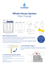
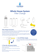
Change Membrane Procedure
1. Turn off water supply by turning handle on self-
piercing inlet saddle valve clockwise until valve is
fully closed.
2. Turn storage tank valve clockwise to close.
3. Open faucet to relieve pressure.
4. Remove the blue quick connect clip and pull the
inlet tubing to the membrane cap out.
5. Loosen and remove RO membrane cap using
wrench provided.
6. Using scissors or a knife, cut the end of the plastic
wrapper from the membrane. Leave it in the wrap-
per so you do not touch the membrane directly
with your fingers.
7. Insert the membrane all the way into the housing.
8. Check that the o-ring is in place and install the cap
onto the RO membrane housing. Tighten cap
firmly by hand. Using the wrench provided tighten
an addition 1/4 to 1/2 turn.
9. Turn water supply back on.
10.Turn storage tank valve to open position.
11.Close faucet.
12.Empty storage tank. Produce an additional full
tank of water and discard it. Normal operation can
resume.
NOTE: It is normal for the post carbon filter to add a
small amount of TDS back into the product water
so to get an accurate TDS measurement take the
sample directly after the membrane housing ahead
of the post filter.

10
Trouble Shooting
PROBLEM CAUSE SOLUTION
No product water. 1. Water supply is turned off. 1. Turn on feed water.
1. Water supply is blocked. 1. Clear restriction.
2. Filters are plugged. 2. Replace pre-filter cartridge (s).
3. Feed water valve plugged or closed. 3. Open valve or unclog.
4. No drain flow. Drain flow restrictor is
plugged.
4. Clear or replace Flow Restrictor
5. Drain saddle plugged. 5. Clear restriction.
1. Low feed water pressure. 1. Check source water supply.
2. No power supply or loose connection. 2. Turn on power supply.
3. Transformer burnt out. 3. Replace.
1. Carbon pre-filter plugged. 1. Replace filter cartridge.
2. Inlet solenoid valve not working. 2. Repair or replace solenoid valve.
System does not shut off. 1. High pressure switch not working. 1. Repair or replace high pressure switch.
Abnormal pump cycling noise. 1. Pre-filter plugged or low feed water pressure.
1. Replace filter or adjust or sufficient feed
water.
No water to drain. 1. Plugged drain flow restrictor. 1. Replace drain flow restrictor.
Water has bad taste. 1. Post filter (CB-10) is exhausted. 1. Replace post filter
1. Tubing connections not installed properly. 1. Re-install tubing into fitting.
2. Defective tubing. 2. Cut damage section of tubing and re-install.
Not enough product water.
Pump not running.
Pump running but system not
producing water.
Leaks
Spare Parts List - RO 75 GPD 4 STAGE
No. PART No. Description Material Quantity
1 41320004
CARTRIDGE HOUSING-10
PP 3
2 65010001
PRE-CARBON FILTER CARTRIDGE
10'' 1
3 65010009
SEDIMENT FILTER CARTRIDGE
10'',5 μm PP 1
4 41318002
CONNECT TUBE
PP 1
5 41320003
HOUSING CAP
PP 3
6 70030011
SELF PIERCING INLET SADDLE VALVE
1/4'' 1
7 42005015
UNION ELBOW 1/4
1/4''O.D 2
8 41510001
LOCK CLIP
4
9 41323003
MALE CONNECTOR 1/4
POM 2
10 70020002
TANK 3.0 GALLON
1
11 65030032
DRAIN SADDLE
1/4''O.D*1.5'' 1
12 80010503
3/8'' QC ball valve
1
13 41504012
BRACKET BNT-RO75-C31
1
14 41209016
FLOW CONTROL 450ML/MIN
1
15 42005014
UNION ELBOW 1/4
1/4''O.D POM 3
16 41323005
CLIP
Φ9.8*81.8,POM 3
17 41320008
RO MEMBRANE HOUSING CAP
PP 1
18 41804004
RO HOUSING CAP ORING
EPDM 1
19 41901007
RO MEMBRANE
1812 1
20 41320007
RO MEMBRANE HOUSING
PP 1
21 41323002
LARGE SINGLE CLAMP
PP 2
22 42005016
PRODUCT WATER CHECK VALVE
3/8''O.D*3/8''O.D 1
23 70040001
GOOSENECK FAUCET
1
24 41323007
MALE CONNECTOR 3/8''
POM 2
25 42005045
CLIP 3/8''
3/8''O.D 2
26 42005036
RO SHUITOFF VALVE 1/4'' QC
POM 1
27 41804003
CARTRIDGE HOUSING ORING
EPDM 3
28 65010001
POST CARBON FILTER CARTRIDGE
1
RO 75 GPD 4 STAGE

11
Spare Parts List - RO 75 GPD 4 STAGE BP
No PART No Description Material Quantity
1 41320004
CARTRIDGE HOUSING-10
PP 3
2 65010001
SEDIMENT FILTER CARTRIDGE
10'',5 μm PP 1
3 41804003
CARTRIDGE HOUSING ORING
EPDM 3
4 70020002
TANK 3.0 GALLON
1
5 70030011
SELF PIERCING INLET SADDLE VALVE
1/4'' 1
6 80010503
3/8'' QC ball valve
1
7 42005015
UNION ELBOW 1/4
1/4''O.D 2
8 41320003
HOUSING CAP
PP 3
9 41510001
LOCK CLIP
4
10 65030032
DRAIN SADDLE
1/4''O.D*1.5'' 1
11 41318002
CONNECT TUBE
PP 1
12 41504002
BRACKET BNT-RO75-C04
1
13 41213003
POWER TRANSFORMER 24V 2.0A
24V 2.0A 1
14 41210001
LOW PRESSURE SWITCH
1/4'' 1
15 41210002
HIGH PRESSURE SWITCH
1/4'' 1
16 41209002
INLET SOLENOID VALVE
1
17 42005014
UNION ELBOW 1/4
1/4''O.D POM 3
18 41320008
RO MEMBRANE HOUSING CAP
PP 1
19 41804004
RO HOUSING ORING
EPDM 1
20 41901007
RO MEMBRANE
1812 1
21 41320007
RO MEMBRANE HOUSING
PP 1
22 41203005
CONTROLLER
1
23 41323002
LARGE SINGLE CLAMP
PP 2
24 41209004
SOLENOID VALVE / 420ML/MIN
1
25 41317002
CONTROL BOX
pp 1
26 42005016
PRODUCT WATER CHECK VALVE
3/8''O.D*3/8''O.D 1
27 41208004
PUMP
75G 1
28 70040001
FAUCET
1
29 42005016
UNION ELBOW 3/8''
3/8''O.D 2
30 65010001
PRE CARBON FILTER CARTRIDGE
10'' 1
31 65010001
POST CARBON FILTER CARTRIDGE
10'' 1
RO 75 GPD 4 STAGE BP
PRE SEDIMENT
Flow And Electrical Diagrams
RO 75 GPD 4 STAGE
RO 75 GPD 4 STAGE BP
Wiring Diagram RO 75 GPD 4 STAGE BP
TO DRAIN
INLET
PRE CARBON
POST CARBON
3.0 GAL
TANK
RO MEMBRANE
TO FAUCET
PRE SEDIMENT
PRE CARBON
3.0 GAL
TANK
POST CARBON
RO MEMBRANE
TO FAUCET
INLET
TO DRAIN
AUTO SHUT-OFF
450 ML/MIN FLOW
CONTROL
LOW PRESSURE SWITCH
SOLENOID VALVE
420 ML/MIN SOLENOID
VALVE / FLOW CONTROL
CHECK VALVE
TANK FULL
PRESSURE SWITCH
CHECK VALVE
PUMP
Feed Water Guidelines
Maximum TDS 2000 ppm
Hardness < 7gpg
Iron (Fe) <0.2 ppm
Manganese (Mn) <0.05 ppm
Hydrogen Sulfide 0.0 ppm
Turbidity <1.0 NTU
Feed Water Pressure 40-100 psi
Temperature 40-100° F
pH Range 3.0 - 11.0

12
Warranty
Canature WaterGroup™ RO Systems (excluding cartridge filters and membrane) are
warranted to be free from defects in materials and workmanship under normal use
within the operation specifications for a period of two (2) years from the date of
manufacture or date of pur-chase when verified by a bill of sale.
Canature WaterGroup™ will replace any part which fails two (2) years from date of
manufacture as indicated by the serial number or date code, provided the failure is due to a
defect in material or workmanship. The only exception shall be when proof of purchase
or installation is provided and then the warranty period shall be from the date thereof.
Canature WaterGroup™ assumes no responsibility for consequential damage, labour or
expense incurred as a result of a defect or for failure to meet the terms of these
guarantees because of circumstances beyond its control.
Canature WaterGroup™
655 Park Street
Regina, SK. S4N 5N1
Canada
Toll Free: (877) 299-5999
9760 Mayflower Park Drive, Suite 110
Carmel, IN. 46032
USA
Toll Free: (800) 354-7867
/