Page is loading ...

INSTRUCTION MANUAL
AirLink® Raven RV50 4G LTE
Sierra Wireless® Cellular Modem
Revision: 3/16
Copyright © 2016
Campbell Scientific, Inc.


Limited Warranty
“Products manufactured by CSI are warranted by CSI to be free from defects in
materials and workmanship under normal use and service for twelve months
from the date of shipment unless otherwise specified in the corresponding
product manual. (Product manuals are available for review online at
www.campbellsci.com.) Products not manufactured by CSI, but that are resold
by CSI, are warranted only to the limits extended by the original manufacturer.
Batteries, fine-wire thermocouples, desiccant, and other consumables have no
warranty. CSI’s obligation under this warranty is limited to repairing or
replacing (at CSI’s option) defective Products, which shall be the sole and
exclusive remedy under this warranty. The Customer assumes all costs of
removing, reinstalling, and shipping defective Products to CSI. CSI will return
such Products by surface carrier prepaid within the continental United States of
America. To all other locations, CSI will return such Products best way CIP
(port of entry) per Incoterms ® 2010. This warranty shall not apply to any
Products which have been subjected to modification, misuse, neglect, improper
service, accidents of nature, or shipping damage. This warranty is in lieu of all
other warranties, expressed or implied. The warranty for installation services
performed by CSI such as programming to customer specifications, electrical
connections to Products manufactured by CSI, and Product specific training, is
part of CSI's product warranty. CSI EXPRESSLY DISCLAIMS AND
EXCLUDES ANY IMPLIED WARRANTIES OF MERCHANTABILITY
OR FITNESS FOR A PARTICULAR PURPOSE. CSI hereby disclaims,
to the fullest extent allowed by applicable law, any and all warranties and
conditions with respect to the Products, whether express, implied or
statutory, other than those expressly provided herein.”

Assistance
Products may not be returned without prior authorization. The following
contact information is for US and international customers residing in countries
served by Campbell Scientific, Inc. directly. Affiliate companies handle repairs
for customers within their territories. Please visit www.campbellsci.com to
determine which Campbell Scientific company serves your country.
To obtain a Returned Materials Authorization (RMA), contact CAMPBELL
SCIENTIFIC, INC., phone (435) 227-9000. After an application engineer
determines the nature of the problem, an RMA number will be issued. Please
write this number clearly on the outside of the shipping container. Campbell
Scientific’s shipping address is:
CAMPBELL SCIENTIFIC, INC.
RMA#_____
815 West 1800 North
Logan, Utah 84321-1784
For all returns, the customer must fill out a “Statement of Product Cleanliness
and Decontamination” form and comply with the requirements specified in it.
The form is available from our website at www.campbellsci.com/repair. A
completed form must be either emailed to repair@campbellsci.com or faxed to
(435) 227-9106. Campbell Scientific is unable to process any returns until we
receive this form. If the form is not received within three days of product
receipt or is incomplete, the product will be returned to the customer at the
customer’s expense. Campbell Scientific reserves the right to refuse service on
products that were exposed to contaminants that may cause health or safety
concerns for our employees.

Safety
DANGER — MANY HAZARDS ARE ASSOCIATED WITH INSTALLING, USING, MAINTAINING, AND WORKING ON OR AROUND
TRIPODS, TOWERS, AND ANY ATTACHMENTS TO TRIPODS AND TOWERS SUCH AS SENSORS, CROSSARMS, ENCLOSURES,
ANTENNAS, ETC. FAILURE TO PROPERLY AND COMPLETELY ASSEMBLE, INSTALL, OPERATE, USE, AND MAINTAIN TRIPODS,
TOWERS, AND ATTACHMENTS, AND FAILURE TO HEED WARNINGS, INCREASES THE RISK OF DEATH, ACCIDENT, SERIOUS
INJURY, PROPERTY DAMAGE, AND PRODUCT FAILURE. TAKE ALL REASONABLE PRECAUTIONS TO AVOID THESE HAZARDS.
CHECK WITH YOUR ORGANIZATION'S SAFETY COORDINATOR (OR POLICY) FOR PROCEDURES AND REQUIRED PROTECTIVE
EQUIPMENT PRIOR TO PERFORMING ANY WORK.
Use tripods, towers, and attachments to tripods and towers only for purposes for which they are designed. Do not exceed design limits.
Be familiar and comply with all instructions provided in product manuals. Manuals are available at www.campbellsci.com or by
telephoning (435) 227-9000 (USA). You are responsible for conformance with governing codes and regulations, including safety
regulations, and the integrity and location of structures or land to which towers, tripods, and any attachments are attached. Installation
sites should be evaluated and approved by a qualified engineer. If questions or concerns arise regarding installation, use, or
maintenance of tripods, towers, attachments, or electrical connections, consult with a licensed and qualified engineer or electrician.
General
• Prior to performing site or installation work, obtain required approvals and permits. Comply
with all governing structure-height regulations, such as those of the FAA in the USA.
• Use only qualified personnel for installation, use, and maintenance of tripods and towers, and
any attachments to tripods and towers. The use of licensed and qualified contractors is highly
recommended.
• Read all applicable instructions carefully and understand procedures thoroughly before
beginning work.
• Wear a hardhat and eye protection, and take other appropriate safety precautions while
working on or around tripods and towers.
• Do not climb tripods or towers at any time, and prohibit climbing by other persons. Take
reasonable precautions to secure tripod and tower sites from trespassers.
• Use only manufacturer recommended parts, materials, and tools.
Utility and Electrical
• You can be killed or sustain serious bodily injury if the tripod, tower, or attachments you are
installing, constructing, using, or maintaining, or a tool, stake, or anchor, come in contact with
overhead or underground utility lines.
• Maintain a distance of at least one-and-one-half times structure height, 20 feet, or the distance
required by applicable law, whichever is greater, between overhead utility lines and the
structure (tripod, tower, attachments, or tools).
• Prior to performing site or installation work, inform all utility companies and have all
underground utilities marked.
• Comply with all electrical codes. Electrical equipment and related grounding devices should be
installed by a licensed and qualified electrician.
Elevated Work and Weather
• Exercise extreme caution when performing elevated work.
• Use appropriate equipment and safety practices.
• During installation and maintenance, keep tower and tripod sites clear of un-trained or non-
essential personnel. Take precautions to prevent elevated tools and objects from dropping.
• Do not perform any work in inclement weather, including wind, rain, snow, lightning, etc.
Maintenance
• Periodically (at least yearly) check for wear and damage, including corrosion, stress cracks,
frayed cables, loose cable clamps, cable tightness, etc. and take necessary corrective actions.
• Periodically (at least yearly) check electrical ground connections.
WHILE EVERY ATTEMPT IS MADE TO EMBODY THE HIGHEST DEGREE OF SAFETY IN ALL CAMPBELL SCIENTIFIC PRODUCTS,
THE CUSTOMER ASSUMES ALL RISK FROM ANY INJURY RESULTING FROM IMPROPER INSTALLATION, USE, OR
MAINTENANCE OF TRIPODS, TOWERS, OR ATTACHMENTS TO TRIPODS AND TOWERS SUCH AS SENSORS, CROSSARMS,
ENCLOSURES, ANTENNAS, ETC.


i
Table of Contents
PDF viewers: These page numbers refer to the printed version of this document. Use the
PDF reader bookmarks tab for links to specific sections.
1. Introduction ................................................................ 1
2. Precautions ................................................................ 1
3. Initial Inspection ......................................................... 1
3.1 Ships With List .................................................................................... 2
4. QuickStart ................................................................... 2
4.1 Establish Cellular Service .................................................................... 2
4.1.1 Verizon Wireless ........................................................................... 2
4.1.2 AT&T ........................................................................................... 3
4.2 Install the SIM Card ............................................................................. 3
4.3 Configure RV50 ................................................................................... 4
4.4 Set up LoggerNet ................................................................................. 6
4.5 Set Up Hardware .................................................................................. 8
4.6 Test the Connection ............................................................................. 8
5. Overview ..................................................................... 9
6. Specifications ............................................................. 9
6.1 RV50 Specifications ............................................................................ 9
7. Installation ................................................................ 10
7.1 Base Station Requirements for RV50 ................................................ 10
7.2 Datalogger Site Equipment ................................................................ 11
7.3 RV50 Mounting Kit (pn 32252) ......................................................... 14
7.3.1 Mounting the RV50 Flat on the Back Plane ............................... 14
7.3.2 Mounting the RV50 on Edge to the Back Plane ......................... 15
7.4 Wiring and Connections ..................................................................... 15
7.4.1 Modem Communication Connections ........................................ 16
7.4.2 Modem Power Connections ........................................................ 17
7.4.3 Antenna Connection.................................................................... 17
7.5 ACEmanager and Template Files ...................................................... 18
7.6 Enabling PPP Mode ........................................................................... 20
8. Operation .................................................................. 22
8.1 Ports ................................................................................................... 22
8.2 LED Indicator Lights ......................................................................... 22
8.3 Rebooting the RV50........................................................................... 23
8.4 Reset the RV50 to Factory Default Settings ...................................... 23
9. Attributions ............................................................... 23

Table of Contents
ii
Appendices
A. Controlling Power to the RV50 .............................. A-1
B. EmailSend Using the Gmail™ Outgoing SMTP
Server.................................................................... B-1
B.1 Setting up a Gmail Account ............................................................ B-1
B.2 Sending to Multiple Addresses ........................................................ B-2
B.3 Sending a Text Message to a Phone ................................................ B-2
B.4 EmailSend Program Example ......................................................... B-2
C. Configuring the RV50 for Dynamic IP ................... C-1
D. Using the RV50 Ethernet Port ............................... D-1
E. Regulatory Information .......................................... E-1
E.1 Important Information for North American Users............................ E-1
E.2 RF Exposure ..................................................................................... E-1
E.3 EU .................................................................................................... E-2
E.4 Declaration of Conformity ................................................................ E-2
E.5 RoHS Compliance ............................................................................ E-3
Figures
4-1. SIM Card Installation .......................................................................... 4
7-1. Antennas for Use with the RV50 Modem ......................................... 13
7-2. RV50 Mounting Options ................................................................... 14
7-3. Flat Mount ......................................................................................... 15
7-4. Edge Mount ....................................................................................... 15
7-5. RS-232 Connection ........................................................................... 16
7-6. CR6 RS-232 Connection ................................................................... 16
7-7. Ethernet Connection .......................................................................... 16
7-8. CS I/O Connection ............................................................................ 16
7-9. Antenna Connection .......................................................................... 17
C-1. Serial Server Mode with Dynamic IP .............................................. C-3
Tables
4-1. Template Files ..................................................................................... 6
7-1. Power Connections ............................................................................ 17
7-2. AceManager Template Files ............................................................. 19
8-1. LED Indicator Lights......................................................................... 22
CRBasic Examples
A-1. Using TimeIsBetween to Turn On and Off SW12 .......................... A-1
A-2. Using If Statements to Turn On and Off SW12 .............................. A-2
B-1. Using EmailSend to Send a Text Message ...................................... B-2

1
AirLink® Raven RV50 4G LTE
Sierra Wireless® Cellular Modem
1. Introduction
This manual provides information for interfacing the AirLink® Raven RV50
cellular modem to Campbell Scientific dataloggers.
The RV50 digital cellular modem is manufactured by Sierra Wireless® and
supports network operator switching based on the SIM for use on GSM (Global
System for Mobile Communications) and CDMA (Code Division Multiple
Access) networks. The modem is accessed through the Internet using TCP/IP
communications protocol.
Use of the RV50 requires a Verizon® CDMA/1xRTT/EVDO/LTE or AT&T®
GSM/GPRS/EDGE/HSPA+/LTE business account or an equivalent account
from another service provider. See Section 4.1, Establish Cellular Service
(p. 2),
for more information.
For additional information on the RV50 modem, see the Support section of the
Sierra Wireless website.
Before using the RV50, please study:
• Section 2, Precautions
(p. 2)
• Section 3, Initial Inspection
(p. 1)
• Section 4, QuickStart
(p. 2)
2. Precautions
• READ AND UNDERSTAND the Safety section at the front of this
manual.
• CAUTION: This device uses considerably more power than the datalogger
(see Section 6, Specifications
(p. 9)) and may require a larger power supply,
switching power with the datalogger, or a combination of these to ensure
the battery is not drained. See Appendix A, Controlling Power to the RV50
(p. A-1), for program examples of using switched 12V to control power to
the RV50.
3. Initial Inspection
• Upon receipt of the RV50, inspect the package and contents for damage.
File any damage claims with the shipping company.
• Immediately check package contents against the shipping documentation
(see Section 3.1, Ships With List
(p. 2)). Contact Campbell Scientific about
any discrepancies.

AirLink® Raven RV50 4G LTE Sierra Wireless® Cellular Modem
2
3.1 Ships With List
• (1) grey power cable (from original manufacturer)
• (4) screws and washers (from original manufacturer)
• (1) 2 ft Ethernet cable
• (1) Quick Start Guide
• (1) ResourceDVD
4. QuickStart
4.1 Establish Cellular Service
The RV50 supports network operator switching based on the inserted SIM.
This means that the same modem can be configured for either Verizon
Wireless® (CDMA), AT&T® (GSM) or other supported CDMA and GSM
networks.
4.1.1 Verizon Wireless
What you need:
• Verizon Wireless CDMA/1xRTT/EVDO/LTE coverage at the
datalogger site. For a coverage map, refer to:
www.verizonwireless.com/landingpages/better-matters/#maps
• CDMA/1xRTT/EVDO/LTE static unrestricted IP account established
with Verizon Wireless.
Generally, there is a $500 one-time-per-customer charge to
activate static IP on the account. Additional static IP lines of
service may be added at no additional charge from that time on.
To set up an account, you will need the IMEI number of the modem. The IMEI
number is listed on a label on the modem and also on the box. To set up an
account with Verizon Wireless, call:
888-384-1775 for Business Sales
800-256-4646 for Personal Sales
Verizon Wireless will provide a Subscriber Identity Module (SIM) card for
each modem. The mini-SIM (2FF) card must be installed inside of the modem
as described in Section 4.2, Install the SIM Card
(p. 3). In addition to the SIM
card, you should receive:
• 10-digit MSISDN number (telephone number associated with the
SIM, used for billing)
• IP Address for a static IP account and an APN for
CDMA/1xRTT/EVDO/LTE service. A common APN used for this
application is: we01.VZWSTATIC. The user must program the APN
name into the modem as described in Section 4.3, Configure RV50
(p. 4).
NOTE

AirLink® Raven RV50 4G LTE Sierra Wireless® Cellular Modem
3
4.1.2 AT&T
What you need:
• AT&T GSM/GPRS/EDGE/HSPA+/LTE coverage at the datalogger
site (for a coverage map refer to: www.att.com/maps/wireless-
coverage.html)
• GSM/GPRS/EDGE/HSPA+/LTE business account established with
AT&T
To set up a GSM/GPRS/EDGE/HSPA+/LTE business account, contact your
AT&T Business Account Representative or Blu-Telecommunications.
Blu-Telecommunications is part of the Alliance Channel with AT&T and can
assist any customer nationwide. Blu-Telecommunications will contact AT&T
and work with an AT&T account manager to set up an account.
Contact information for Blu-Telecommunication:
Phone number: (877) 422-2616, or Email box: i2gold@blu-tel.com
What to ask for: M2M Setup
Who to ask for: Carlos Morales or Andy Tran
An Access Point Name (APN) must be added onto the account to make the
modem accessible through the Internet. For networks with fewer than 30
modems, the standard ‘I2Gold APN’ can be used; networks with more than 30
modems will require a ‘Custom APN’. A Custom APN has a set-up fee starting
at $500 and takes a minimum of 7 to 14 business days to complete. The user
must program the APN name into the modem as described in Section 4.3,
Configure RV50
(p. 4).
AT&T will provide a Subscriber Identity Module (SIM) card for each modem.
The mini-SIM (2FF) card must be installed inside of the modem as described
in Section 4.2, Install the SIM Card
(p. 3). In addition to the SIM card, you
should receive:
• 10-digit MSISDN number (telephone number associated with the
SIM, used for billing)
• IP Address and APN for GSM/GPRS/EDGE/HSPA+/LTE service
4.2 Install the SIM Card
The SIM in the RV50 is a smartcard that securely stores the key identifying a
mobile subscriber. You will only need to install the SIM once in the life of the
modem.
To install the mini-SIM (2FF) card:
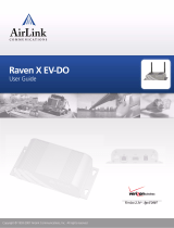
1. Remove the SIM card cover.
2. By default, the upper slot is the primary SIM. Note the location of the
notched corner for correct alignment. The gold contact points of the SIM
face down when inserting into the upper slot as shown in FIGURE 4-1.
(They face up when inserting into the lower slot.) Gently slide the card

AirLink® Raven RV50 4G LTE Sierra Wireless® Cellular Modem
4
into the upper slot until it stops and locks into place. To eject the SIM
card, press it in slightly and then release.
3. Replace the SIM card cover.
FIGURE 4-1. SIM Card Installation
4.3 Configure RV50
QuickStart describes configuring the RV50 in serial server mode.
It may also be configured in Point-to-Point Protocol (PPP) mode.
For a description of the modes, see Section
5, Overview (p. 9). For
instructions on setting up the RV50 in PPP mode, see Section 7.5,
ACEmanager and Template Files
(p. 18), and Section 7.6, Enabling
PPP Mode
(p. 20).
The RV50 is configured using ACEmanager, a web based configuration tool
hosted by the RV50. ACEmanager can be accessed using Internet Explorer® or
Firefox® remotely over the cellular WAN or locally over Ethernet. A number
of templates will be provided for download to make most configurations very
simple once connected to ACEmanager.
1. Connect the Cellular antenna.
2. Connect the Diversity antenna, if used. Recommended but not required.
Note: If a Diversity antenna is not used, use ACEmanager to disable
WAN/Cellular RX Diversity.
NOTE

AirLink® Raven RV50 4G LTE Sierra Wireless® Cellular Modem
5
3. Connect the power cable leads to a power supply.
Lead Color Function Connect To
Black Ground G
White Enable (On/Off) 12V or SW12V or C Port for Control
Red Power (10 to 36 V) 12V
4. Connect the power cable to the RV50 DC Power input. When the RV50 is
properly set up and powered, the status LEDs will turn on. The RV50 will
then begin the activation/provisioning process and attempt to connect to
the mobile network. This process typically takes 5 to 10 minutes. A
successful connection is indicated by a solid green or solid amber
Network LED. If the RV50 does not automatically connect to the
network, you may need to proceed to Configuration (Step 6) to confirm or
enter your WAN/Cellular APN information.
5. Download Campbell Scientific’s collection of configuration templates
from www.campbellsci.com/downloads and run the executable
downloaded. The templates can also be found on the Campbell Scientific
ResourceDVD.
6. Connect your Windows® computer to the RV50 using the supplied
Ethernet cable.
7. Launch an Internet Explorer or Firefox web browser, and enter
http://192.168.13.31:9191 into the address bar. The ACEmanager login
screen should appear in your browser.
8. Log in using User Name = user and Password = 12345
8. Once logged in, check the Status Network State field. It should read
Network Ready, indicating the RV50 is connected to the cellular network.

AirLink® Raven RV50 4G LTE Sierra Wireless® Cellular Modem
6
You can easily test the RV50 connection to the Internet by selecting the
Admin / Advanced tab and using the PING tool to ping an Internet
server, such as www.campbellsci.com.
9. Click the Template menu button in the ACEmanager toolbar. A template
application window will appear. Browse to and upload one of the
configuration templates downloaded from Campbell Scientific.
TABLE 4-1. Template Files
Template File Name Description
RV50_115200.xml
Default configuration with RS-232 at 115200
baud and Ethernet communication enabled.
RV50_9600.xml
Default configuration with RS-232 at 9600 baud
and Ethernet communication enabled.
10. Reboot the RV50 after successfully applying the configuration template.
You can do this by clicking the Reboot button on the ACEmanager
toolbar, by momentarily pressing the Reset button (2 sec), or by
temporarily removing power from the RV50.
4.4 Set up LoggerNet
The LoggerNet Network Map is configured from the LoggerNet Setup screen.
Setup has two options, EZ (simplified) and Standard. Click on the
View menu at the top of the Setup screen, and select Standard
view.
From the LoggerNet toolbar, click Main | Setup and configure the Network
Map as described below.
1. Select Add Root | IPPort.
2. Add a datalogger to the IPPort (PakBus® dataloggers, for example the
CR1000, require a PakBusPort).
3. Select the IPPort in the Network Map. Enter the RV50 IP address (or
domain name) and port number. The IP address and port number are input
in the Internet IP Address field separated by a colon. Preceding zeros are
not entered in the Internet IP Address (for example, 070.218.074.247 is
entered as 70.218.74.247). DevConfig and the RV50 template file
configure the port number to 3001 for serial server mode. Set the Extra
Response Time to 4 seconds.
Example settings for a static IP address:
NOTE

AirLink® Raven RV50 4G LTE Sierra Wireless® Cellular Modem
7
4. For PakBus dataloggers, leave the default settings for the PakBusPort.
PakBus Port Always Open should not be checked.

AirLink® Raven RV50 4G LTE Sierra Wireless® Cellular Modem
8
5. For PakBus dataloggers, set the PakBus Address to match that of the
datalogger (default address in the datalogger is 1). Click Apply to save the
changes.
4.5 Set Up Hardware
The simplest hardware setup for modern dataloggers is to connect a null
modem cable (CSI pn 18663) between the RS-232 ports of the datalogger and
the RV50. See Section 7.4, Wiring and Connections
(p. 15).
4.6 Test the Connection
After the Network Map has been configured, test the cellular connection using
the Connect screen as shown below. Click on the appropriate station and click
Connect to initiate a call to the datalogger. If the call is successful, the
connectors at the bottom of the screen will come together and clock
information from the datalogger will be displayed in the Station Date/Time
field. If the connection fails, a Communications Failure message will be
displayed.

AirLink® Raven RV50 4G LTE Sierra Wireless® Cellular Modem
9
5. Overview
The RV50 modem may be configured in one of two ways, depending on the
communications type and needs of the user. For many applications that just
need a connection for data collection and datalogger maintenance or
monitoring, setup as a serial server is sufficient. In this mode, the modem
receives IP communications over the cellular network and converts those to
serial (RS-232) communications to pass on to the datalogger. From the
datalogger’s perspective, this is no different than a serial cable connecting it to
a PC. Section 4, QuickStart
(p. 2), describes setting up the RV50 in serial server
mode.
Alternatively, if IP communications are needed on the datalogger, the modem
may be set up in Point-to-Point Protocol (PPP) mode. In this mode, the modem
simply passes IP communications directly to the datalogger. This enables
features such as FTP, HTTP, and emailing. For information on configuring the
RV50 in PPP mode, see Section 7.5, ACEmanager and Template Files
(p. 18),
and Section 7.6, Enabling PPP Mode
(p. 20). See Appendix B, EmailSend Using
the Gmail™ Outgoing SMTP Server
(p. B-1), for more information on emailing.
6. Specifications
6.1 RV50 Specifications
Sierra Wireless® AirLink® RV50 cellular modem (MC7354 radio module)
Cellular WAN
• Network Technology: 4G with automatic fallback to 3G and 2G
• Cellular WAN: North American Model
o Carrier Approvals: Verizon®, AT&T®, Sprint®, T-Mobile®
USA, Rogers™, Bell®, Telus®
o LTE: 1900(B2), AWS(B4), 850(B5), 700(B13), 700(B17),
1900(B25)
o WCDMA: 2100(B1), 1900(B2), AWS(B4), 850(B5), 900(B8)

AirLink® Raven RV50 4G LTE Sierra Wireless® Cellular Modem
10
o EV-DO/CDMA: 800(BC0), 1900(BC1), 1700(BC10)
o GSM/GPRS/EDGE: Quad-band
o Industry Approvals: FCC, IC, PTCRB
o Software defined radio with automatic network operator
switching
o Dual SIM Interfaces
Host Interfaces
• 10/100/1000 RJ45 Ethernet
• RS-232 serial port, DB9 female
• USB version 2.0 with micro-B connector
RF Connectors
• 3 SMA antenna connectors (primary, diversity & GPS)
• Active antenna support
Power
• Operating Voltage: 7 to 36 Vdc
• Typical Enable/Ignition Sense Line Low: 1 mA @ 12V
• Typical Idle: 65 to 95 mA @ 12V, depending on configuration
• Typical Active: 250 to 300 mA @ 12V, depending on configuration
Size
• Dimensions: 119 mm x 34 mm x 94 mm (4.69 in x 1.34 in x 3.7 in)
• Weight: 320 g (11.3 oz)
Environmental
• Operating Temperature Range: –30 to 70 °C (–22 to 158 °F)
• Storage Temperature: –40 to 85 °C (–40 to 185 °F)
• Humidity: 90% @ 60 °C
• Military Specification : MIL-STD-810 conformance to thermal,
mechanical shock, and humidity
• IP64 rated ingress protection
Industry Certifications
• Safety: IECEE Certification Bodies Scheme (CB Scheme), UL60950
• Vehicle Usage: E-Mark (UN ECE Regulation 10.04),ISO7637-2, SAE
J1455 (Shock & Vibration)
• Hazardous Environments: Class 1 Div 2
• Environmental: RoHS, REACH, WEEE
7. Installation
7.1 Base Station Requirements for RV50
PC running Campbell Scientific’s LoggerNet or PC400 software with access to
the Internet.

AirLink® Raven RV50 4G LTE Sierra Wireless® Cellular Modem
11
7.2 Datalogger Site Equipment
• RV50 modem with power cable (included with modem).
• Datalogger — CR2XX, CR300 Series, CR1000, CR5000, CR3000, CR800
Series, CR6 Series.
• Modem Interface
If connecting to RS-232 port:
Null Modem Cable (pn 18663) — connects the modem to the
CR3000, CR800, CR2XX, CR300 Series, CR1000, or CR5000
RS-232 port.
CPI/RS-232 RJ45 to DB9 Cable (pn 31055) — connects the
modem to the CR6 CPI/RS-232 port
If connecting to CS I/O port:
SC105 Interface — any current datalogger with a CS I/O port.
The SC105 must be configured for use with the modem using
DevConfig. Settings should be:
CS I/O Mode: SDC Address 7, 8, 10, or 11
RS-232 Mode: Modem
Baud Rate: 115.2K or 9600 baud depending on datalogger model
8 data bits, 1 stop bit, no parity
If connecting to Ethernet port:
Ethernet Cable (pn 28899) – connects the modem to the CR6 or
NLxxx.
• RV50 Mounting Kit (pn 32252) — includes mounting hardware for
securing the modem to below-referenced environmental enclosure.
• Antenna — the following antennas are available from Campbell Scientific.
Contact a Campbell Scientific application engineer for help in determining
the best antenna for your application.
o The 20679 is a dual-band, omnidirectional antenna for our CDMA
and GPRS/EDGE digital-cellular modems. It covers both the 800-
MHz band and the 1.9-GHz band. For the 800-MHz band, the 20679
provides a 0-dBd gain. For the 1.9-GHz band, the 20679 provides a 3-
dBd gain. This antenna is recommended for locations where cellular
coverage is strong.
The 20679 includes a mount/U-bolt assembly that allows the antenna
to be mounted to a mast, crossarm, or user-supplied pole (outer
diameter of up to 3.8 cm (1.5 in)).
o The 32262 is an omnidirectional antenna with mounting bracket that
is ideally suited for use with 4G and 3G cellular gateways. The

AirLink® Raven RV50 4G LTE Sierra Wireless® Cellular Modem
12
mounting bracket attaches to a mast or crossarm, and it serves as the
antenna ground plane. The antenna has an N type (female) threaded
permanent stud for easy mounting to the included bracket or through
an enclosure wall. A coaxial cable, sold separately, is required to
connect this antenna to the inline surge suppression or radio antenna
jack. The 32262 includes a mount/U-bolt assembly for attaching the
antenna to a mast, post, or crossarm up to 3.8 cm (1.5 in) in diameter.
o The 31128 8 dBd Yagi Antenna is a higher gain antenna that should
be “aimed” at the service provider’s antenna. It covers both the 800-
MHz band and the 1.9-GHz band. The 31128 comes with bracket/
U-bolt assembly for attaching the antenna to a mast or post. This
antenna is recommended for fringe areas that require a higher gain
antenna.
o The 32256 is a wide-band termination antenna with SMA connector
and articulating base. It has a high-efficiency response on nearly all
4G, 3G, and 2G frequency bands and is, therefore, primarily used with
cellular gateways and routers. This antenna is intended for use inside
the enclosure. Please note that the backplate of the enclosure is a
grounded plane. If it is interposed between the antenna and the cell
tower, it may attenuate the strength of the transmission signal. Simply
turning the enclosure 90 to 180 degrees on its mounting mast may
solve weak transmission issues.
/