ESAB PLASMARC™ Standard / XR Series Air Curtain Kit User manual
- Category
- Welding System
- Type
- User manual

PLASMARC™
Standard / XR Series Air Curtain Kit
P/N: 0558009774
For use with PT-36 Plasma Torch
Instruction Manual
0558006506 02/2012
HAZARD EXISTS !
A RISK OF HYDROGEN EXPLOSION EXISTS WHEN CUTTING UNDER
WATER PLEASE READ AND UNDERSTAND ALL SAFETY INFORMA
TION CONTAINED IN THIS MANUAL.
WARNING
Includes section for Supplemental Water Injection Kit,
P/N: 0558009385
Standard XR Series

This equipment will perform in conformity with the description thereof contained in this manual and accompa-
nying labels and/or inserts when installed, operated, maintained and repaired in accordance with the instruc-
tions provided. This equipment must be checked periodically. Malfunctioning or poorly maintained equipment
should not be used. Parts that are broken, missing, worn, distorted or contaminated should be replaced imme-
diately. Should such repair or replacement become necessary, the manufacturer recommends that a telephone
or written request for service advice be made to the Authorized Distributor from whom it was purchased.
This equipment or any of its parts should not be altered without the prior written approval of the manufacturer.
The user of this equipment shall have the sole responsibility for any malfunction which results from improper
use, faulty maintenance, damage, improper repair or alteration by anyone other than the manufacturer or a ser-
vice facility designated by the manufacturer.
BE SURE THIS INFORMATION REACHES THE OPERATOR.
YOU CAN GET EXTRA COPIES THROUGH YOUR SUPPLIER.
These INSTRUCTIONS are for experienced operators. If you are not fully familiar with the
principles of operation and safe practices for arc welding and cutting equipment, we urge
you to read our booklet, “Precautions and Safe Practices for Arc Welding, Cutting, and
Gouging,” Form 52-529. Do NOT permit untrained persons to install, operate, or maintain
this equipment. Do NOT attempt to install or operate this equipment until you have read
and fully understand these instructions. If you do not fully understand these instructions,
contact your supplier for further information. Be sure to read the Safety Precautions be-
fore installing or operating this equipment.
CAUTION
USER RESPONSIBILITY
READ AND UNDERSTAND THE INSTRUCTION MANUAL BEFORE INSTALLING OR OPERATING.
PROTECT YOURSELF AND OTHERS!

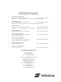
TABLE OF CONTENTS
Section / Title Page
1.0 Safety Precautions . . . . . . . . . . . . . . . . . . . . . . . . . . . . . . . . . . . . . . . . . . . . . . . . . . . . . . . . . . . . . . . . . . . . . . . . . . . . . . . . . . . .5
1.1 Safety - English . . . . . . . . . . . . . . . . . . . . . . . . . . . . . . . . . . . . . . . . . . . . . . . . . . . . . . . . . . . . . . . . . . . . . . . . . . . . . . . . . .5
1.2 Safety - Spanish . . . . . . . . . . . . . . . . . . . . . . . . . . . . . . . . . . . . . . . . . . . . . . . . . . . . . . . . . . . . . . . . . . . . . . . . . . . . . . . . .9
1.3 Safety - French . . . . . . . . . . . . . . . . . . . . . . . . . . . . . . . . . . . . . . . . . . . . . . . . . . . . . . . . . . . . . . . . . . . . . . . . . . . . . . . . .13
2.0 Description . . . . . . . . . . . . . . . . . . . . . . . . . . . . . . . . . . . . . . . . . . . . . . . . . . . . . . . . . . . . . . . . . . . . . . . . . . . . . . . . . . . . . . . . . .19
2.1 Requirements . . . . . . . . . . . . . . . . . . . . . . . . . . . . . . . . . . . . . . . . . . . . . . . . . . . . . . . . . . . . . . . . . . . . . . . . . . . . . . . . . .19
2.2 Options . . . . . . . . . . . . . . . . . . . . . . . . . . . . . . . . . . . . . . . . . . . . . . . . . . . . . . . . . . . . . . . . . . . . . . . . . . . . . . . . . . . . . . . .19
3.0 Installation. . . . . . . . . . . . . . . . . . . . . . . . . . . . . . . . . . . . . . . . . . . . . . . . . . . . . . . . . . . . . . . . . . . . . . . . . . . . . . . . . . . . . . . . . . .21
3.1 AIR CURTAIN KIT Standard / XR Series. . . . . . . . . . . . . . . . . . . . . . . . . . . . . . . . . . . . . . . . . . . . . . . . . . . . . . . . . . . .21
3.2 WATER INJECTION KIT for Air Curtain . . . . . . . . . . . . . . . . . . . . . . . . . . . . . . . . . . . . . . . . . . . . . . . . . . . . . . . . . . . 23
4.0 System Congurations . . . . . . . . . . . . . . . . . . . . . . . . . . . . . . . . . . . . . . . . . . . . . . . . . . . . . . . . . . . . . . . . . . . . . . . . . . . . . . 25
5.0 Parts Lists. . . . . . . . . . . . . . . . . . . . . . . . . . . . . . . . . . . . . . . . . . . . . . . . . . . . . . . . . . . . . . . . . . . . . . . . . . . . . . . . . . . . . . . . . . . .27
6.0 Reference PT-36 Consumable & Wears Part Numbers . . . . . . . . . . . . . . . . . . . . . . . . . . . . . . . . . . . . . . . . . . . . . . . . . 29

4
TABLE OF CONTENTS

5
SECTION 1 SAFETY PRECAUTIONS
1.0 Safety Precautions
1.1 Safety - English
WARNING: These Safety Precautions are
for your protection. They summarize pre-
cautionary information from the references
listed in Additional Safety Information sec-
tion. Before performing any installation or operating
procedures, be sure to read and follow the safety precau-
tions listed below as well as all other manuals, material
safety data sheets, labels, etc. Failure to observe Safety
Precautions can result in injury or death.
PROTECT YOURSELF AND OTHERS --
Some welding, cutting, and gouging
processes are noisy and require ear
protection. The arc, like the sun, emits
ultraviolet (UV) and other radiation
and can injure skin and eyes. Hot metal can cause
burns. Training in the proper use of the processes
and equipment is essential to prevent accidents.
Therefore:
1. Always wear safety glasses with side shields in any
work area, even if welding helmets, face shields, and
goggles are also required.
2. Use a face shield tted with the correct lter and
cover plates to protect your eyes, face, neck, and
ears from sparks and rays of the arc when operating
or observing operations. Warn bystanders not to
watch the arc and not to expose themselves to the
rays of the electric-arc or hot metal.
3. Wear ameproof gauntlet type gloves, heavy long-
sleeve shirt, cuess trousers, high-topped shoes,
and a welding helmet or cap for hair protection, to
protect against arc rays and hot sparks or hot metal.
A ameproof apron may also be desirable as protec-
tion against radiated heat and sparks.
4. Hot sparks or metal can lodge in rolled up sleeves,
trouser cus, or pockets. Sleeves and collars should
be kept buttoned, and open pockets eliminated from
the front of clothing.
5. Protect other personnel from arc rays and hot sparks
with a suitable non-ammable partition or curtains.
6. Use goggles over safety glasses when chipping slag
or grinding. Chipped slag may be hot and can y far.
Bystanders should also wear goggles over safety
glasses.
FIRES AND EXPLOSIONS -- Heat from
ames and arcs can start res. Hot
slag or sparks can also cause res and
explosions. Therefore:
1. Remove all combustible materials well away from
the work area or cover the materials with a protec-
tive non-ammable covering. Combustible materials
include wood, cloth, sawdust, liquid and gas fuels,
solvents, paints and coatings, paper, etc.
2. Hot sparks or hot metal can fall through cracks or
crevices in oors or wall openings and cause a hid-
den smoldering re or res on the oor below. Make
certain that such openings are protected from hot
sparks and metal.“
3. Do not weld, cut or perform other hot work until the
workpiece has been completely cleaned so that there
are no substances on the workpiece which might
produce ammable or toxic vapors. Do not do hot
work on closed containers. They may explode.
4. Have re extinguishing equipment handy for instant
use, such as a garden hose, water pail, sand bucket,
or portable re extinguisher. Be sure you are trained
in its use.
5. Do not use equipment beyond its ratings. For ex-
ample, overloaded welding cable can overheat and
create a re hazard.
6. After completing operations, inspect the work area
to make certain there are no hot sparks or hot metal
which could cause a later re. Use re watchers when
necessary.
7. For additional information, refer to NFPA Standard
51B, "Fire Prevention in Use of Cutting and Welding
Processes", available from the National Fire Protec-
tion Association, Batterymarch Park, Quincy, MA
02269.
ELECTRICAL SHOCK -- Contact with
live electrical parts and ground can
cause severe injury or death. DO NOT
use AC welding current in damp areas,
if movement is conned, or if there is
danger of falling.

6
1. Be sure the power source frame (chassis) is con-
nected to the ground system of the input power.
2. Connect the workpiece to a good electrical ground.
3. Connect the work cable to the workpiece. A poor
or missing connection can expose you or others
to a fatal shock.
4. Use well-maintained equipment. Replace worn or
damaged cables.
5. Keep everything dry, including clothing, work area,
cables, torch/electrode holder, and power source.
6. Make sure that all parts of your body are insulated
from work and from ground.
7. Do not stand directly on metal or the earth while
working in tight quarters or a damp area; stand
on dry boards or an insulating platform and wear
rubber-soled shoes.
8. Put on dry, hole-free gloves before turning on the
power.
9. Turn o the power before removing your gloves.
10. Refer to ANSI/ASC Standard Z49.1 (listed on
next page) for specic grounding recommenda-
tions. Do not mistake the work lead for a ground
cable.
ELECTRIC AND MAGNETIC FIELDS — May be
dangerous. Electric current owing through any
conductor causes localized Electric
and Magnetic Fields (EMF). Welding
and cutting current creates EMF
around welding cables and welding
machines. Therefore:
1. Welders having pacemakers should consult their
physician before welding. EMF may interfere with
some pacemakers.
2. Exposure to EMF may have other health eects which
are unknown.
3. Welders should use the following procedures to
minimize exposure to EMF:
A. Route the electrode and work cables together.
Secure them with tape when possible.
B. Never coil the torch or work cable around your
body.
C. Do not place your body between the torch and
work cables. Route cables on the same side of
your body.
D. Connect the work cable to the workpiece as close
as possible to the area being welded.
E. Keep welding power source and cables as far
away from your body as possible.
FUMES AND GASES -- Fumes and
gases, can cause discomfort or harm,
particularly in conned spaces. Do
not breathe fumes and gases. Shield-
ing gases can cause asphyxiation.
Therefore:
1. Always provide adequate ventilation in the work area
by natural or mechanical means. Do not weld, cut, or
gouge on materials such as galvanized steel, stain-
less steel, copper, zinc, lead, beryllium, or cadmium
unless positive mechanical ventilation is provided.
Do not breathe fumes from these materials.
2. Do not operate near degreasing and spraying opera-
tions. The heat or arc rays can react with chlorinated
hydrocarbon vapors to form phosgene, a highly
toxic gas, and other irritant gases.
3. If you develop momentary eye, nose, or throat ir-
ritation while operating, this is an indication that
ventilation is not adequate. Stop work and take
necessary steps to improve ventilation in the work
area. Do not continue to operate if physical discom-
fort persists.
4. Refer to ANSI/ASC Standard Z49.1 (see listing below)
for specic ventilation recommendations.
SECTION 1 SAFETY PRECAUTIONS

7
5. WARNING: This product, when used for welding
or cutting, produces fumes or gases
which contain chemicals known to
the State of California to cause birth
defects and, in some cases, cancer.
(California Health & Safety Code
§25249.5 et seq.)
CYLINDER HANDLING -- Cylinders,
if mishandled, can rupture and vio-
lently release gas. Sudden rupture
of cylinder, valve, or relief device can
injure or kill. Therefore:
1. Use the proper gas for the process and use the
proper pressure reducing regulator designed to
operate from the compressed gas cylinder. Do not
use adaptors. Maintain hoses and ttings in good
condition. Follow manufacturer's operating instruc-
tions for mounting regulator to a compressed gas
cylinder.
2. Always secure cylinders in an upright position by
chain or strap to suitable hand trucks, undercar-
riages, benches, walls, post, or racks. Never secure
cylinders to work tables or xtures where they may
become part of an electrical circuit.
3. When not in use, keep cylinder valves closed. Have
valve protection cap in place if regulator is not con-
nected. Secure and move cylinders by using suitable
hand trucks. Avoid rough handling of cylinders.
4. Locate cylinders away from heat, sparks, and ames.
Never strike an arc on a cylinder.
5. For additional information, refer to CGA Standard P-1,
"Precautions for Safe Handling of Compressed Gases
in Cylinders", which is available from Compressed
Gas Association, 1235 Jeerson Davis Highway,
Arlington, VA 22202.
EQUIPMENT MAINTENANCE -- Faulty or
improperly maintained equipment can
cause injury or death. Therefore:
1. Always have qualied personnel perform the instal-
lation, troubleshooting, and maintenance work.
Do not perform any electrical work unless you are
qualied to perform such work.
2. Before performing any maintenance work inside a
power source, disconnect the power source from
the incoming electrical power.
3. Maintain cables, grounding wire, connections, power
cord, and power supply in safe working order. Do
not operate any equipment in faulty condition.
4. Do not abuse any equipment or accessories. Keep
equipment away from heat sources such as furnaces,
wet conditions such as water puddles, oil or grease,
corrosive atmospheres and inclement weather.
5. Keep all safety devices and cabinet covers in position
and in good repair.
6. Use equipment only for its intended purpose. Do
not modify it in any manner.
ADDITIONAL SAFETY INFORMATION -- For
more information on safe practices for
electric arc welding and cutting equip-
ment, ask your supplier for a copy of
"Precautions and Safe Practices for Arc
Welding, Cutting and Gouging", Form
52-529.
The following publications, which are available from
the American Welding Society, 550 N.W. LeJuene Road,
Miami, FL 33126, are recommended to you:
1. ANSI/ASC Z49.1 - "Safety in Welding and Cutting"
2. AWS C5.1 - "Recommended Practices for Plasma Arc
Welding"
3. AWS C5.2 - "Recommended Practices for Plasma Arc
Cutting"
4. AWS C5.3 - "Recommended Practices for Air Carbon
Arc Gouging and Cutting"
SECTION 1 SAFETY PRECAUTIONS

8
SECTION 1 SAFETY PRECAUTIONS
5. AWS C5.5 - "Recommended Practices for Gas Tung-
sten Arc Welding“
6. AWS C5.6 - "Recommended Practices for Gas Metal
Arc Welding"“
7. AWS SP - "Safe Practices" - Reprint, Welding Hand-
book.
8. ANSI/AWS F4.1, "Recommended Safe Practices for
Welding and Cutting of Containers That Have Held
Hazardous Substances."
MEANING OF SYMBOLS - As used
throughout this manual: Means Atten-
tion! Be Alert! Your safety is involved.
Means immediate hazards which,
if not avoided, will result in im-
mediate, serious personal injury
or loss of life.
Means potential hazards which
could result in personal injury or
loss of life.
Means hazards which could result
in minor personal injury.
Page is loading ...
Page is loading ...
Page is loading ...
Page is loading ...
Page is loading ...
Page is loading ...
Page is loading ...
Page is loading ...

17
A hazard exists whenever a water table is used with plasma arc cutting. Severe explosions have resulted from the ac-
cumulation of hydrogen beneath the plate being cut. Thousands of dollars in property damage have been caused by
these explosions. Personal injury or death could result from such an explosion.
The best available information indicates that three possible sources of hydrogen exists in water tables:
1. Molten Metal Reaction
Most of the hydrogen is liberated by a fast reaction of molten metal from the kerf in the water to form metallic ox-
ides. This reaction explains why reactive metals with greater anity for oxygen, such as aluminum and magnesium,
release greater volumes of hydrogen during the cut than does iron or steel. Most of this hydrogen will come to the
surface immediately, but some will cling to small metallic particles. These particles will settle to the bottom of the
water table and the hydrogen will gradually bubble to the surface.
2. Slow Chemical Reaction
Hydrogen may also result from the slower chemical reactions of cold metal particles with the water, dissimilar metals,
or chemicals in the water. The hydrogen gradually bubbles to the surface.
3. Plasma Shield Gas
Hydrogen or other fuel gases, such as Methane (CH
4
), may come from the plasma or shield gas. H-35 is a commonly
used plasma gas. This gas is 35% hydrogen by volume. When using H-35 at high currents, as much as 125 cfh of
hydrogen will be released.
Regardless of the source, the hydrogen gas can collect in pockets formed by the plate being cut and slats on the
table, or pockets from warped plate. There can also be accumulation of hydrogen under the slag tray or even in the
air reservoir, if these are part of the table design. The hydrogen, in the presence of oxygen or air, can then be ignited
by the plasma arc or a spark from any source.
4. Follow these practices to reduce hydrogen generation and accumulation:
A. Clean the slag (especially ne particles) from the bottom of the table frequently. Rell the table with clean water.
B. Do not leave plates on the table overnight or a weekend.
C. If a water table has been unused for several hours, vibrate it in some way before the rst plate is laid in position.
This will allow accumulated hydrogen in the refuse to break loose and dissipate before it is conned by a plate
on the table. This might be accomplished by laying the rst plate onto the table with a slight jolt, then raising
the plate to permit hydrogen to escape before it is nally set down for cutting.
D. If cutting above water, install fans to circulate air between the plate and the water surface.
E. If cutting underwater, agitate the water under the plate to prevent accumulation of hydrogen. This can be done
by aerating the water using compressed air.
F. If possible, change the level of the water between cuts to dissipate accumulated hydrogen.
G. Maintain pH level of the water near 7 (neutral). This reduces the rate of chemical reaction between water and
metals.
DANGER
SECTION 1 SAFETY PRECAUTIONS
Hydrogen explosion hazard! Read the following before attempting
to cut when using a water table.

18
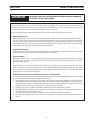
Spark hazard.
Heat, spatter, and sparks cause re and burns.
• Do not cut near combustible material.
• Do not cut containers that have held combustibles.
• Do not have on your person any combustibles (e.g. butane lighter).
• Pilot arc can cause burns. Keep torch nozzle away from yourself and oth-
ers when activating plasma process.
• Wear correct eye and body protection.
• Wear gauntlet gloves, safety shoes and hat.
• Wear ame-retardant clothing that covers all exposed areas.
• Wear cuess trousers to prevent entry of sparks and slag.
WARNING
Aluminum-Lithium (Al-Li) alloys are used in the aerospace industry because of 10% weight
savings over conventional aluminum alloys. It has been reported that molten Al-Li alloys
can cause explosions when they come into contact with water. Therefore, plasma cutting
of these alloys should not be attempted in the presence of water. These alloys should only
be dry cut on a dry table. Alcoa has determined that "dry" cutting on a dry table is safe
and gives good cutting results. DO NOT dry cut over water. DO NOT water injection cut.
The following are some of the Al-Li alloys currently available:
Alithlite (Alcoa) X8192 (Alcoa)
Alithally (Alcoa) Navalite (U. S. Navy)
2090 Alloy (Alcoa) Lockalite (Lockhead)
X8090A (Alcoa) Kalite (Kaiser)
X8092 (Alcoa) 8091 (Alcan)
For additional details and information on the safe use from the hazards associated with
these alloys, contact your aluminum supplier.
Oil And Grease Can Burn Violently!
• Never use oil or grease on this torch.
• Handle torch clean hands only on clean surface.
• Use silicone lubricant only where directed.
• Oil and grease are easily ignited and burn violently in the presence of oxy-
gen under pressure.
WARNING
WARNING
SECTION 1 SAFETY PRECAUTIONS
Possible explosion hazard from plasma cutting aluminum-lithium alloys!

19
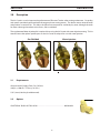
The Air Curtain is used to improve the performance of Plasmarc Torches when cutting underwater. Cut quality
and speed is particularly enhanced with the oxygen plasma cutting process. The device mounts onto the torch
and produces a curtain of air. This allows the plasma arc to operate in a relatively dry zone, although the torch
has been submerged to reduce noise, fumes, and arc radiation.
The supplemental Water Injection Kit is required when using the Air Curtain with water injection cutting. This kit
contains items that replace specic parts on the Air Curtain to adapt it for use with water injection.
SECTION 2 DESCRIPTION
Compressed Air Supply (Clean, Dry, Oil-free).
( 80 psi @ 1200 cfh / 5.5 bar @ 34 m
3
/h )
5/32” (4 mm) Hex Key (Installation tool)
2.0 Description
2.1 Requirements
2.2 Options
DATE
RELEASED FOR
ENGLISH DWG
TITLE
REPRO MADE FROM
SIMILAR TO
SUP.
SUP. BY
APPROVED
BY
DATE
CHECKED
BY
DATE
DRAWN
BY
DATE
SCALE
FIRST MADE FOR
ESAB WELDING & CUTTING PRODUCTS
FLORENCE, SC 29501
UNLESS OTHERWISE
SPECIFIED, DIM ARE
IN INCHES.
TOL .XX
.XXX
ANGLES
CHAMFERS & C'SINKS 2
SURFACE ROUGHNESS IS IN
REMOVE ALL BURRS
BREAK SHARP EDGES
MICROINCHES
M
CHANGE
BY
DATE
CH'KD
THIS DRAWING CONTAINS PROPRIETARY CONFIDENTIAL INFORMATION OF ESAB WELDING &
CUTTING PRODUCTS AND IS LOANED WITH THE EXPRESS AGREEMENT THAT THIS DRAWING
(1) WILL NOT BE REPRODUCED OR COPIED, (2) WILL NOT BE USED OTHER THAN IN WORK
FOR ESAB WELDING & CUTTING PRODUCTS, AND (3) WILL NOT BE DISCLOSED EXCEPT
TO EMPLOYEES OF THE PARTY TO WHOM THIS DRAWING IS LOANED ON A CONFIDENTIAL BASIS.
A-
A-
MATERIAL:
.015
.005
PRO/ENGINEER DWG.
NOV.1994
A
A
19X19
ADAPT B-A/W*F B-A/W*M 90ASSY
19X19
BLP
10/23/08
63
2
1:1
FINISH:
BRIGHT DIP PER SPI 45.315.3 METHOD 6
P/N QTY DESCRIPTION
1. 836Z40 1 NUT HOSE B/A-W* .63-18F RH OLD
2. 03Z59 1 NPL B/SIZE .425ODX 0.81LG
3. 19Z48 1 BODY FOR 90 AIR WATER ADAPTOR
4. 6270869 1 RING SSBAG-1 0.438KDX.03D STD
"E" CN-083187 REVISED & RED BLP
WSS10/23/08
WSS
10/23/08
WSS
10/23/08
1
2
3
4
ADAPTOR 90° RH B/A-W*F B/A-W*M .........................................................................0560948613
Standard XR Series < 250A > 250A
Gas Shielded Water Injection

20
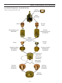
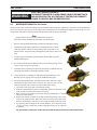
PARTS CONFIGURATION OVERVIEW
Gas Shielded Conguration - Standard & XR Series
*Nozzle
*Nozzle Retaining Cup
0004470045
*Diuser
*Shield
Bushing
0004485802
*XR Series
Nozzle
*XR Series
Nozzle Retaining Cup
0558009550
*XR Series
Shield
STD/XR Sleeve
0558009391
Wave Spring
0558009390
Standard
Sleeve Cap
0558009394
XR Series Insulated
Shield Retainer
0558009392
Retainer
0004470104
O-ring 2.625 ID
0004470101
Body
0004470099
Standard Insulated
Shield Retainer
0558009395
XR Series
Sleeve Cap
0558009393
* Reference Only (Not Included in Kit)

21
ELECTRIC SHOCK CAN KILL!
DISCONNECT POWER TO PLASMA POWER SOURCE BEFORE TOUCH-
ING OR SERVICING THE AIR CURTAIN AT THE TORCH.DISCONNECT
POWER TO CONTROL BOX BEFORE SERVICING.
WARNING
3.0 Installation
SECTION 3 INSTALLATION
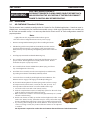
3.1 AIR CURTAIN KIT Standard / XR Series
1. Remove existing Nozzle Retaining Cup before installing Air Curtain.
2. Slide Bushing and chrome plated Air Curtain Body onto the stainless
steel body of the PT-36 torch. Snug locking collar screw with a 5/32”
(4mm) hex key. Final positioning and tightening will be done at the last
step.
3. Install appropriate Nozzle and Nozzle Retaining Cup.
4. Pre-assemble appropriate Diuser, Shield, and Shield Retainer to ensure
proper contact. Hand-tighten this assembly onto the torch. Double
check that the parts are properly seated.
5. Pre-assemble the Air Curtain Std/XR Sleeve, Wave Spring, and Sleeve
Cap. Hand-tighten the Sleeve Cap.
6. Install this Sleeve assembly over the now completely assembled torch,
by pushing it into the Air Curtain Body until fully seated.
7. Secure the Sleeve assembly by installing the Air Curtain Retainer. The
Retainer turns to engage or disengage on the Body locking pins.
8. Air Curtain Positioning Detail: The Wave Spring works well over a range
of compression from under .050” (1.2 mm) to over .200” (5.1 mm). The
desired position of the Air Curtain is near the middle of this range.
Note:
Lightly lubricate all o-rings with included silicone grease.
Also refer to Parts Conguration Overview on previous page.
The kit contains items needed to congure the Air Curtain for Gas Shielded applications. Note that some in-
cluded items are needed only for Standard consumable set-ups, while some included items are needed only
for XR Series consumable set-ups. It is necessary that the Air Curtain and PT-36 Torch congurations match for
proper operation.
a. Loosen the collar screw with a 5/32” (4mm) hex key.
b. Push the completed Air Curtain assembly fully upward on the torch body
until you detect resistance from the wave spring.
c. Make a mark on the stainless steel torch body approximately 1/8” (3.2mm)
above the collar bushing.
d. Push the Air Curtain assembly up to that mark and tighten the collar screw
with a 5/32” (4mm) hex key. (Note that it may be easier perform this step if
the Air Curtain Retainer and Sleeve / Sleeve Cap assembly are rst removed).
e. Try removing and installing the Air Curtain Retainer. If the bayonet action
seems too strong or weak, the position of the Air Curtain can be adjusted
as needed.
No adjustment is required to set the clearance between the torch front end and the Air Curtain.

22
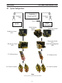
*Water Injection Nozzle
(greater than 250 amps)
Sleeve Insert 16mm
(250 amps or less)
0558009387
Bushing
0004485802
*Water Injection Nozzle
(250 amps or less)
*Water Injection
Nozzle Retaining Cup
0558009300
Sleeve
0558009389
Wave Spring
0558009390
Retainer
0004470104
O-ring 2.625 ID
0004470101
Body
0004470099
Sleeve Insert 14mm
(greater than 250 amps)
0558009386
SECTION 3 INSTALLATION
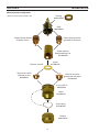
Water Injection Conguration
* Reference Only (Not Included in Kit)
Spacer
0558009388
(Grooves upward)

23
3.2 WATER INJECTION KIT for Air Curtain
SECTION 3 INSTALLATION
The kit contains items needed to congure the Air Curtain for Water Injection applications. Note that some included items
are needed only for lower current set-ups, while some included items are needed only for higher current set-ups. It is nec-
essary that the Air Curtain and PT-36 Torch congurations match for proper operation.
1. Remove existing Nozzle Retaining Cup before installing Air Curtain.
2. Slide Bushing and chrome plated Air Curtain Body onto the stainless
steel body of the PT-36 torch. Snug locking collar screw with a 5/32”
(4mm) hex key. Final positioning and tightening will be done at the last
step.
3. Install an appropriate Water Injection Nozzle and the Water Injection
Nozzle Retaining Cup.
4. Pre-assemble the Air Curtain Water Injection Sleeve, Wave Spring, Sleeve
Insert, and Spacer (grooves upward).
5. Install this Sleeve assembly over the now completely assembled torch, by
pushing it into the Air Curtain Body until fully seated.
6. Secure the Sleeve assembly by installing the Air Curtain Retainer. The
Retainer turns to engage or disengage on the Body locking pins.
7. Air Curtain Positioning Detail: The Wave Spring works well over a range
of compression from under .050” (1.2 mm) to over .200” (5.1 mm). The de-
sired position of the Air Curtain is near the middle of this range.
Note:
Lightly lubricate all o-rings with included silicone grease.
Also refer to Parts Conguration Overview on previous page.
a. Loosen the collar screw with a 5/32” (4mm) hex key.
b. Push the completed Air Curtain assembly fully upward on the torch body
until you detect resistance from the wave spring.
c. Make a mark on the stainless steel torch body approximately 1/8” (3.2mm)
above the collar bushing.
d. Push the Air Curtain assembly up to that mark and tighten the collar screw
with a 5/32” (4mm) hex key. (Note that it may be easier perform this step if
the Air Curtain Retainer and Sleeve / Sleeve Cap assembly are rst removed).
e. Try removing and installing the Air Curtain Retainer. If the bayonet action
seems too strong or weak, the position of the Air Curtain can be adjusted
as needed.
ELECTRIC SHOCK CAN KILL!
DISCONNECT POWER TO PLASMA POWER SOURCE BEFORE TOUCH-
ING OR SERVICING THE AIR CURTAIN AT THE TORCH.DISCONNECT
POWER TO CONTROL BOX BEFORE SERVICING.
WARNING
No adjustment is required to set the clearance between the torch front end and the Air Curtain.

24
SECTION 3 INSTALLATION

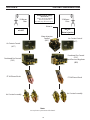
25
25 Micron
Filter
Note:
See m3 plasma system manual for details.
Compressed Air Supply
(Air Curtain)
Source: 80 psi @ 1200cfh
(5.5 bar @ 34 m
3
/h)
Use clean, dry, oil free shop air
SECTION 4 SYSTEM CONFIGURATIONS
PT-36 Plasma Torch
Air Curtain Assembly
25 Micron
Filter
Shield Gas Control
(SGC)
Plasma Gas Control
(PGC)
PT-36 Plasma Torch
Air Curtain Assembly
Shield Gas Control
(SGC)
Plasma Gas Control
(PGC)
4.0 System Congurations
Back Pressure Regulator
(BPR)
Water Injection
Control
(WIC)
Water In
m3-G2
+
Water Injection
m3-G2

26
25 Micron
Filter
Compressed Air Supply
(Air Curtain)
Source: 80 psi @ 1200cfh
(5.5 bar @ 34 m
3
/h)
Use clean, dry, oil free shop air
25 Micron
Filter
Air Curtain Control
(ACC)
Air Curtain Control
(ACC)
Combined Gas Control
(CGC)
Combined Gas Control
(CGC)
PT-36 Plasma Torch
Air Curtain Assembly
PT-36 Plasma Torch
Air Curtain Assembly
m3-IGC
+
Water Injection
m3-IGC
SECTION 4 SYSTEM CONFIGURATIONS
Note:
See m3 plasma system manual for details.
Back Pressure Regulator
(BPR)
Water Injection
Control
(WIC)
Water In

27
SECTION 5 PARTS LISTS
5.0 Parts Lists
PT-36 Air Curtain Std / XR Kit - 0558009774
Qty Part No Description
1 0004470099 BODY AIR CURTAIN PT-36
1 0004485802 BUSHING AIR CURTAIN PT-36
1 0004470104 RETAINER AIR CURTAIN PT-36
1 0558009391 SLEEVE AIR CURTAIN STD / XR PT-36
1 0558009394 CAP SLEEVE STD AIR CURTAIN
1 0558009393 CAP SLEEVE XR AIR CURTAIN
1 0558009395 SHIELD RETAINER STD INS PT-36 A/C
1 0558009392 SHIELD RETAINER XR INS PT-36 A/C
2 0558009390 SPRING WAVE 2.65ID X .128W SST
6 0004470101 O-RING 2.625 ID x .094 NBR
1 0004470869 GREASE SILICONE DOW DC-111 (5.3 Oz)
PT-36 Air Curtain Water Injection Kit - 0558009385
Qty Part No Description
1 0558009389 SLEEVE AIR CURT WTR INJ PT-36
5 0558009386 INSERT SLEEVE A/C WTR INJ 14MM (.56)
5 0558009387 INSERT SLEEVE A/C WTR INJ 16MM (.63)
5 0558009388 SPACER AIR CURTAIN WTR INJ
1 0558009390 SPRING WAVE 2.65ID X .128W SST
5 0004470101 O-RING 2.625 ID x .094 NBR
Optional 90 Degree Air Curtain Fitting
Part No Description
0560948613 ADAPTOR 90° RH B/A-W*F B/A-W*M

28
SECTION 5 PARTS LISTS
Page is loading ...
Page is loading ...
Page is loading ...
Page is loading ...
-
 1
1
-
 2
2
-
 3
3
-
 4
4
-
 5
5
-
 6
6
-
 7
7
-
 8
8
-
 9
9
-
 10
10
-
 11
11
-
 12
12
-
 13
13
-
 14
14
-
 15
15
-
 16
16
-
 17
17
-
 18
18
-
 19
19
-
 20
20
-
 21
21
-
 22
22
-
 23
23
-
 24
24
-
 25
25
-
 26
26
-
 27
27
-
 28
28
-
 29
29
-
 30
30
-
 31
31
-
 32
32


ESAB PLASMARC™ Standard / XR Series Air Curtain Kit User manual
- Category
- Welding System
- Type
- User manual
Ask a question and I''ll find the answer in the document
Finding information in a document is now easier with AI

