
Specifications, descriptions and illustrative material in this literature are as accurate as known at the time
of publication, but are subject to change without notice. Illustrations may include optional equipment and
accessories, and may not include all standard equipment.
Operator’s Manual
X7722273204
© 04/2013 ECHO Inc.
x7722271404 / x772000164
GT-225
Grass Trimmer
Burn Hazard
The muffler or catalytic muffler and surrounding cover may become extremely hot.
Always keep clear of exhaust and muffler area, otherwise serious personal injury may
occur.
The engine exhaust from this product contains chemicals known to the State of California to cause
cancer, birth defects or other reproductive harm.
Users of this equipment risk injury to themselves and others if the unit is used
improperly and/or safety precautions are not followed. ECHO provides an operator’s
manual and a safety manual. Both must be read and understood for proper and safe
operation. Failure to do so could result in serious injury.

2 X7722273204
© 04/2013 ECHO Inc.
TABLE OF CONTENTS GT-225
TABLE OF CONTENTS
Table of Contents .............................................................................................................................. 2
Introduction ........................................................................................................................................ 3
The Operator’s Manual ................................................................................................................ 3
The Safety Manual....................................................................................................................... 3
Servicing Information ......................................................................................................................... 3
Parts/Serial Number..................................................................................................................... 3
Service......................................................................................................................................... 3
Echo Consumer Product Support ................................................................................................ 3
Warranty Registration .................................................................................................................. 3
Additional or Replacement Manuals ............................................................................................ 4
Safety................................................................................................................................................. 4
Manual Safety Symbols and Important Information ..................................................................... 4
International Symbols .................................................................................................................. 5
Personal Condition and Safety Equipment .................................................................................. 5
Equipment.................................................................................................................................... 8
Emission Control (Exhaust & Evaporative)........................................................................................ 8
EPA 2010 and Later and/or C.A.R.B. TIER III ............................................................................. 8
Description....................................................................................................................................... 10
Contents .......................................................................................................................................... 12
Assembly ......................................................................................................................................... 13
Plastic Shield Installaion ............................................................................................................ 13
Nylon Line Head Installation ...................................................................................................... 13
Nylon Line Installation................................................................................................................ 14
Front (Loop) Handle................................................................................................................... 14
Operation ......................................................................................................................................... 15
Fuel............................................................................................................................................ 15
Starting Cold Engine.................................................................................................................. 16
Starting Warm Engine................................................................................................................ 18
Stopping Engine......................................................................................................................... 18
Maintenance .................................................................................................................................... 19
Skill Levels................................................................................................................................. 19
Maintenance Intervals................................................................................................................ 19
Air Filter...................................................................................................................................... 20
Fuel Filter................................................................................................................................... 20
Spark Plug ................................................................................................................................. 21
Cooling System.......................................................................................................................... 21
Exhaust System......................................................................................................................... 22
Carburetor Adjustment............................................................................................................... 23
Lubrication ................................................................................................................................. 24
Troubleshooting ............................................................................................................................... 25
Storage ............................................................................................................................................ 26
Long Term Storage (Over 30 Days)........................................................................................... 26
Specifications................................................................................................................................... 27
Warranty Statements ....................................................................................................................... 28
Notes ............................................................................................................................................... 30

GT-225 INTRODUCTION
X7722273204 3
© 04/2013 ECHO Inc.
INTRODUCTION
Welcome to the ECHO family. This ECHO product was designed and manufactured to provide long life and
on-the-job dependability. Read and understand this manual and the SAFETY MANUAL. You will find both
easy to use and full of helpful operating tips and SAFETY messages.
The Operator’s Manual
Keep it in a safe place for future reference. Contains specifications and information for safety, operation,
maintenance, storage and assembly specific to this product.
The Safety Manual
Keep it in a safe place for future reference. Explains possible hazards and the measures you should take to
insure safe operation.
SERVICING INFORMATION
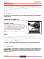
Parts/Serial Number
Genuine ECHO Parts and ECHO REPOWER™ Parts and
Assemblies for your ECHO products are available only from an
Authorized ECHO Dealer. When you do need to buy parts always
have the Model Number and Serial Number of the unit with you. You
can find these numbers on the engine housing. For future
reference, write them in the space provided below.
Model No. _________________ SN. ___________________
Service
Service of this product during the warranty period must be performed by an Authorized ECHO Service
Dealer. For the name and address of the Authorized ECHO Service Dealer nearest you, ask your retailer or
call: 1-800-432-ECHO (3246). Dealer information is also available on our Web Site. When presenting your
unit for Warranty service/repairs, proof of purchase is required.
Echo Consumer Product Support
If you require assistance or have questions concerning the application, operation or maintenance of this
product you may call the ECHO Consumer Product Support Department at 1-800-673-1558 from 8:30 am to
4:30 pm (Central Standard Time) Monday through Friday. Before calling, please know the model and serial
number of your unit.
Warranty Registration
To ensure trouble free warranty coverage it is important that you register your ECHO equipment on-line at
www.echo-usa.com
or by filling out the warranty registration card supplied with your unit. Registering your
product confirms your warranty coverage and provides a direct link between you and ECHO if we find it
necessary to contact you.

4 X7722273204
© 04/2013 ECHO Inc.
SAFETY GT-225
Additional or Replacement Manuals
Replacement Operator, Safety Manuals, and Parts Catalogs are available from your ECHO dealer or at
www.echo-usa.com or by contacting ECHO Inc., 400 Oakwood Road, Lake Zurich, IL 60047
(800-673-1558). Always check the ECHO Web Site for updated information.
Safety Videos are available from your Echo dealer. A $5.00 shipping charge will be required for each video.
SAFETY
Manual Safety Symbols and Important Information
Throughout this manual and on the product itself, you will find safety alerts and helpful, informational
messages preceded by symbols or key words. The following is an explanation of those symbols and key
words and what they mean to you.
The safety alert symbol accompanied by the word “DANGER” calls attention to an act or condition
which WILL lead to serious personal injury or death if not avoided.
The safety alert symbol accompanied by the word “WARNING” calls attention to an act or condition
which CAN lead to serious personal injury or death if not avoided.
The safety alert symbol accompanied by the word “CAUTION” calls attention to an act or condition
which may lead to minor or moderate personal injury if not avoided.
The enclosed message provides information necessary for the protection of the unit.
Note: This enclosed message provides tips for use, care and maintenance of the unit.
CIRCLE AND SLASH SYMBOL
This symbol means the specific action shown is prohibited. Ignoring these prohibitions can result
in serious or fatal injury.

GT-225 SAFETY
X7722273204 5
© 04/2013 ECHO Inc.
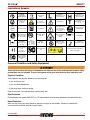
International Symbols
Personal Condition and Safety Equipment
Users of this product risk injury to themselves and others if the unit is used improperly and/or safety
precautions are not followed. Proper clothing and safety gear must be worn when operating unit.
Physical Condition
Your judgment and physical dexterity may not be good:
• if you are tired or sick,
• if you are taking medication,
• if you have taken alcohol or drugs.
Operate unit only if you are physically and mentally well.
Eye Protection
Eye protection that meets ANSI Z87.1 or CE requirements must be worn whenever you operate the unit.
Hand Protection
Wear no-slip, heavy duty work gloves to improve your grip on the handles. Gloves also reduce the
transmission of machine vibration to your hands.
Symbol Description Symbol Description Symbol Description Symbol Description
Read and
understand
owners manual.
Fuel and oil
mixture
Carburetor
Adjustment - Low
speed mixture
Carburetor
Adjustment - High
speed mixture
Wear eye, ear
and head
protection
Rotating
Cutting Attachment
Safety/Alert
Carburetor
Adjustment - Idle
speed
Emergency Stop Hot Surface
Avoid all power
lines. This unit is
not insulated
against electrical
current.
Do not exceed
10,000 RPM.
Wear hand and
foot protection.
Use two handed
DO NOT smoke
near fuel
Plan retreat path
from falling
objects
Primer Bulb
Choke Control
“Cold Start”
Position (Choke
Closed)
Ignition
ON / OFF
DO NOT allow
flames or sparks
near fuel
Wear slip
resistant footwear
Choke Control
"Run"
Position
(Choke Open)
Do not use
blades. String line
only.
Keep bystanders and helpers
away 15 m (50 ft.).
Do not operate
without guards
and shields in
place.

6 X7722273204
© 04/2013 ECHO Inc.
SAFETY GT-225
Breathing Protection
Wear a facemask to protect against dust.
Hearing Protection
ECHO recommends wearing hearing protection whenever unit is used.
Proper Clothing
Wear snug fitting, durable clothing;
• Pants should have long legs, shirts with long sleeves.
• DO NOT WEAR SHORTS,
• DO NOT WEAR TIES, SCARVES, JEWELRY, or clothing with loose or hanging items that could become
entangled in moving parts or surrounding growth.
Wear sturdy work shoes with nonskid soles;
• DO NOT WEAR OPEN TOED SHOES,
• DO NOT OPERATE UNIT BAREFOOTED.
Wear no-slip, heavy duty work gloves.
Keep long hair away from engine and air intake. Retain hair with cap or net.
Hot Humid Weather
Heavy protective clothing can increase operator fatigue which may lead to heat stroke. Schedule heavy work
for early morning or late afternoon hours when temperatures are cooler.
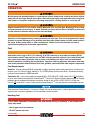
The ignition componentsof this machine generate an electromagnetic fieldduring operation which
may interfere with some pacemakers.To reduce the risk of serious or fatal injury, persons with
pacemakers should consult with their physician and the pacemaker manufacturer before operating
this machine.In the absence of such information, ECHO does not recommend the use ofECHO
products by anyonewho has a pacemaker.
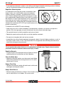
Vibration and Cold
It is believed that a condition called Raynaud’s Phenomenon,
which affects the fingers of certain individuals, may be brought
about by exposure to vibration and cold. Exposure to vibration
and cold may cause tingling and burning sensations, followed
by loss of color and numbness in the fingers. The following
precautions are strongly recommended, because the minimum
exposure, which might trigger the ailment, is unknown.
• Keep your body warm, especially the head, neck, feet, ankles,
hands, and wrists.
• Maintain good blood circulation by performing vigorous arm exercises during frequent work breaks, and
also by not smoking.
• Limit the hours of operation. Try to fill each day with jobs where operating the unit or other hand-held
power equipment is not required.

GT-225 SAFETY
X7722273204 7
© 04/2013 ECHO Inc.
• If you experience discomfort, redness, and swelling of the fingers followed by whitening and loss of feeling,
consult your physician before further exposing yourself to cold and vibration.
Repetitive Stress Injuries
It is believed that overusing the muscles and tendons of the
fingers, hands, arms, and shoulders may cause soreness,
swelling, numbness, weakness, and extreme pain in those
areas. Certain repetitive hand activities may put you at a high
risk for developing a Repetitive Stress Injury (RSI). An extreme
RSI condition is Carpal Tunnel Syndrome (CTS), which could
occur when your wrist swells and squeezes a vital nerve that
runs through the area. Some believe that prolonged exposure to
vibration may contribute to CTS. CTS can cause severe pain for
months or even years.
To reduce the risk of RSI/CTS, do the following:
• Avoid using your wrist in a bent, extended, or twisted position. Instead try to maintain a straight wrist
position. Also, when grasping, use your whole hand, not just the thumb and index finger.
• Take periodic breaks to minimize repetition and rest your hands.
• Reduce the speed and force with which you do the repetitive movement.
• Do exercise to strengthen the hand and arm muscles.
• Immediately stop using all power equipment and consult a doctor if you feel tingling, numbness, or pain in
the fingers, hands, wrists, or arms. The sooner RSI/CTS is diagnosed, the more likely permanent nerve
and muscle damage can be prevented.
Do not operate this product indoors or in inadequately ventilated areas. Engine exhaust contains
poisonous emissions and can cause serious injury or death.
Read the Manuals
• Provide all users of this equipment with the Operator’s Manual
and Safety Manual for instructions on Safe Operation.
Clear the Work Area
• Spectators and fellow workers must be warned, and children
and animals prevented from coming nearer than 15 m (50 ft.)
while the unit is in use.
Keep a Firm Grip
• Hold the front and rear handles with both hands, with thumbs
and fingers encircling the handles.
Keep a Solid Stance
• Maintain footing and balance at all times. Do not stand on slippery, uneven or unstable surfaces. Do not
work in odd positions or on ladders. Do not over reach.

8 X7722273204
© 04/2013 ECHO Inc.
EMISSION CONTROL (EXHAUST & EVAPORATIVE) GT-225
Avoid Hot Surfaces
• Keep exhaust area clear of flammable debris. Avoid contact
during and immediately after operation.
Equipment
Use only ECHO approved attachments. Serious injury may result from the use of a non-approved
attachment combination. ECHO, INC. will not be responsible for the failure of cutting devices,
attachments or accessories which have not been tested and approved by ECHO. Read and comply
with all safety instructions listed in this manual and safety manual.
• Check unit for loose/missing nuts, bolts, and screws. Tighten and/or replace as needed.
• Inspect shield for damage and ensure that the cut-off knife is securely in place. Replace if either is
damaged or missing.
• Check that the cutting attachment is firmly attached and in safe operating condition.
• Check that handle and harness (if included) are adjusted for safe, comfortable operation. See Assembly
Section for proper adjustment.
Moving parts can amputate fingers or cause severe injuries. Keep hands, clothing and loose objects
away from all openings.
◆ ALWAYS stop engine, disconnect spark plug, and make sure all moving parts have come to a complete
stop before removing obstructions, clearing debris, or servicing unit.
◆ DO NOT start or operate unit unless all guards and protective covers are properly assembled to unit.
◆ NEVER reach into any opening while the engine is running. Moving parts may not be visible through
openings.
Check fuel system for leaks due to fuel tank damage, especially if the unit is dropped. If damage or
leaks are found, do not use unit, otherwise serious personal injury or property damage may occur.
Have unit repaired by an authorized servicing dealer before using.
EMISSION CONTROL (EXHAUST & EVAPORATIVE)
EPA 2010 and Later and/or C.A.R.B. TIER III
The emission control system for the engine is EM (engine modification)
and, if the second to last character of the Engine Family on the Emission
Control Information label (sample below) is “C”, “K”, or “T”, the emission
control system is EM and TWC (3-way catalyst). The fuel tank/fuel line
emission control system is EVAP (evaporative emissions). Evaporative
emissions for California models are only applicable to fuel tanks.

GT-225 EMISSION CONTROL (EXHAUST & EVAPORATIVE)
X7722273204 9
© 04/2013 ECHO Inc.
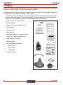
An Emission Control Label is located on the engine. (This is an
EXAMPLE ONLY, information on label varies by engine FAMILY).
Product Emission Durability (Emission Compliance Period)
The 50 or 300 hour emission compliance period is the time span
selected by the manufacturer certifying the engine emissions output
meets applicable emissions regulations, provided that approved
maintenance procedures are followed as listed in the Maintenance Section of this manual.

10 X7722273204
© 04/2013 ECHO Inc.
DESCRIPTION GT-225
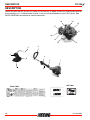
DESCRIPTION
Locate the safety decal(s) on your unit. Make sure the decal(s) is legible and that you understand and follow
the instructions on it. If a decal cannot be read, a new one can be ordered from your ECHO dealer. See
PARTS ORDERING instructions for specific information.
1
2
3
4
5
6
7
8
9
18
10
13
11
12
14
15
17
16
Hot Label
Shaft Label

GT-225 DESCRIPTION
X7722273204 11
© 04/2013 ECHO Inc.
1. POWER HEAD - Factory Assembled to the Driveshaft assembly. Includes the Engine, Clutch, Fuel
System, Ignition System and Recoil Starter.
2. GRIP - Rear (right hand) handle.
3. STOP SWITCH - “SLIDE SWITCH” mounted on top of the Throttle Trigger Housing. Move switch
FORWARD to RUN, BACK to STOP.
4. FRONT HANDLE - The Front (loop) handle is factory assembled to the Drive Shaft assembly but must
be re-positioned for proper cutting attitude and operator comfort.
5. DRIVE SHAFT ASSEMBLY - Factory Assembled to the Power Head. Includes the Rear (right hand)
Handle Assembly, Bearing Housing Assembly, Throttle Trigger, Front (loop, left hand) Handle Assembly,
Flexible Drive Cable and Safety Decals.
6. RAPID LOADER
TM
HEAD - Contains replaceable nylon trimming lines.
7. PLASTIC DEBRIS SHIELD ASSEMBLY - Included in plastic bag (co-pack). MUST be installed on unit
before use, see Assembly Instructions. Shield assembly includes the Cut-Off Knife. Mounts on the Gear
Housing Assembly just above the cutting attachment. Helps protect the operator by deflecting debris
produced during the trimming operation.
8. CUT-OFF KNIFE - Trims line to the correct length.
9. THROTTLE TRIGGER - Controls engine speed. Spring loaded to return to idle when released. During
acceleration, press trigger gradually for best operating technique.
10. TOP GUARD - Provides arm rest during operation and protects arm from hot engine.
11. SPARK ARRESTOR MUFFLER OR SPARK ARRESTOR MUFFLER WITH CATALYST - The muffler or
catalytic muffler controls exhaust noise and emission. The spark arrestor screen prevents hot, glowing
particles of carbon from leaving the muffler. Keep exhaust area clear of flammable debris.
12. FUEL TANK - Contains fuel and fuel filter..
13. RECOIL STARTER/HANDLE - Pull recoil starter handle/rope using light pulling force, approximately
2/3 (2 ft.) of rope length. Two (2) to Six (6) pulls are required to properly tension starter spring prior to
automatic engine engagement. DO NOT let handle snap back or damage to unit will occur.
14. FUEL TANK CAP - Covers and seals fuel tank opening.
15. PURGE BULB - Pumping purge bulb before starting engine draws fresh fuel from the fuel tank, purging
air from the carburetor. Pump purge bulb until fuel is visible and flows freely in the clear fuel tank return
line. Pump purge bulb an additional 4 or 5 times.
16. CHOKE - The choke control is located at the rear of the air cleaner housing. Move choke lever to Cold
Start ( ) to close choke for cold start. Move choke lever to “Run” ( ) position to open choke.
17. AIR CLEANER - Contains replaceable filter element.
18. SPARK PLUG - Provides spark to ignite fuel mixture.

12 X7722273204
© 04/2013 ECHO Inc.
CONTENTS GT-225
CONTENTS
The ECHO product you purchased has been factory pre-assembled for your convenience. Due to packaging
restrictions, shield installation and other assembly may be necessary.
After opening the carton, check for damage. Immediately notify your retailer or ECHO Dealer of damaged or
missing parts. Use the contents list to check for missing parts.
*Some Echo units may be factory pre-assembled. The nylon line head, plastic debris shield, and mounting
hardware shown in the contents list are pre-assembled to the unit. Assembly tools are not supplied with
these units. The front handle may need to be re-positioned for comfortable operation.
____ Power Head / Drive Shaft Assembly
____ Operator's Manual
____ Emission Control Warranty Statement
____ Safety Manual
____ Warranty Card
____ Safety Glasses
____ Echo Power Blend X
TM
2-stroke oil sample
____ 12 pcs. 8 in. x .080 Pre-cut Nylon Line
____ Rapid Loader
TM
2-line Head
____ Shield Assembly
____ Line Head Mounting Hardware:
____ - 3/8-24 Locknut
____ - Small Washer
____ - Large Washer
*____ Assembly Tool (s)

GT-225 ASSEMBLY
X7722273204 13
© 04/2013 ECHO Inc.
ASSEMBLY
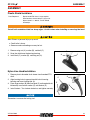
Plastic Shield Installaion
Cut-off knife on debris shield has sharp edges. Avoid contact when installing or removing line head.
Wear Gloves or personal injury may result:
◆ Cutoff knife is sharp.
◆ Gearcase and surrounding area may be hot.
1. Remove wing nut (A), washer (B), and bolt (C).
2. Snap the shield over the bearing housing.
3. Install bolt (C), washer (B), and wing nut (A).
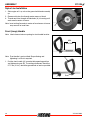
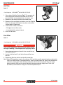
Nylon Line Head Installation
1. Remove plastic threaded shaft sleeve from threaded PTO
shaft.
2. Align locating hole in upper plate with hole in bearing
housing and insert locking tool (A).
3. Place large washer (B) then line head (C) on threaded shaft,
followed by small metal washer (D) and locknut (E).
4. Install locknut. Turn locknut clockwise, and tighten securely.
Remember to remove the locking tool.
Parts Required: Rapid LoaderTM Head, Large washer,
Small washer, 3/8-24 Locknut, (2) Pre-cut
Nylon Line 8 in. x .080 in., Plastic Shield
Assemblys.
A
B
C
A
B
C
E
D

14 X7722273204
© 04/2013 ECHO Inc.
ASSEMBLY GT-225
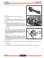
Nylon Line Installation
1. Shut engine off. Lay unit on the ground with head assembly
up.
2. Remove old nylon line through center recess of head.
3. Thread new lines through outside holes (A) in housing until
ends meet in center of recess.
Note: Insert cutting line ends to center of head recess to insure
easy removal of used lines.
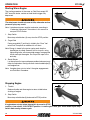
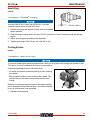
Front (Loop) Handle
Note: Label shows minimum spacing for front handle location.
Note: Front handle is pre-installed. Re-positioning and
tightening is all that is required.
1. Position front handle (A) in comfortable operating position
and tighten wing nut (B). The cutting attachment should be
5-7.5 cm (2-3 in.) above the ground and as level as possible.
A
MIN
SPACING
A
B

GT-225 OPERATION
X7722273204 15
© 04/2013 ECHO Inc.
OPERATION
Moving parts can amputate fingers or cause severe injuries. Keep hands, clothing and loose objects
away from all openings. Always stop engine, disconnect spark plug, and make sure all moving parts
have come to a complete stop before removing obstructions, clearing debris, or servicing unit.
Engine exhaust IS HOT, and contains Carbon Monoxide (CO), a poison gas. Breathing CO can cause
unconsciousness, serious injury, or death. Exhaust can cause serious burns. ALWAYS position unit
so that exhaust is directed away from your face and body.
Operation of this equipment may create sparks that can start fires. This unit is equipped with a spark
arrestor to prevent discharge of hot particles from the engine. Metal cutters can also create sparks if
the cutter strikes rocks, metal, or other hard objects. Contact local fire authorities for laws or
regulations regarding fire prevention requirements.
Fuel
Alternative fuels, such as E-15 (15% ethanol), E-85 (85% ethanol) or any fuels not meeting ECHO
requirements are NOT approved for use in ECHO 2-stroke gasoline engines. Use of alternative fuels
may cause performance problems, loss of power, overheating, fuel vapor lock, and unintended
machine operation, including, but not limited to, improper clutch engagement. Alternative fuels may
also cause premature deterioration of fuel lines, gaskets, carburetors and other engine components.
Fuel Requirements
Gasoline - Use 89 Octane [R+M/2] (mid grade or higher) gasoline known to be good quality. Gasoline may
contain up to 10% Ethanol (grain alcohol) or 15% MTBE (methyl tertiary-butyl ether). Gasoline containing
methanol (wood alcohol) is NOT approved.
Two Stroke Oil - A two-stroke engine oil meeting ISO-L-EGD (ISO/CD 13738) and J.A.S.O. FD
Standards
must be used. Echo brand premium Power Blend X
TM
Universal 2-Stroke Oil meets these standards. Engine
problems due to inadequate lubrication caused by failure to use an ISO-L-EGD (ISO/CD 13738) and
J.A.S.O. FD
certified oil, such as Echo premium Power Blend X
TM
, will void the two-stroke engine warranty.
Echo premium Power Blend X
TM
Universal 2-Stroke Oil may be mixed at 50:1 ratio for application in all Echo
engines sold in the past regardless of ratio specified in those manuals.
Handling Fuel
Fuel is VERY flammable. Use extreme care when mixing, storing or handling, or serious personal
injury may result.
• Use an approved fuel container.
• DO NOT smoke near fuel.

16 X7722273204
© 04/2013 ECHO Inc.
OPERATION GT-225
• DO NOT allow flames or sparks near fuel.
• Fuel tanks/cans may be under pressure. Always loosen fuel caps slowly allowing pressure to
equalize.
• NEVER refuel a unit when the engine is HOT or RUNNING!
• DO NOT fill fuel tanks indoors. ALWAYS fill fuel tanks outdoors over bare ground.
• DO NOT overfill fuel tank. Wipe up spills immediately.
• Securely tighten fuel tank cap and close fuel container after refueling.
• Inspect for fuel leakage. If fuel leakage is found, do not start or operate unit until leakage is
repaired.
• Move at least 3m (10 ft.) from refueling location before starting the engine.
Mixing Instructions
1. Fill an approved fuel container with half of the required
amount of gasoline.
2. Add the proper amount of 2-stroke oil to gasoline.
3. Close container and shake to mix oil with gasoline.
4. Add remaining gasoline, close fuel container, and remix.
Spilled fuel is a leading cause of hydrocarbon emissions. Some
states may require the use of automatic fuel shut-off containers
to reduce fuel spillage.
After use
• DO NOT store a unit with fuel in its tank. Leaks can occur. Return unused fuel to an approved fuel storage
container.
Storage - Fuel storage laws vary by locality. Contact your local government for the laws affecting your area.
As a precaution, store fuel in an approved, airtight container. Store in a well-ventilated, unoccupied building,
away from sparks and flames.
Stored fuel ages. Do not mix more fuel than you expect to use in thirty (30) days, ninety (90) days when a
fuel stabilizer is added.
Stored two-stroke fuel may separate. ALWAYS shake fuel container thoroughly before each use.
Starting Cold Engine
The attachment will operate immediately when the engine starts, and could result in possible
serious injury. Keep movable parts of the attachment away from objects that could become
entangled or thrown, and surfaces that could cause loss of control.

GT-225 OPERATION
X7722273204 17
© 04/2013 ECHO Inc.
1. Stop Switch
Move stop switch button (A) away from the STOP position.
2. Choke
Move choke lever (B) to Cold Start Position ( ).
3. Purge Bulb
Pump purge bulb (C) until fuel is visible and flows freely in the
clear fuel tank return line. Pump bulb an additional 4 or 5
times.
Note: Energy is stored in the starter spring each time the
handle/rope is pulled. Generally two to six pulls, using
light pulling force, will store enough energy to engage the
starter and spin the engine. Do not pull the rope out to
end stop.
4. Recoil Starter
Lay the unit on a flat area and keep movable attachment parts
clear of all obstacles. Firmly grasp throttle grip with left hand
and fully depress throttle trigger to wide open position. Gently
pull recoil starter handle/rope (D) until engine fires or 2 to 3
engine engagements.
5. Choke
After engine fires, or 2 to 3 engine engagements , move choke
lever (B) to the Run position ( ). Hold throttle trigger fully
depressed and pull starter handle/rope until engine starts and
runs. Release throttle trigger and allow unit to warm up at idle
for several minutes.
Note: If engine does not start with choke in “Run” position after 2-3 engine engagements, repeat instructions
2 - 5.
6. Throttle Trigger
After engine warm-up, gradually depress throttle trigger to increase engine RPM to operating speed.
A
B
C
D

18 X7722273204
© 04/2013 ECHO Inc.
OPERATION GT-225
Starting Warm Engine
The starting procedure is the same as Cold Start except DO
NOT close the choke, and do not hold throttle trigger fully
depressed.
The attachment should not move at idle, otherwise serious
personal injury may result.
Note: If attachment moves, readjust carburetor according to
“Carburetor Adjustment” instructions in this manual or
see your ECHO Dealer.
1. Stop Switch
Move stop switch button (A) away from the STOP position.
2. Purge Bulb
Pump purge bulb (C) until fuel is visible in the “Clear” fuel
return line. Pump bulb an additional 4 or 5 times.
Note: Energy is stored in the starter spring each time the
handle/rope is pulled. Generally two to six pulls, using
light pulling force, will store enough energy to engage the
starter and spin the engine. Do not pull the rope out to
end stop.
3. Recoil Starter
Lay the unit on a flat area and keep movable attachment parts
clear of all obstacles. Gently pull recoil starter handle/rope (D)
until engine fires.
Note: If engine does not start after 2-3 engine engagements,
use Cold Start Procedure.
Stopping Engine
1. Throttle
Release throttle and allow engine to return to idle before
shutting off engine.
2. Stop Switch
Move stop switch button(A) backward to STOP position.
If engine does not stop when stop switch is moved to STOP
position, close choke - COLD START position - to stall engine. Have your ECHO dealer repair stop
switch before using trimmer again.
A
C
C
D
A

GT-225 MAINTENANCE
X7722273204 19
© 04/2013 ECHO Inc.
MAINTENANCE
Moving parts can amputate fingers or cause severe injuries. Keep hands, clothing and loose objects
away from all openings. Always stop engine, disconnect spark plug, and make sure all moving parts
have come to a complete stop before removing obstructions, clearing debris, or servicing unit.
Allow unit to cool before performing service. Wear gloves to protect hands from sharp edges and
hot surfaces.
Your ECHO unit is designed to provide many hours of trouble free service. Regular scheduled maintenance
will help your unit achieve that goal. If you are unsure or are not equipped with the necessary tools, you may
want to take your unit to an ECHO Service Dealer for maintenance. To help you decide whether you want to
DO-IT-YOURSELF or have the ECHO Dealer do it, each maintenance task has been graded. If the task is
not listed, see your ECHO Dealer for repairs.
Skill Levels
Level 1 = Easy to do. Common tools may be required.
Level 2 = Moderate difficulty. Some specialized tools may be required.
ECHO offers REPOWER
TM
Maintenance Kits and Parts to make your maintenance job easier.
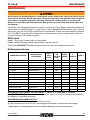
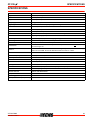
Maintenance Intervals
MAINTENANCE PROCEDURE LETTER CODES: I = INSPECT, R = REPLACE, C = CLEAN
IMPORTANT NOTE - Time intervals shown are maximum. Actual use and your experience will determine
the frequency of required maintenance.
MAINTENANCE PROCEDURE NOTES:
(1) Apply POWER BLENDX
TM
grease every 25 hours of use.
(2) Low evaporative fuel tanks DO NOT require regular maintenance to maintain emission integrity.
* Replacement is recommended based on the finding of damage or wear during inspection.
COMPONENT/SYSTEM
MAINTENANCE
PROCEDURE
REQ’D
SKILL
LEVEL
DAILY
OR
BEFORE
USE
EVERY
REFUEL
3
MONTHS
YEARLY
Air Filter Inspect/Clean 1I / C * R *
Choke Shutter Inspect/Clean 1 I / C
Fuel Filter Inspect/Replace 1I * I / R *
Fuel Cap Gasket Inspect/Replace 1I * R *
Fuel System Inspect/Replace 1 I (2) * I (2) *
Spark Plug Inspect/Clean/Replace 1 I / C / R *
Cooling System Inspect/Clean 2 I / C
Muffler Spark Arrestor Inspect/Clean/Replace 2 I / C / R *
Cylinder Exhaust Port Inspect/Clean/Decarbon 2I / C
Drive Shaft Inspect/Grease 2I (1)
Gear Housing None
Recoil Starter Rope Inspect/Clean 1I / C *
Screws/Nuts/Bolts Inspect/Tighten/Replace 1I *

20 X7722273204
© 04/2013 ECHO Inc.
MAINTENANCE GT-225
Air Filter
Level 1.
1. Close choke (Cold Start Position [ ]). This prevents dirt
from entering the carburetor throat when the air filter is
removed. Brush accumulated dirt from air cleaner area.
2. Remove air filter cover. Brush dirt from inside cover.
3. Remove air filter and lightly brush debris from filter. Replace
filter if it is damaged, fuel soaked, very dirty, or the rubber
sealing edges are deformed.
4. If filter can be reused, be certain it:
• Fits tightly in the air filter cavity.
• Is installed with the original side out.
5. Install air filter cover.
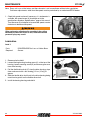
Fuel Filter
Level 1.
Fuel is VERY flammable. Use extreme care when mixing,
storing or handling, or serious personal injury may result.
1. Use a clean rag to remove loose dirt from around fuel cap
and empty fuel tank.
2. Use the “fuel line hook” to pull the fuel line and filter from
the tank.
3. Remove the filter from the line and install the new filter.
Note: Federal EPA regulations require all model year 2012 and later gasoline powered engines produced for
sale in the United States to be equipped with a special low permeation fuel supply hose between the
carburetor and fuel tank. When servicing model year 2012 and later equipment, only fuel supply
hoses certified by EPA can be used to replace the original equipment supply hose. Fines up to
$37,500 may be enforced for using an un-certified replacement part.
Parts Required:
REPOWER
TM
AIR & FUEL FILTER KIT.
Parts Required:
REPOWER
TM
AIR & FUEL FILTER KIT.
Page is loading ...
Page is loading ...
Page is loading ...
Page is loading ...
Page is loading ...
Page is loading ...
Page is loading ...
Page is loading ...
Page is loading ...
Page is loading ...
Page is loading ...
Page is loading ...
-
 1
1
-
 2
2
-
 3
3
-
 4
4
-
 5
5
-
 6
6
-
 7
7
-
 8
8
-
 9
9
-
 10
10
-
 11
11
-
 12
12
-
 13
13
-
 14
14
-
 15
15
-
 16
16
-
 17
17
-
 18
18
-
 19
19
-
 20
20
-
 21
21
-
 22
22
-
 23
23
-
 24
24
-
 25
25
-
 26
26
-
 27
27
-
 28
28
-
 29
29
-
 30
30
-
 31
31
-
 32
32


Ask a question and I''ll find the answer in the document
Finding information in a document is now easier with AI