Hifonics Zxi 08 Owner's manual
- Category
- Car audio amplifiers
- Type
- Owner's manual
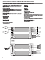
Hifonics Zxi 08 is a high-performance amplifier with a wide range of features that make it a great choice for any car audio system. With variable crossovers, subsonic filter, bass equalization, and a remote bass control module (some models), you can customize the sound to your liking. The built-in diagnostic mode will protect your amplifier from damage by detecting shorted speaker leads, low impedance, dangerous high temperatures, and DC shorts. Whether you're looking for a powerful amp for your home stereo or a way to upgrade your car's sound system, Hifonics Zxi 08 is a great option.
Hifonics Zxi 08 is a high-performance amplifier with a wide range of features that make it a great choice for any car audio system. With variable crossovers, subsonic filter, bass equalization, and a remote bass control module (some models), you can customize the sound to your liking. The built-in diagnostic mode will protect your amplifier from damage by detecting shorted speaker leads, low impedance, dangerous high temperatures, and DC shorts. Whether you're looking for a powerful amp for your home stereo or a way to upgrade your car's sound system, Hifonics Zxi 08 is a great option.


-
 1
1
-
 2
2
-
 3
3
-
 4
4
-
 5
5
-
 6
6
-
 7
7
-
 8
8
-
 9
9
-
 10
10
-
 11
11
-
 12
12
-
 13
13
-
 14
14
-
 15
15


Hifonics Zxi 08 Owner's manual
- Category
- Car audio amplifiers
- Type
- Owner's manual
Hifonics Zxi 08 is a high-performance amplifier with a wide range of features that make it a great choice for any car audio system. With variable crossovers, subsonic filter, bass equalization, and a remote bass control module (some models), you can customize the sound to your liking. The built-in diagnostic mode will protect your amplifier from damage by detecting shorted speaker leads, low impedance, dangerous high temperatures, and DC shorts. Whether you're looking for a powerful amp for your home stereo or a way to upgrade your car's sound system, Hifonics Zxi 08 is a great option.
Ask a question and I''ll find the answer in the document
Finding information in a document is now easier with AI
Related papers
-
Hifonics ZXI Zeus User manual
-
 Brutus Power Pro 1100 Owner's manual
-
-
-
-
-
-
-
-

Other documents
-
MB QUART RA2000.1 User manual
-
Crunch GP1600 Owner's manual
-
-
-
Maxxsonics Pseries PowerZone User manual
-
-
-
-
Crunch p1-5050.5 User manual
-