Page is loading ...

ASPII / MDII SERIES
LT33 (0208)
P.O. Box 10
5000 W. 106th Street
Zionsville, Indiana 46077
Phone (317) 733-2133
Fax (317) 873-1105
www.dartcontrols.com
Instruction Manual
CONTROLS
A-5-3067H
PROGRAMMABLE DIGITAL CLOSED LOOP DC MOTOR
SPEED CONTROL with P-I-D algorithm and serial communications
Re-Order from
omegamation.com
Omegamation
TM
1-888-55-OMEGA
1-888-55-66342
1-888-55-66342

TABLE OF CONTENTS
1
WARRANTY ------------------------------------------------------------------------------------------------------------------ 2
OVERVIEW OF THE MDII / ASPII ------------------------------------------------------------------------------------- 3
FEATURES ----------------------------------------------------------------------------------------------------------------- 3-4
SPECIFICATIONS ---------------------------------------------------------------------------------------------------------- 5
DIMENSION CHART ------------------------------------------------------------------------------------------------------- 5
JUMPERS, SERIAL CONNECTOR & TERMINAL STRIP ACCESS ----------------------------------------- 6
MOUNTING GASKET INSTALLATION ----------------------------------------------------------------------------- 6
INSTALLATION ----------------------------------------------------------------------------------------------------------- 7-8
PU-E SERIES INSTALLATION ---------------------------------------------------------------------------------------- 8
WIRING DIAGRAMS -------------------------------------------------------------------------------------------------- 9-10
HOOK-UP DIAGRAMS -------------------------------------------------------------------------------------------------- 11
INITIAL CHECK-OUT OF THE ASPII / MDII ---------------------------------------------------------------------- 12
OPERATING THE ASPII / MDII --------------------------------------------------------------------------------------- 13
CUSTOMIZING OPERATING PARAMETERS - OVERVIEW ------------------------------------------------ 14
FRONT PANEL CUSTOMIZING OF OPERATING PARAMETERS ---------------------------------- 14-15
RESETTING FACTORY DEFAULTS ------------------------------------------------------------------------------- 16
CUSTOMIZING P-I-D ----------------------------------------------------------------------------------------------------- 16
ASPII/MDII MENU TREE FLOWCHART -------------------------------------------------------------------------- 17
DISPLAY INTERPRETATIONS -------------------------------------------------------------------------------------- 18
USING THE ANALOG INPUT ON THE MDII ---------------------------------------------------------------- 18-22
OVERVIEW -------------------------------------------------------------------------------------------------------- 19
TYPES OF SIGNAL SOURCES ----------------------------------------------------------------------- 19-20
ROUTING OF ANALOG SIGNALS ------------------------------------------------------------------------ 20
FIELD CUSTOMIZING ------------------------------------------------------------------------------------ 21-22
HOOKING IT UP ------------------------------------------------------------------------------------------------- 22
TROUBLESHOOTING GUIDE ---------------------------------------------------------------------------------------- 23
USING THE FREQUENCY GENERATOR OUTPUT ----------------------------------------------------------- 24
USER-ASSIGNABLE OUTPUT --------------------------------------------------------------------------------------- 25
USER-ASSIGNABLE OUTPUT LOGIC DIAGRAMS ---------------------------------------------------------- 26
SETTING SOFTSWITCHES -------------------------------------------------------------------------------------------- 27
COMMUNICATIONS & NETWORKING ----------------------------------------------------------------------- 28-34
COMMONLY USED SOFTWARE -------------------------------------------------------------------------- 28
HARDWARE - JUMPER SELECTION --------------------------------------------------------------- 28-29
RS232 & RS422/RS485 CONNECTIONS TO THE RJ45 MODULAR JACK ------------- 29-30
SOFTWARE - DATA FORMAT ----------------------------------------------------------------------------- 31
FORMAT FOR MESSAGES---------------------------------------------------------------------------------- 32
DIRECT COMMANDS FROM A COMPUTER / PLC -------------------------------------------- 33-34
DOWNLOADING DATA BETWEEN TWO UNITS -------------------------------------------------------------- 34
APPENDIX ------------------------------------------------------------------------------------------------------------- 35-39
DESCRIPTION OF ITEM FUNCTIONS -------------------------------------------------------------- 35-37
INDEX TO THE ASPII / MDII MEMORY-------------------------------------------------------------- 38-39
GLOSSARY ------------------------------------------------------------------------------------------------------------ 40-42
REPAIR PROCEDURE & PRODUCT LINE ----------------------------------------------------- BACK COVER

2
WARRANTY
Dart Controls, Inc. (DCI) warrants its products to be free from defects in material and
workmanship. The exclusive remedy for this warranty is DCI factory replacement of any
part or parts of such product which shall within 12 months after delivery to the purchaser
be returned to DCI factory with all transportation charges prepaid and which DCI
determines to its satisfaction to be defective. This warranty shall not extend to defects
in assembly by other than DCI or to any article which has been repaired or altered by
other than DCI or to any article which DCI determines has been subjected to improper
use. DCI assumes no responsibility for the design characteristics of any unit or its
operation in any circuit or assembly. This warranty is in lieu of all other warranties,
express or implied; all other liabilities or obligations on the part of DCI, including
consequential damages, are hereby expressly excluded.
CAREFULLY CHECK THE CONTROL FOR SHIPPING DAMAGE. REPORT ANY
DAMAGE TO THE CARRIER IMMEDIATELY. DO NOT ATTEMPT TO OPERATE
THE DRIVE IF VISIBLE DAMAGE IS EVIDENT TO EITHER THE CIRCUIT OR TO
THE ELECTRONIC COMPONENTS.
All information contained in this manual is intended to be correct, however information
and data in this manual are subject to change without notice. DCI makes no warranty
of any kind with regard to this information or data. Further, DCI is not responsible for any
omissions or errors or consequential damage caused by the user of the product. DCI
reserves the right to make manufacturing changes which may not be included in this
manual.
IMPROPER INSTALLATION OR OPERATION OF THIS CONTROL MAY
CAUSE INJURY TO PERSONNEL OR CONTROL FAILURE. THE CON-
TROL MUST BE INSTALLED IN ACCORDANCE WITH LOCAL, STATE,
AND NATIONAL SAFETY CODES.
WARNING
MAKE CERTAIN THAT THE POWER SUPPLY IS DISCONNECTED BEFORE
ATTEMPTING TO SERVICE OR REMOVE ANY COMPONENTS!!! IF THE POWER
DISCONNECT POINT IS OUT OF SIGHT, LOCK IT IN DISCONNECTED POSITION
AND TAG TO PREVENT UNEXPECTED APPLICATION OF POWER.
ONLY A QUALIFIED ELECTRICIAN OR SERVICE PERSONNEL SHOULD PERFORM
ANY ELECTRICAL TROUBLESHOOTING OR MAINTENANCE.
AT NO TIME SHOULD CIRCUIT CONTINUITY BE CHECKED BY SHORTING
TERMINALS WITH A SCREWDRIVER OR OTHER METAL DEVICE.
WARNING

3
Overview of the MDII / ASPII
OVERVIEW:
MDII: The Micro Drive II series digital motor speed controls employ an advanced 16-bit microprocessor. The
MD20P is designed for digital closed-loop operation of up to 1/2 horsepower DC permanent magnet motors,
while the MD30P and MD30E range is from 1/4 through 2 horsepower. This control features a true P-I-D
algorithm, with user-programmable gains for extremely responsive and precise control over a wide variety of
desired speeds and applications. Set or Actual speed is displayed directly in RPM, Process Time, or other
engineering units. Field customizing permits setting of specific operating parameters. The MD20P and MD30P
offer improved performance over the MD10P and MD3P respectively and come in the same 1/8 DIN and 1/
4 DIN sizes. Both sizes are rated to NEMA 4X when properly installed in a panel. The MD30E offers the same
electrical features as the MD30P in a wall mount NEMA 4/12 enclosure.
ASPII: The Accu-Set II is a device which allows conventional AC and DC motor drives to be operated in
a digital closed loop configuration. By simply replacing the conventional 3-wire speed pot of the drive,
closed loop operation is achieved. This configuration provides for extremely tight control of motor speed.
The ASP20 control features a true P-I-D algorithm with user definable parameters for extremely responsive
and precise control over a wide variety of desired speeds and applications. Set or Actual speed may be
displayed directly in RPM, Process Time, or other engineering units. Field customizing permits setting of
specific operating parameters. The ASP20 is a companion to, or replacement for, the ASP10 and offers
significantly improved performance over the ASP10. The ASP20 is compatible with most drives having a
supply voltage of 3 - 24VDC and an input impedance of 1,000 to 10,000,000 ohms. Output inversion allows
the ASP20 to operate with drives that use a negative voltage supply. The ASP20 comes in a NEMA 4X 1/
8 DIN panel mount package.
ASPII / MDII: The integrated RS485/422/232 serial interface port is ideal for monitoring/control using
almost any computer or process controller. Units can even be attached in a Local Area Network, and can
then be controlled and even customized either individually or all at once. “Multi” mode allows the user to
choose between a “menu” of up to six programmed configurations, if desired.
FEATURES:
• Compact NEMA 4X 1/8 or 1/4DIN sturdy housing for panel mounting; or NEMA 4/12 wall mount
enclosure.
• Microprocessor based; utilizes powerful 16-bit Motorola MC68HC11
• Field Programmable operating parameters
• Displays actual or desired speed directly in RPM, FPM, process time, or other engineering units
• P-I-D digital closed loop control; gains setable for optimum system performance; Fast settling time
• Accuracy ± 1 RPM of set speed
• Master/Follower operation
• Accepts a variety of pick-up inputs; hall-effect, photoelectric, TTL, or any open collector NPN capable
of sinking 2.5mA; control accepts 1 to 1.2 million pulses per minute
• Internal A/D interface permits using potentiometer, 4 to 20mA or 0 to +5 VDC signal in lieu of digital
pick-up signal or to control target speed, current program or frequency generator output
• Non-volatile memory retains speed setting and all field programmable parameters
• Inhibit circuit permits start and stop without breaking AC lines; pre-selecting speed, or simultaneous
start-up of multiple control units
• Up/down pushbuttons for set points - slow-fast sweep
• Self-contained power supply for transducer (+5V, 25mA)
• Exclusive user assignable output - to drive relays, alarms, etc. Can be activated by any combination of
conditions; upper speed limit exceeded, etc.
• Independent frequency generator allows units to produce their own leader frequency
(continued on following page)

• European-style terminal block standard (Pluggable version available)
• G.E. Lexan™ membrane seals faceplate from environment
• Multi-mode of operation allows multiple constants, settings, and upper/lower limits. Up to six differ-
ent configurations can be selected from the front panel via the up/down pushbutton switches
• Programmable stall detector sets minimum acceptable speed for annunciation or shutdown
• Selectable front panel “Lockout” or hardware lockout can be used to prevent accidental or unauthorized
changes
Programming features:
All customizing can be done from the front panel. Simple “menu-driven” operation for selecting/
viewing/editing of all field parameters
User-selectable “programming protect” to prevent unwanted access to field customizing functions.
A wide assortment of operating parameters or “items” can be customized, including:
• Display Scalars to allow control/display in user “Engineering Units”. Up to 6 different Scalars
can be programmed in “Multi” mode
• Desired speed setting. Up to 6 different desired settings can be programmed in “Multi” mode
• Lower/Upper limits for speed setting. Up to 6 different limit pairs can be programmed in
“Multi” mode
• Individual P-I-D gain settings
• Separate Acceleration and Deceleration times
• Stall Detect Timeout
• Displayed decimal point, or colon displayed automatically in process time mode. Up to 6 differ-
ent decimal point locations can be programmed in “Multi” mode
• Selectable display blanking point. Up to 6 different blanking positions can be programmed in
“Multi” mode
• Selectable display modes. Can be set to display the following:
Desired “target” speed (or time)
Actual speed (or time) “tach”
Program name (each name can have up to 4 characters)
• Operation Mode (Master Rate, Master Time, Standard Follower {rate})
• Frequency Generator rate
• Front Panel Lockout for Speed setting and/or “program” selection
• In “Multi” mode, you can select whether the speed setting is “attached” to each program, or
whether the speed remains the same when selecting a new program
• Four LED function indicators make operating and customizing easy
Communications features:
• RS485; RS422; RS232 serial interface port for remote monitoring/control/programming allows the
following:
- Continuous output of actual shaft speed
- Remote speed setting
- Programming or listing of all field programmable parameters
- Dartnet network allows multiple controls to be attached via one cable. Controls can be individ-
ually programmed or integrated
- Programmable communication baud rate for 300 to 9600 buad
(continued)
4

Specifications
AC Input Voltage ------------------------------------------------------------------------------------ 85 - 265VAC
Input Frequency ----------------------------------------------------------------------------------------- 50/60 Hertz
Operating Ambient Temperature Range ----------------------------------------- -10
o
to 45
o
C (14
o
to 113
o
F)
Overload Capacity ---------------------------------------------------------------------------- 200% for 1 Minute*
Service Factor ------------------------------------------------------------------------------------------------------ 1.0
Efficiency --------------------------------------------------------------------------------------------- 85% Typical*
Output Voltage ------------------------------------- 0-90VDC@120VAC IN / 0-180VDC @240VAC IN**
Maximum Output Current ----------------------------------- 5ADC (MD20P); 10ADC (MD30P, MD30E)*
Minimum Output Current ----------------------------------------------------------------------------- 150mA DC*
Maximum Horsepower Rating -------------------------------- 1/2 h.p. (MD20P); 1 h.p. (MD30P, MD30E)*
Accel/Decel Time ------------------------------------------------------ 0 to 30 seconds for a 1000RPM Change
Serial Interface -------------------------------------------------------------------------------------- RS232/422/485
Baud Rate --------------------------------------------------------------- Selectable 300, 1200, 2400, 4800, 9600
Analog Input Voltage Range --------------------------------------------------------------------------- 0 to 5VDC
Motor Pick-up Input Rate ------------------------------------ 10 to 1.2M Pulses Per Minute (.167 to 20KHz.)
Leader Signal Input Rate ------------------------------------- 10 to 1.2M Pulses Per Minute (.167 to 20KHz.)
Stall Detector ------------------------------------------------------------ Banner Message and Output Shutdown
Frequency Generator Output Rate ---------------------------------------------------- 0-9999 Pulses per Minute
Frequency Generator Accuracy -------------------------------------------------------------- ± .7% of Full Scale
Update Time ---------------------------------------------------------------------------------------------------- 32 mS
Connection Type ---------------------------- European-Style Terminal Block (Pluggable Version Available)
Faceplate Material --------------------------------------------------- Polycarbonate with GE Lexan™ Overlay
Power Supply for Transducer -------------------------------------------------------------------- +5 VDC, 25mA
Supply Voltage applied across output (ASP20 only) ----------------------------------------------- 3 to 24VDC
Input Impedance of Driven unit (ASP20 only) ----------------------------------------------- 1K to 10M Ohms
Weight ------------------------------------------- MD20P - 14.72 oz. (417.3g); MD30P - 24.64 oz. (698.52g);
-------------------------------------------------------- MD30E - 32.2 oz. (910g); ASP20 - 15.04 oz. (426.37g).
Dimension Chart
* Does not apply to ASPII Series
** Maximum Motor Output Voltage will be peak AC Input Voltage.
5
Housing 3.62 1.66 4.625
Lens 4.539 2.289 0.375
Housing 91.94 42.16 117.27
Lens 115.28 58.14 9.53
Housing 3.60 3.497 4.625
Lens 4.539 4.179 0.375
Housing 91.44 88.82 117.27
Lens 115.28 106.15 9.53
Model Width Height Depth
MD20P/ASP20 English (inches)
MD20P/ASP20 Metric (millimeters)
MD30P English (inches)
MD30P Metric (millimeters)
Assembly 5.53 7.40 3.90
MD30E English (inches)
MD30E Metric (millimeters)
Assembly 140.46 187.96 99.06

6
Jumpers, Serial Connector and Terminal Strip Access
See “MD30E INSTALLATION” section for internal access of MD30E.
See “COMMUNICATION AND NETWORKING” section for
location of Jumpers, Serial Connector and Terminal Strip Access.
Mounting Gasket Installation
LIFT UP TOP COVER OVER
ENDPLATE AND SLIDE
BACKWARDS TO EXPOSE
INTERNAL CONTROL AND
TERMINAL BLOCK
PANEL MOUNTING GASKET
(WITH THE ADHESIVE SIDE OF
GASKET FACING THE CUSTOMER
MOUNTING PANEL)
CUSTOMER
MOUNTING PANEL
(HOLE CUT-OUT FOR CONTROL
HOUSING APPROXIMATELY
3.622" WIDE BY 1.770" HIGH)
ASPII / MDII
SERIES CONTROL
SUPPLIED WITH EACH CONTROL:
1) GASKET
2) (2) 6-32 X 3/4 PANHEAD BLACK OXIDE STAINLESS SCREWS
3) (2) #6 NUT WITH LOCKWASHER

7
Installation
ASP20 / MD20P/30P INSTALLATION
STEP 1. Cut appropriate hole in panel using the following diagrams.
STEP 2. Mount the control into panel cut-out.
STEP 3. Secure control to panel. The control itself may be used as a template for hole location. The two (ASP20/MD20)
or four (MD30) mounting holes have a diameter of .160 in. Use the supplied #6 hardware to fasten to the panel.
Be careful not to over tighten mounting bolts.
3.622"
HOUSING DEPTH
4.625"
PANEL CUT-OUT
MD30P
3.622"
MICRO-DRIVE II
ENTER
Tach
Item
ValuPage
4.000"
4.000"
Dia .140" x 4
.811"
2.000"
CONTROLS
Tach
Ite
ValPage
Tach
Ite
m
ValuPage
MICRO-DRIVE
3.622"
HOUSING DEPTH
4.625"
PANEL CUT-OUT
.885"
ASP20 / MD20P
ACCU-SET II
ENTER
CONTROLS
4.000"
Tach
Item
ValuPage
4.000"
Dia .140" x 2
1.770"

dust
cover
10-32
screw
magnet
disc
flat
washer
PU-E
bearing
3/16"
spacer
tapped
motor
shaft
black wire
common
white wire
signal
red wire
+5 volts
5.500
.750
5.125 TYP.
7/32" TYP.
(4 SLOTS)
.350 DEEP
5.530
Tach
Item
ValuPage
ON
OFF
7.400
CONTROLS
ENTER
PU-E Series Installation
8
MD30E INSTALLATION
STEP 1.
Mount the MD30E to the panel using
the appropriate hardware in the four
7/32" mounting slots (the control may
be used as a mounting template for
hole placement).
STEP 2.
Remove the four (4) #6 screws that
attach the cover to the aluminum ex-
trusion.
STEP 3.
Wire the control to the motor, pick-
up, AC line and any communica tions/
analog inputs that are to be used in
your application. Run your wiring
through the 1/2" NPT endplate con
duit holes, located at the terminal
strip end of the control housing.
CAUTION: DO NOT OVER TIGHTEN MOUNTING SCREW !!
PULSES PER
REVOLUTION
MODE
PU-2E
PU-4E
PU-10E
PU-20E
1
2
5
10
No other mounting screws are necessary, as the cord will keep the
unit from rotating. The PU-E gives a high signal when the north pole
of the magnetic disc crosses the Hall-Effect transistor. The signal is
switched low when the south pole crosses this same transistor.
Dimensions
The Dart PU-E series pick-up is an economical way to monitor motor speed. Its patented design provides for ease of
installation in otherwise difficult to reach areas. The PU-E operates from the +5V power supply in the MDII/ASPII,
producing a 5 volt square wave whose frequency is proportional to speed. This signal is fed into the control as a speed
reference for the microprocessor.
CAUTION: THE PU-E CORD SHOULD NOT BE GROUPED WITH ANY OTHER WIRES OR CORDS. FOR APPLI-
CATIONS WITH PU-E WIRE OVER 6 FEET LONG, OR NOISY ENVIRONMENTS, A SHIELDED CABLE IS REC-
OMMENDED. CONNECT THE SHIELD TO THE COMMON TERMINAL ON THE MDII/ASPII, LEAVING THE
SHIELD ON THE PU-E END FLOATING.
72.00
2.40
1.60 .875

PICK-UP MOUNTED
TO MOTOR SHAFT
AC INPUT
AC INPUT
black
white
red
P1-1
P1-2
P1-3
P1-4
P1-5
P1-6
P1-7
P1-8
MDII
MASTER
* MD20P = 7.5 Amp
MD30P = 15 Amp
FUSE*
MOTOR
-ARM
+ARM
COMMON
+5VDC
SIGNAL 1
OPTIONAL
INHIBIT
SWITCH
(Mounts on rotating
end shaft with 10-32
tapped hole, 1/2" deep)
P1-9
P1-10
P1-11
P1-12
}
85-265VAC
UNUSED
UNUSED
UNUSED
UNUSED
P1-1
P1-2
P1-3
P1-4
P1-5
P1-6
P1-7
P1-8
P1-9
P1-10
P1-11
P1-12
MDII
FOLLOWER
AC INPUT
AC INPUT
FUSE*
MOTOR
-ARM
+ARM
UNUSED
UNUSED
UNUSED
FOLLOWER PICK-UP
MOUNTED TO
MOTOR SHAFT
black
white
red
(Mounts on rotating
end shaft with 10-32
tapped hole, 1/2" deep)
COMMON
+5VDC
SIGNAL 1
}
85-265VAC
UNUSED
* MD20P = 7.5 Amp
MD30P = 15 Am
p
OPTIONAL
INHIBIT
SWITCH
white
black
9
Wiring Diagrams
MDII SERIES WIRING DIAGRAM - STANDARD LEADER ONLY
MDII SERIES WIRING DIAGRAM -
STANDARD FOLLOWER
STEP 1: Connect the proper input voltage to P1-1 and P1-2. NOTE: On MD20P and MD30P, fusing should be added in AC line
to protect the control.
STEP 2: With AC power off, connect the PU-E as shown in hook-up diagram.
STEP 3: Connect motor by attaching -Arm to P1-3 and +Arm to P1-4.
STEP 4: Connect pick-up as shown.
STEP 5: You are now ready to apply power to your system. If the motor is rotating in the wrong direction, turn power off and reverse
the armature leads.
NOTE: SHIELDED CABLE IS RECOMMENDED FOR APPLICATIONS WHERE PICK-UP CORD LENGTH IS IN EXCESS OF
6 FEET. Connect the shield to the common terminal of the MDII, leaving the shield at the pick-up end "floating".
CAUTION: When master pick-up signal “A” is lost, the master MDII will run at full speed, while the follower MDII will go
to zero speed. If the follower pick-up signal “B” is lost, the follower MDII will run at full speed and the
master will be unaffected.
WARNING !
DO NOT ATTEMPT TO PERFORM A HI-POT TEST ACROSS AC LINES WITH THE CONTROL IN CIRCUIT.
THIS WILL RESULT IN IMMEDIATE OR LONG TERM DAMAGE TO THE CONTROL.

PICK-UP MOUNTED
TO MOTOR SHAFT
AC INPUT
AC INPUT
black
white
red
P1-1
P1-2
P1-3
P1-4
P1-5
P1-6
P1-7
P1-8
ASP20
MASTER
2 Amp
FUSE
COMMON
+5VDC
SIGNAL 1
(Mounts on rotating
end shaft with 10-32
tapped hole, 1/2" deep)
P1-9
P1-10
P1-11
P1-12
}
85-265VAC
SIGNAL 2
}
See Output
Connection
Note Below
HIGH OUT
WIPER OUT
LOW OUT
* OPTIONAL INHIBIT
SWITCH
(Open = Run)
(Closed = Inhibit)
*
UNUSED
UNUSED
UNUSED
}
See Output
Connection
Note Below
HIGH OUT
WIPER OUT
LOW OUT
P1-1
P1-2
P1-3
P1-4
P1-5
P1-6
P1-7
P1-8
P1-9
P1-10
P1-11
P1-12
ASP20
FOLLOWER
AC INPUT
AC INPUT
2 Amp
FUSE
FOLLOWER PICK-UP
MOUNTED TO
MOTOR SHAFT
black
white
red
(Mounts on rotating
end shaft with 10-32
tapped hole, 1/2" deep)
COMMON
+5VDC
SIGNAL 1
}
85-265VAC
SIGNAL 2
* OPTIONAL INHIBIT
SWITCH
(Open = Inhibit)
(Closed = Run)
*
UNUSED
UNUSED
UNUSED
black
white
10
Wiring Diagrams
NOTE: SHIELDED CABLE IS RECOMMENDED FOR APPLICATIONS WHERE PICK-UP CORD LENGTH IS
IN EXCESS OF 6 FEET. Connect the shield to the common terminal of the ASP20, leaving the shield at
the pick-up end floating.
CAUTION: When master pick-up signal “A” is lost, the master ASP20 will run at full speed, while the follower
ASP20 will go to zero speed. If the follower pick-up signal “B” is lost, the follower ASP20 will run at full
speed and the master will be unaffected.
HOOK-UP PROCEDURE:
STEP 1: Connect the proper input voltage to P1-1 and P1-2. NOTE: Fusing should be added in the AC line to protect
the control. A 2 amp fuse is recommended.
STEP 2: Connect the PU-E as shown in hook-up diagram above.
STEP 3: Wire the pot output of the ASP20 to the control being driven.
STEP 4: You are now ready to apply power to your system.
STEP 5: Turn IR Comp, Accel and Decel to full off position on driven control unit.
OUTPUT CONNECTION NOTE:
Connect to Speedpot input of the device being driven (P1-3 must be positive in respect to P1-5). If driven device has
a positive supply, connect P1-3 to the Positive supply terminal (Pot High) and set Page 7 Item 11 to a value of zero.
If driven device has a negative power supply, connect P1-3 to the Common terminal (Pot Low) and set Page 7 Item
11 to a value of 1.
ASPII SERIES WIRING DIAGRAM
- STANDARD FOLLOWER
ASPII SERIES WIRING DIAGRAM - STANDARD LEADER ONLY

11
MD30E HOOK-UP
MD30E-7 HOOK-UP
P1
BROWN
BLUE
YELLOW
GREEN
RED
BLACK
ORANGE
GREY
RS422/485 Data in (P9-3)
+5VDC (P9-2)
RS232 Receive Data (P9-1)
RS422/485 Data out (P9-4)
Analog Signal Input (P9-7)
Common (P9-6)
Freq. Gen. (P9-5)
RS232 Transmit Data (P9-8)
P1-12
AC INPUT
AC INPUT
FUSE
MOTOR
-ARM
+ARM
UNUSED
UNUSED
UNUSED
FOLLOWER PICK-UP
MOUNTED TO
MOTOR SHAFT
black
white
red
(Mounts on rotating
end shaft with 10-32
tapped hole, 1/2" deep)
MASTER PICK-UP
MOUNTED TO
MOTOR SHAFT
(Mounts on rotating
end shaft with 10-32
tapped hole, 1/2" deep)
black
white
red
COMMON
+5VDC
SIGNAL 1
}
85-265VAC
UNUSED
OPTIONAL
INHIBIT
SWITCH
P1-11
P1-10
P1-9
P1-8
P1-7
P1-6
P1-5
P1-4
P1-3
P1-2
P1-1
MD30E Hook-Up Diagrams
P1-12
P1-11
P1-4
P1-5
P1-6
P1-7
P1-8
P1-9
P1-10
P1-3
P1-2
P1-1
PICK-UP MOUNTED
TO MOTOR SHAFT
AC INPUT
AC INPUT
black
white
red
FUSE
MOTOR
-ARM
+ARM
COMMON
+5VDC
SIGNAL 1
OPTIONAL
INHIBIT
SWITCH
(Mounts on rotating
end shaft with 10-32
tapped hole, 1/2" deep)
}
85-265VAC
UNUSED
UNUSED
UNUSED
COM (P1-5)
UNUSED

12
Initial Check-out of the ASPII /MDII
The ASPII / MDII is shipped with a minimum standard program. This program not only covers the needs
for a standard control configuration, but also allows the user to easily check out the basic operation of the
entire system of ASPII / MDII, motor and pickup, before embarking on any custom setup changes. The unit,
as shipped, is configured as follows:
Operation Mode: Master Rate Control
Display Mode: Display Target (set) speed
Display Reference Value: 1
Display Reference RPM 1
Minimum Allowed Setting: 0 (Stopped)
Maximum Allowed Setting: 3600 RPM
Acceleration/Deceleration: 0 (fast as possible)
Stall Timeouts: 0 (disabled)
Pickup: 1 Pulse/Revolution (for PU-2E)
Programs: 1 (Program #1)
Front-Panel Lockout: Target (setting) Allowed; Program Selection Locked
Security Code: 0 (none)
Displayed Decimal Point: None
Communications Rate: 300 baud
Network Address: 1
“P” Adjustment: .400
“I” Adjustment: .031
“D” Adjustment: .002
NOTE: For a complete explanation of these and many other parameters, please refer to the sec-
tion “Customizing the ASPII / MDII” in this manual.
After control has been wired, apply AC power to the unit. You will have a display of [ 0], and the motor should
be stopped. Next, run the motor; To do this, first press the#button until a reasonable (for your system) RPM
target speed is displayed. The new speed will take effect when either the ENTER button is pressed, or after
you “let up” on the #(or $) button for about 1.5 seconds. If the motor starts running at a constant speed,
everything is o.k. If there are problems at this point, please refer to the “Troubleshooting” section before
proceeding!
Also, note the direction of the motor’s rotation. If it is backwards from desired, disconnect input power and
reverse the armature wires going to the motor. You may now customize the behavior (or configure) the ASPII
/ MDII for your particular application. Please refer to the Section “Customizing the ASPII / MDII” for
instructions.

Operating the ASPII / MDII
One of the most powerful features of the ASPII/MDII is its ability to be customized in many different ways.
The computer in the ASPII/MDII is powerful enough to allow the person responsible for this customizing,
who we call the editor, to customize the way the ASPII/MDII operates to meet the needs of many
applications. Unfortunately, it would take a gigantic manual to cover every combination possible for the
operation of the ASPII/MDII. Instead, this section will outline the front panel controls, displays, and menus,
and what their possible functions are. The various “modes of operation” are explained in more detail in the
section “Customizing the ASPII/MDII”. Below is a drawing of the front panel of the ASPII/MDII with
explanations of its controls and displays.
Controls
#and$buttons: These are used for changing things. During normal operation (run mode), they are used to
change the desired speed setting, process time, or percentage of leader speed. They can also be used to choose
from up to 6 different preset configurations, or “programs”, if so desired. In edit mode, they are used to choose
what you want to edit, as well as the actual editing itself.
ENTER button: This pushbutton has many functions. In both run and editing modes, the primary function
of this control is to “accept” values or menu choices after they have been changed with the # and $ buttons.
In run mode, holding this button for about 2 seconds will cause the ASPII/MDII to enter the Function Menu
(see “Menus”, below). This button is also used during run mode to temporarily change display modes between
displaying actual (tach) speed or process time, and desired (target) speed setting or process time.
Displays
Page Indicator: Used only in edit mode. Lights up when you are choosing which page to edit.
Item Indicator: Used only in edit mode. Lights up when you are choosing which item to edit.
Valu Indicator: Used for editing purposes both in edit and run modes. Lights up when you are actually
displaying/editing a value. Also used in run mode to show when you are changing the
target value (setting).
Tach Indicator: Used
only in run mode. Lights up when the ASPII/MDII is displaying the actual speed
or process time of the motor pickup.
Display Window: Primary information display. Used to display values, menus, error condition alarms, etc.
The display is four character, seven segment, LED type, with programmable decimal
points after each character, as well as a programmable colon between the second and third
characters, for displaying “time” values.
13
Tach
Ite
m
ValuPage
ENTER
MICRO-DRIVE II
Tach
Item
ValuPage
CONTROLS
Tach Indicator
Value Indicator
Item Indicator
Page Indicator
Display Window
Up & Down Buttons
ENTER (Select) Button

(continued on following page)
14
Front-Panel Customizing of Operating Parameters
Step-by-Step Instructions
Changing, or editing the values of the items of information contained on the pages in the memory of the
ASPII/MDII is quite straightforward and simple. You will need three things to do the job:
1) A list, or index of the ASPII/MDII memory, so that you will know what item on which page to look
at, or change. Such an index can be found in the Appendix : Index to the ASPII/MDII Memory.
2) An ASPII/MDII, with power-applied.
3) Your finger (the button-pushing one!)
For example, if you wanted the ASPII/MDII to constantly display the actual speed or process time of the
motor being controlled, you would want to change a certain item’s value from the factory default of showing
“target” speed. To do this, simply look up the page and item numbers of the appropriate information (display
mode). You would then open the “operation manual” (memory) of the ASPII/MDII to the appropriate place,
and change the number, or value accordingly. Let’s go through this process step-by-step.
Customizing Operating Parameters - Overview
To facilitate the ease of understanding the concepts involved in customizing the ASPII/MDII operating
parameters, we will use the following analogy: The permanent, or non-volatile storage area in the ASPII/
MDII can be thought of as an “operation manual” or “book”. The computer in the ASPII/MDII can likewise
be thought of as the operator of a machine (the MicroDrive itself). The operator of this machine can look
up settings on the pages of that book (the storage area) that he needs to operate his machine correctly in
various situations. For example, when the operator (the computer) wants to know how quickly to accelerate
his machine from one speed to another, he can look on the page in the book where that number is written,
and set his machine (the ASPII/MDII) accordingly.
Just like a well-written operation manual, the storage area, or “memory” of the ASPII/MDII has certain items
of information grouped together in a logical order. Settings and functions that pertain to one another appear
on the same page, so they may be easily looked-up or changed, if necessary. Taking this idea one step further,
the manufacturers of the machine (the ASPII/MDII) publish general guidelines in the operation manual (the
storage area). These guidelines, or defaults are useful as a starting point for the operation of the ASPII/MDII.
You will modify or edit, these guidelines as required to help the operator of the ASPII/MDII (the computer)
run it as well as can be done.
Let’s use acceleration time again as an example. When an ASPII/MDII leaves the factory, it has been set
up to use a minimum acceleration time. This value is known as the default acceleration time. Now, let’s say
that this particular ASPII/MDII is to be used to control the speed of a conveyor. Unfortunately, on this
conveyor are travelling
crystal wine glasses! Now what do you think will happen when the ASPII/MDII is
turned on?... The operator of the machine (the computer) is
very strict at following the setups that his
supervisor (you) have given him in his operation manual. If the book says “minimum acceleration time”,
that’s what he’ll use! So, it’s up to
you to change the appropriate item on the correct page, so that when he
“looks it up”, Mr. Computer will use a value for acceleration that will not spill crystal all over the floor when
he turns on the machine! This process of “fine-tuning” is better known as field customizing. We will cover
the complete process from your point of view in the following section.

1. First, place the ASPII/MDII in “Edit Mode”. To do this:
a) Make sure the ASPII/MDII is powered-on.
b) Press and hold the ENTER button.
c) After about 2 seconds, the word “run” will appear in the display.
d) Push the $button twice. The word “Edit” will appear in the display.
e) Push and release the ENTER button. The word “Code” will appear in the display. If it does not,
skip to step “g”.
f) Use the # and $ buttons until the security code number is reached, then press and release
ENTER.
g) The “Page” light will turn on above the display. You are now ready to select a page number...
2. Decide what you need to change, (in this example, “Display Mode”).
3. In the Appendix of this manual, look-up the page and item number for “Display Mode”
(Page 7, Item 1).
4. With the “Page” light on, use the #and $buttons until “7” (for Page 7) appears. Press and release the
ENTER button. The “Item” light will turn-on.
5. Use the #and $buttons until “1” (for item 1) appears. Press and release the ENTER button. The “Valu”
light will turn-on.
6. The current value for “Display Mode” will appear. Use the #and $buttons to change to the correct value
[0002]. Press and release the ENTER button.
7. The display will “invite” you to change another item on this page. (The “Item” light will come back on,
and the display will show “1”, the currently selected item).
8. Since we don’t need to change anything else on this page, use the #and $buttons to select item “0” (exit
this page). Press and release the ENTER button. The “Page” light will come on, inviting you to select
another page to edit. The current page (7) will appear.
9. Since we don’t need to edit any other pages, use the #and $buttons to select page “0” (exit editing mode).
Press and release the ENTER button. The “Tach” light should come on.
10. The ASPII/MDII is now back in “run” mode, with the display now indicating the “Actual” (tach) rather
than “Set” (target) speed of the motor.
Congratulations!!! You have just successfully field-customized the ASPII/MDII.
NOTE: The ASPII/MDII is specifically designed to facilitate easy customizing of more than one item
on more than one page. To program multiple items on the same page, repeat steps 5-7, substituting
the appropriate item numbers. To select a different page to program, select item “0”, then select
the desired page.
Remember: Selecting item “0” will allow you to select another page. Selecting page “0” will complete
editing, and return the ASPII/MDII to “Run” mode.
To better understand how to customize all the operating parameters and how to navigate through them
when using the front panel, please refer to the sections “ASPII/MDII Menu Tree Flowchart” and
“Index to the ASPII/MDII Memory”.
NOTE: You can also customize the ASPII/MDII through the RS232/422/485 serial port. In fact, we
recommend doing this if you are changing more than just a few items.
15
(continued)

16
Resetting Factory Defaults
In the event that the editor gets hopelessly lost while customizing the ASPII/MDII control and wishes to
return to the factory defaults (settings), proceed with the following:
1. Make sure the Program Enable Jumper "JP1", located on the upper board, is in the ON position.
2. Turn off power to the ASPII/MDII.
3. Depress the front panel “down arrow” and “ENTER” buttons simultaneously.
4. While holding both buttons in, apply power to the ASPII/MDII control. The letters “INIT” should
appear in the display window.
5. Release both buttons simultaneously. The display will flash and reset to “0”.
Factory defaults (settings) have now been reset.
Customizing P-I-D
A true P-I-D speed control algorithm is employed in the ASPII/MDII which allows precise and quick response
to set speed or load changes. The three items (Proportioner, Integral, Derivative) are adjustable as shown on
pages 1-6. P-I-D can be set in each program to get precise speed response and regulation.
When adjusting P-I-D, begin by using the factory defaults the control is preset to: P (Pages 1-6, Item 3) to 0.400,
I (Pages 1-6, Item 4) to 0.031, D (Pages 1-6, Item 5) to 0.002. If further adjustment of P-I-D is needed, follow
the steps below.
To adjust P: (Item 3)
Run the motor from zero speed to your set speed. If the start up response of your motor is too slow, increase
“P” in increments of .020 until the desired start up response time is obtained. If the start up response time is too
fast, decrease “P” in increments of .010 until the desired response is reached. “P” is used to adjust the start up
response time only. The start up response time is approximately 0 to 60% of the set speed. “I” can be used if
adjustment of the upper response time (60 to 100% of the set speed) is needed.
To adjust I: (Item 4)
Run the motor from zero speed to your set speed. If the upper response time (60 to 100% of the set speed) has
any hesitation or has too slow of a response, then increase “I” in increments of .005 until the hesitation is
eliminated and/or the desired upper response time is obtained. If the upper response time is too fast or has too
much overshoot, decrease “I” in increments of .003 until the overshoot is eliminated and/or the desired upper
response time is reached.
To adjust D: (Item 5)
“D” can be used to dampen the effect of “P”. By making “D” too large, the response time of the control can
be reduced, so keep “D” as small as possible on non-regenerative controls.
Note: The proportion of P-I-D seems to be more critical than the individual values i.e.. values of 0.050-0.050-
0.050 will achieve virtually the same results as 0.099-0.099-0.099.

ASPII/MDII MENU TREE FLOWCHART
17
This information should give you a good start in understanding the basic operating “feel” of the ASPII / MDII. As
was said before, it is impractical to go down
every possible operational “path”, but this should give you some
guidelines of what to expect.
Using the Menu Tree Flowchart:
The menu tree flowchart is simply a block diagram that shows how to navigate through and customize operating
parameters via the front panel pushbuttons. To enter the “menu tree”, press and hold the
ENTER button for
approximately two seconds until the “Run” menu shows on the display. To navigate through the “menu tree”
(except “Edit” menu), simply use the “up/down arrows” to scroll up or down through the associated column
and the ENTER button to advance to the next column. The “Edit” menu works much the same way except when
ENTER is depressed while in “Page 0”, “Item 0” or any value, you will move back to the previous column.
To better understand how to customize all the operating parameters and how to navigate through them when using
the front panel, please refer to the sections “Front Panel Customizing of Operating Parameters” and “Index to the
ASPII/MDII Memory”.
Freq
Prog
Targ
Set Frequency
Generator Rate
View / Select a
Program by Name
View / Set a
Target Speed
Return to
"Run" Mode
SE
Prog
Tach
Targ
Window Shows
Program Name
Window Shows
Actual Speed
Window Shows
Target Speed
Return to
"Run" Mode
DISP
Info
Save
Load
Display Version
Information
Transmit Custom-
ized Information
Receive Custom-
ized Information
Return to
"Run" Mode
FILE
Pages 1-12
Page "0"
Item "0"
Item 1 and
greater
Values
EDIT
Return to
"Run" Mode
RUN
MDII "Run"
Mode
MENUS
SELECTIONS FUNCTIONS

0
1
2
3
4
5
6
7
8
9
-
!
?
Ú
=
A
B
C
D
E
F
G
H
I
J
K
L
M
N
O
P
Q
R
S
T
U
V
W
X
Y
Z
Display Interpretations
Custom program names may be used if the ASPII/MDII is customized via an external computer. Since
the ASPII/MDII has a 4-digit 7-segment display, some letters are displayed in a way that makes them
hard to read. To assist in display interpretation the following reference is provided. (Note: To display
a ° use the @ key).
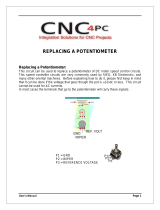
Using the Analog Input on the MDII
The ASPII/MDII has a built-in analog to digital converter. This input may be used in lieu of a digital pick-
up signal or to control Target speed, current program, or frequency generator output frequency. To use this
input with a potentiometer source, connect a pot wiper to Pin 6 of the serial interface port, high to the +5V
terminal, low to the Common terminal. The pot should have a resistance between 100 to 5000 ohms. Page
11 Items set destination source type and range for the analog input. Setting items 3 and 4 allows the pot
source range to be scaled between the min and max set points. A 0 to +5V signal may be used instead of
a potentiometer, connect signal to pin 7 of RJ45 and common to pin 6 of the RJ45 (P5-6). Item 2 on page
11 should be set for source type. FOR MORE information on using the analog input, see the following
4 pages (formerly “DAN-1a” Dart Application Note).
18

OVERVIEW
NOTE: This Applications Note Covers all controls in the MDII series with software revision numbers
of 2004 and above. To determine if this applies to your control, hold the
# button and apply power to the
unit. The MDII will cycle through a series of 3 numbers, then “--”. The second of these numbers is the
software revision (it will be 2xxx). The control will continue to cycle through the series of numbers until
you release the #
button, then it will enter normal operation.
The MDII series of controls features an analog input. This input, which uses 2 pins on the RJ45 “modular”
connector, can be used with a variety of signals. The signal from the analog input can be routed to one
of several points, to provide control or “feedback” information to the MDII. This applications note will
cover four major topics:
• What types of signal sources can be used
• How those signals can be used by the MDII
• Using the Field Customizing for this application
• How to hook up the analog input
TYPES of SIGNAL SOURCES
The analog input of the MDII has been designed to use basically three types of analog signal sources:
• Potentiometer (1KΩ to 10KΩ only)
• 0 to +5VDC Voltage Source (source impedance < 10KΩ)
• 4 to 20ma. Current Source (input impedance = 250Ω .1%)
NOTE: Signals should be postive-going only, and should be within the range of zero to +5 volts DC.
The selection of signal source type tells the MDII how to best use the analog information. How this
selection is done is covered under the topic “Field Customizing” later in this document. Be sure to select
the appropriate type of signal source, or the results will probably be less than optimal. Let’s explore why
this is true, by looking at the way the MDII treats the various signal source types.
Potentiometer Input:
Because noise is often a problem with potentiometer signals, and to keep the MDII from unnecessarily
updating information (such as “target speed”) just because the potentiometer jiggled a little bit, selection
of the “Potentiometer” type of input forces the MDII to behave as follows:
First, the analog input must change its value by a small amount before the MDII will “pay attention” to
it. Once this has happened, the MDII will “track” the analog input (but will not change anything) until
the analog input (potentiometer) stops changing for about 1 second. When this occurs, the MDII will
update itself (including non-volatile storage, if needed) according to the new value of the analog signal.
This behavior is quite pleasant for use with a potentiometer used to control, say, Target Speed, but is
totally inappropriate for use as a feedback signal, due to the “stickiness” of the current value.
NOTE: ONLY this source type will work with the Frequency Generator.
Voltage Source Input:
Selecting this source type will allow rapidly changing analog voltage signals to be “tracked” by the MDII.
It is primarily intended for use as a “feedback” signal, replacing the conventional “pickup” signal or
“leader” signal (for master/follower), although it is not restricted to this use. Values obtained in this way
are not stored in “non-volatile” memory, thus they will “go away” when power is shut off to the MDII.
This should not be a problem for most applications, since the value of the analog input is re-acquired when
power is restored. By the way, although this input is actually designed for zero to +5VDC signals, other
signal ranges (positive voltage only) such as zero to +10VDC can be accommodated by the use of an
external resistive “divider”.
19
/