Page is loading ...

Technical Note: TimeView® digital display clocks
Installing/troubleshooting Spectracom TimeView digital display
clocks (Models TV230, TV400, TV210W and TV400W)
www.spectracomcorp.com 1 | Display clock troubleshooting
Purpose: When Spectracom Model TimeView® digital display clocks are operating normally, all six digits will be
present, with the correct time displayed and no portion of the display will be flashing.
There are a few factors that can affect the normal operation of the display clocks. Depending on the
specific Model, these factors can cause the hours value to be incorrect, the seconds portion of the
display to flash every second, the main portions of the display (hours, minutes and seconds) to
sequence in a pattern or the digits to be erratic or dim/no longer displayed (causing a blank screen).
TABLE OF CONTENTS
Section 1: Install-Troubleshooting summary: Syncing a TimeView display clock to a NetClock’s
Remote RS-485 output port ........................................................................................................2
Section 1A: Configuring the TimeView display clock for either 12 or 24 hour display mode ......................4
Section 2: Configuring the NetClock’s Remote RS-485 output port to sync a TimeView display clock ......5
Section 3: Display clock is showing the incorrect hours value ....................................................................7
Section 4: Display clock has flashing seconds ............................................................................................10
Section 5: Display clock is sequencing through hours/minutes/seconds (or the seconds are flashing
even though the NetClock is synced, as verified in Section 4:) ................................................12
Section 6: Display clock has missing segments, erratic display or no display ...........................................19
Section 7: Spectracom Technical Support .................................................................................................22
Note regarding Spectracom SecureSync NTP servers: In addition to all Models of Spectracom NetClocks being
able to sync TimeView display clocks, the Spectracom SecureSync (when a Model 1204-04: RS-485
output Option Card is installed in a rear panel Option Bay) can also sync display clocks. For simplicity,
the SecureSync is referred to as “NetClock Model 9400 series” in this document.

www.spectracomcorp.com 2 | Display clock troubleshooting
Section 1: Install-Troubleshooting summary: Syncing a TimeView
display clock to a NetClock’s Remote RS-485 output port
In order for one or more TimeView display clocks to be able to sync to a NetClock (as indicated by the seconds’
portion of the display clock no longer flashing each second), and for the hours portion of the display clock(s) to
show the correct local time, a few conditions must be met:
Note: With the Models 8175 and 8177 TimeView display clocks, these clock will cycle between displaying
Hours only, Minutes only and then Seconds when they are getting no data from the NetClock They will only
have flashing seconds if the NetClock is not in sync.
1) The NetClock’s RS-485 Remote output port needs to be configured to output either Data Formats 0 or
1. If the NetClock is not configured to output either of these two formats, the seconds’ portion will
continue to be flashing each second
Refer to Section 2 to configure the Remote output, if it’s not yet been reconfigured from the
factory default settings.
Refer to Section 4: to troubleshoot, if the seconds are flashing each second (or if the display is
consistently scrolling between hours only, then minutes only and then seconds only).
2) The NetClock must be in Sync (as indicated by its front panel “Sync” or “Time Sync” LED being lit solid
green). If the NetClock is not in Sync, the seconds’ portion of the display will be flashing each second.
Refer to Section 4: to troubleshoot, if the seconds’ portion is flashing each second (the seconds
are momentarily blinking off each second).
3) The display clock(s) has to be correctly wired to the Remote RS-485 output port on the back of the
NetClock. If the display clock isn’t properly wired to the NetClock, the seconds’ portion will be flashing
each second (in the earlier Models 8175 and 8177 TimeView display clocks, the clocks will cycle
between displaying Hours only, Minutes only and then Seconds only if they aren’t properly connected
to the NetClock).
Refer to Section 4: to troubleshoot, if the seconds are flashing each second (or if the display is
consistently scrolling between hours only, then minutes only and then seconds only).
4) The NetClock’s RS-485 Remote output port needs to be configured to output either Data Formats 0 or
1. If the NetClock is not configured to output either of these two formats, the seconds’ portion will
continue to be flashing each second (in the earlier Models 8175 and 8177 TimeView display clocks, the
clock will cycle between displaying Hours only, Minutes only and then Seconds only).

www.spectracomcorp.com 3 | Display clock troubleshooting
Refer to Section 4: to troubleshoot, if the seconds are flashing each second (or if the display is
consistently scrolling between hours only, then minutes only and then seconds only).
5) In order for the display clock to show the correct local time, the NetClock’s Remote output needs to be
configured to output local time.
Refer to Section 3: to troubleshoot, if the hours’ portion is not displaying local time (it’s
displaying UTC time, instead).
6) If the hours are displayed in 24 hour mode (default) but 12 hour mode is desired (or vice-versa), refer
to Section 1A.

www.spectracomcorp.com 4 | Display clock troubleshooting
Section 1A: Configuring the TimeView display clock for either 12 or
24 hour display mode
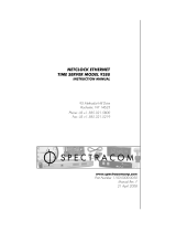
If the hours are displayed in 24 hour mode (default) but 12 hour mode is desired (or vice-versa) the
12/24 hour mode is configured in the TimeView display clock itself (this selection cannot be performed
in the NetClock).
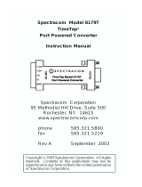
The 12/24 hour mode selection is not configurable via the NetClock’s Remote RS-485 output port. This
configuration is performed via the two push-button Mode and Set switches on the back of each
TimeView display clock. Refer to the label on the back of the clock and the TimeView instruction manual
for detailed information on configuring the display clock for either 12 or 24 hour display (see the
summary of this configuration below):
1's seconds
10's seconds
1's minutes
10's minutes
1's hours
10's hours
RF meter
Set
19
Mode
21
22
23
20
12/24 hour
brightness
exit data set
1001-1000-0706
Rev D
10
Mode
12
13
15
14
11
Set
1
100's group
3
4
6
5
2
10's group
1's group
100's sub-grp
1's sub-grp
10's sub-grp
17
18
Mode
8
9
buzzer
7
16
Mode
-
+
Power +12 VDC
Set
MODE SWITCH FUNCTION CHART
10's kHz
100's kHz
1's MHz
100's MHz
1's kHz
Set
10's MHz
Depress Mode switch one time each to scroll through selections
shown in chart above. Depress Set switch to scroll through
numbers indicated on face of clock. Refer to manual for a more
comprehensive description of "Mode" and "Set" switch functions.
RS-485
+
-
G
G
-
+
RS-485
This device complies with Part 15 of the FCC
Rules. Operation is subject to the following
two conditions: (1) This device may not cause
harmful interference, and (2) This device must
accept any interference received, including
interference that may cause undesired
operation.
1001-1000-0708 Rev B
#8-32 THREADED MOUNTING
HOLES FOR BULKHEAD
MOUNTING.
#8-32 THREADED MOUNTING
HOLES FOR BULKHEAD
MOUNTING.
MOUNTING SLOTS FOR
WALL MOUNTING
MODE 1 Pressing the Mode switch once initiates the display options parameters. Mode 1 enables 12 or
24-hour display format. Press the Set button to toggle between 12 hour and 24-hour display.
To return to the normal time display, consecutively press the Mode button to cycle though the rest of the
various modes (no need to press the Set button), or simply power cycle the display clock.
Mode and Set switches to toggle
between 12 and 24 hour modes

www.spectracomcorp.com 5 | Display clock troubleshooting
Section 2: Configuring the NetClock’s Remote RS-485 output port
to sync a TimeView display clock
The NetClock’s Remote RS-485 output port needs to be configured to output either Data Formats 0 or 1 in
order to sync TimeView display clocks. If it’s desired for the display clock(s) to show local time, configuration
for local time display is also configured in the NetClock (not in the TimeView display clock).
Notice: TimeView display clocks that are connected to the Remote port can’t sync to the NetClock until
the Remote RS-485 Port of the NetClock has been reconfigured from the factory default settings
to output Formats 0 or 1. By default, there is no data output until a Data Format has been
selected.
Note: Configuring the display clock to show the hours’ portion in either 12 or 24 hour mode is a
configuration of the display clock itself (using the Mode and Set push-button switches on the
back of each display clock to toggle between these two modes). This 12/24 hour mode selection
is not configurable via the NetClock’s Remote RS-485 output port. Refer to the display clock
manual and the label on the back of the display clock for information on toggling the display clock
between the 12 and 24 hour modes.
Configuring a NetClock Model 9483’s Remote port to output RS-485 data in Local time
For Signature Control, leave this as “output
always enabled”
For the Time Scale option, select “Local”
from the drop-down list
For the Local Clock option, select the desired
custom Local Clock (See the “Note” below)
Leave both of these two fields set to “None”
(See “Important Note” below).
For the First Format option, select
“Spectracom Format 0”

www.spectracomcorp.com 6 | Display clock troubleshooting
Note: Refer to Section 3: for information on creating a local clock, if one has not yet been created yet (only the
factory default values of “UTC”, “TAI” and “GPS” will be listed in the drop-down, if one hasn’t been
created yet).
Important Note: When syncing display clocks to the NetClock, the “First Format” field needs to be set to
either “Spectracom Format 0” or “Spectracom Format 1”. Make sure the “Second Format”
and “Third Format” fields are set to “None”. Selecting any other value in these two fields can
cause erratic operation of the display clock(s), including the seconds-portion of the display
clock not being lit.
After defining the Remote RS-485 output options, click “Submit”. A message stating “Configuration Successful”
should be displayed. TimeView display clocks already connected to the green 10 pin terminal block connector
on the rear panel should sync to the NetClock (the seconds portion of the display clock should stop flashing on
and off) within just a couple of seconds of pressing the Submit button.
4. Click “Submit”.

www.spectracomcorp.com 7 | Display clock troubleshooting
Section 3: Display clock is showing the incorrect hours value
Once the display clock has synchronized to a Spectracom NetClock via input RS-485 data, the seconds’ portion
of the display clock will no longer be flashing. The minutes and seconds values will also be correct. However,
depending on the current configuration of the NetClock’s RS-485 Remote port, the hour’s value may be ahead
(or behind) the current local time by several hours (unless the Remote port has been reconfigured for local
time, based on its default settings, the display clocks will show UTC time- not Local time).
The default settings for the NetClock’s RS-485 Remote output port is to output UTC time with no Time Zone
Offset or Daylight Saving Time correction applied (the provided RS-485 output is not local time by factory
default). In the US, depending on the Time Zone that you are located in, this displayed time may be ahead of
local time by 4 to 8 hours. In order for the display clock to show the correct local time (Such as Eastern,
Central, Mountain or Pacific) the Time Zone Offset and whether or not the NetClock should apply automatic
DST adjustment (as applicable for your location) needs to be configured in the NetClock’s Remote port that is
providing the RS-485 data to the TimeView display clock.
Refer to the applicable NetClock instruction manual for information on how to configure the Remote RS-485
output port to provide local time instead of UTC time. In Models 9300, 9200 and 9100 series NetClocks, this
will be accomplished by creating a “Local System Clock” and then referencing the assigned name of this local
clock in the “System Clock” drop-down in the appropriate Interface (or Interface Setup) -> Remote output port
configuration page of the NetClock’s web browser.
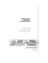
Figure 2 illustrates how to configure the Local System Clock in Model 9400 series NetClocks. In this example,
the Local Clock has been named “Eastern”. So, “Eastern” would be selected in the “Local Clock” drop-down in
the NetClock’s “SETUP” -> “OUTPUTS” -> “SLOT 3” page of the browser to output Eastern time to the display
clock(s) and other devices connected to the same RS-485 Remote port.

www.spectracomcorp.com 8 | Display clock troubleshooting
Figure 1: Configuration of the “Setup” / “Local Clock” page of the Model 9400 series NetClock’s web browser
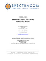
Figure 2 illustrates how to configure the Local System Clock in the NetClocks Model 9300 and 9200 series. In
this example, the Local Clock has been named “Eastern”. So, “Eastern” would be selected in the “System
Clock” drop-down in the NetClock’s Interface/Remote output page of the browser to output Eastern time to
the display clock(s) and other devices connected to the same Remote port.
Verify “Manually defined” and the
appropriate Time Zone has been
selected (i.e. “-05:00” for Eastern, “-
06:00” for Central, “-“-07:00” for
Mountain or “-08:00” for Pacific)
For states in the US that observe DST
change, verify “US-Canada” is
selected in the “Region” drop-down
field.

www.spectracomcorp.com 9 | Display clock troubleshooting
Figure 2: Configuration of the “System” / “Local System Clocks” page of the Model 9300 and 9200 series
NetClock’s web browser
Note: If an Ethernet Time Server, Model 9388, 9288 or 9188 is also connected to the same NetClock Remote
port as the display clock(s), Format 0 has to be the selected Data Format for that particular Remote
port. The Ethernet time servers can accept Data Formats 0 or 2, as configured in the Ethernet Time
Server. Changing the Remote port from Format 2 to 0 to sync a display clock will cause the Ethernet
Time Server(s) to lose sync if it’s configured to receive Format 2, instead of “0”. In this case the
Ethernet time server will need to be reconfigured to accept Format 0, and the Format 0 year value
stored in the time server will also need to be verified.
A better solution is if the NetClock has two Remote output ports, and the other port is available; connect the
Ethernet Time Server to one Remote port configured as Format 2 output and the TimeView display clock(s) on
the other port that is configured as Format 0 output.
Note: The NetClock Model 9400s have only one available RS-485 output port, so this port needs to be set to
Data Format 0 when syncing both display clocks and or more Ethernet time servers.
If the hour’s value was correct until shortly before or after a Daylight Saving Time change (such as in March or
November), the Remote port of the NetClock that is providing RS-485 data to the display clock may have its
DST rules incorrectly configured (causing the NetClock to adjust for DST at the incorrect time/date). On web-
based NetClocks, such as the Model 9100, 9200 and 9300 series, the DST configuration is in the “Local System
Clock” configuration. For more information on proper NetClock DST configuration, please refer to:
http://www.spectracomcorp.com/portals/0/support/pdf/DST_Rule_Change.pdf.
Verify the appropriate Time Zone has
been selected (i.e. “-05:00” for
Eastern, “-06:00” for Central, “-“-
07:00” for Mountain or “-08:00” for
Pacific)
For states in the US that observe DST
change, verify “Manually defined by
region” is selected with “USA (Post
2006)” selected in the drop-down.

www.spectracomcorp.com 10 | Display clock troubleshooting
Section 4: Display clock has flashing seconds
After the TimeView display clocks have been correctly connected to the NetClock’s Remote RS-485 port, and
as long as certain conditions have been met, the display clocks will synchronize to the Spectracom NetClock in
about 1 or 2 seconds (as indicted by a solid time display with the second’s portion of the display no longer
flashing). The flashing seconds is used as a remote indication that the display clock can’t sync to the NetClock,
or the NetClock is not synced to its external reference (GPS, IRIG, modem, etc).
Depending on the Model of the TimeView display clock, the potential conditions that can cause the flashing
seconds to occur vary slightly:
With the newer Models TV210W (9175) and TV400W (9177) digital display clocks (which started
shipping around April 2004), the flashing seconds are used as a remote indication that the display clock
can’t sync to the NetClock because either the NetClock is not synchronized (to its external reference)
or because the TimeView display is unable to either receive or understand the once-per-second RS-485
data stream from the NetClock’s Remote output port.
On the earlier Models TV230 (8175) and TV400 (8177) digital display clocks (which stopped shipping
around April 2004), the display clocks will only flash the seconds portion if the NetClock is not in Sync
with its external reference (if these displays clocks are not receiving RS-485 data from the NetClock,
they will instead sequence through the hours portion only, then the minutes portion only and then the
seconds portion only, as described in Section 3).
Note: If you are uncertain which Model TimeView display clock that you have, besides the Serial Number tag
located on the back of the display, the easiest way to identify the Model Number of the display clock is
both the Models TV230 (8175) and TV400 (8177) have a row of 10 DIP switches (in addition to the
Mode and Set switches) located on the back panel. The Model TV210W (9175) and TV400W (9177) do
not have any DIP switches located on the rear panel (they just have the Mode and Set switches
present).
The NetClock must be in sync for the display clock to sync
In order to prevent the second’s portion of the display from flashing, the NetClock (or Ethernet Time server)
that is providing RS-485 time data to the display clock must be synchronized to its external time reference (i.e.
GPS, IRIG, RS-485 data or modem). Verify that the NetClock’s front panel “Sync” or “Time Sync” light is green.
If it is not green, the NetClock is not in Sync with its primary reference and so the display clock won’t be able
to sync to the NetClock. (The times of both devices will match, but the seconds on the display clock will
continue to blink, as the display clock will still match the time if it is able to read the RS-485 time code data). If
the display is receiving time code data from an unsynchronized NetClock, a sync status character in the time
code data stream causes the seconds to flash on the display until the NetClock is back in sync with its
reference.

www.spectracomcorp.com 11 | Display clock troubleshooting
To troubleshoot a Spectracom WWVB-based NetClock/2 that has a red Time Sync light, please refer to:
http://www.spectracomcorp.com/portals/0/support/pdf/netclock2_reception.pdf
To troubleshoot a Spectracom GPS-based NetClock Models 9400, 9300, 9200 or 9100 series that does not
have a green “Sync”/ “Time Sync” LED, please refer to the GPS reception troubleshooting guide for the
applicable NetClock Model. These guides are located in the “Installation & Troubleshooting Guides” folder at:
http://www.spectracomcorp.com/Support/Library/ApplicationNotes/tabid/77/Default.aspx
With the Models TV210W and TV400W display clocks, if the NetClock has been verified as being synchronized
(the NetClock has a solid green front panel “Sync” or “Time Sync” LED) yet the seconds portion of the display
continues to flash every second, please refer to Section 3 for further troubleshooting assistance.

www.spectracomcorp.com 12 | Display clock troubleshooting
Section 5: Display clock is sequencing through
hours/minutes/seconds (or the seconds are flashing even though the
NetClock is synced, as verified in Section 4:)
Along as certain conditions have been met, the TimeView display clocks will synchronize to the Spectracom
NetClock in about 1 or 2 seconds (as indicted by a solid display and the second’s portion of the display no
longer flashing).
On the older Models TV230 (8175) and TV400 (8177) display clocks, the TimeView clock will continue
to sequence a display of hours portion only, then minutes portion only and then seconds portion only,
if the display clock is not receiving RS-485 data from the NetClock.
On the newer Models TV210W and TV400W, even if the NetClock is synchronized, the seconds will
continue to flash if the display clock is not receiving valid RS-485 data from the NetClock.
A few factors can prevent a TimeView display clock from being able to receive RS-485 data from the NetClock.
These include wiring/termination issues with the RS-485 bus or output Data Format configuration of the
NetClock’s RS-485 Remote output port.
All versions of the TimeView display clocks need to be connected via a twisted-pair cable to a Remote RS-485
output connector on the back of the NetClock. The cable between the NetClock and the display clock should
be pinned as “+Data” to “+Data”, “-Data” to “-Data” and “Ground” to “Ground”. On the back of the display
clock, the wires should be connected to the left-most three pins (the right three pins are a driver output from
the display clock). The wiring on this connector for the display clock (from left to right) is “+Data”, “-Data” and
“G”. Depending on the Model of the NetClock, this order may not be the same order as the pin-outs on the
Remote output of the NetClock. For example, on the NetClock Models 9483 and 8183, the output is in the
same order. But on the Models 9383, 9388 and 9389, the order of the pins is reversed, with it being “G”, “-
Data”, “+Data” instead (the two outer connectors are reversed). On NetClocks with the reverse configuration,
make sure to roll the two outside wires.
Back of the Model 9300
series NTP server (Use
either Port 1 or Port 2 on
a Model 9383 or a
Model 9389 with Option
02 installed)
Back of the TimeView display clock
Insert supplied 120 ohm
resistor into holes 1 and 2 of
this terminal block
connector
Insert supplied 120 ohm resistor
into holes 1 and 2 of this terminal
block connector

www.spectracomcorp.com 13 | Display clock troubleshooting
Figure 3: Model 9300 series NetClock’s Remote output port connected to one TimeView Display clock
Figure 4: Model 9400 series NetClock’s Remote output port connector to one TimeView Display clock
The wires inserted into the terminal blocks on the NetClock as well as the display clock(s) should be stripped of
insulation so bare wires are inserted into the terminal blocks.
The RS-485 bus, if connected to more than one device, the RS-485 wiring should be in a true-daisy chain
configuration with no branches to more than one device in the line. Branches in the RS-485 can cause
reflections that can result in flashing seconds. Make sure the only clock on the bus, or the last device on the
bus, is terminated into 120 ohms. For more information on RS-485 wiring and termination, please refer to the
RS-485 wiring primer located at:
http://www.spectracomcorp.com/portals/0/support/pdf/RS-485_wiring_primer.pdf.
This document provides additional information about using RS-485 wiring/termination and can help you
determine whether RS-485 is being sent to the display clock’s input. The following two figures below shows
how to properly connect more than one TimeView display clock to the NetClock.

www.spectracomcorp.com 14 | Display clock troubleshooting
Figure 5A: NetClock’s Remote port connected to two or more TimeView Display clocks
Back of the TimeView
display clock
Insert supplied 120 ohm
resistor into holes 1 and 2 of
this terminal block
connector
Insert supplied 120 ohm resistor into holes 1 and 2 of this
terminal block connector
Back of the TimeView
display clock
Back of the TimeView
display clock
Back of the TimeView
display clock
Back of the Model 9300
series NTP server (Use
either Port 1 or Port 2 on
a Model 9383 or a
Model 9389 with Option
02 installed)
Back of the Model 9300
series NTP server (Use
either Port 1 or Port 2 on
a Model 9383 or a
Model 9389 with Option
02 installed)

www.spectracomcorp.com 15 | Display clock troubleshooting
Figure 5B: NetClock’s Remote port connected to two or more TimeView Display clocks
Other abnormal conditions can also prevent the display clock from reading RS-485 data from the NetClock,
such as a bad Remote port on the NetClock, a hardware issue with the display clock, a broken wire on the
twisted-pair cable, etc. The wiring primer guide mentioned above contains a troubleshooting section which
may help. Also, the display clock may have been affected by a power glitch.
Try power cycling the display clock and see if the seconds stop blinking within a couple of seconds (the power
pack for input power may be located behind the clock, so the clock may need to be removed from the wall to
gain access to it). Some Models of the NetClocks provide two (redundant) side-by-side RS-485 output ports. If
both RS-485 outputs ports are present, the other RS-485 connector can also be used for validation testing.
Another method to test for a broken wire in the RS-485 bus is to temporarily connect the display clock to the
back of the NetClock with a short length of wire. If it syncs in this configuration, the display clock is working
and a wiring issue exists.
Verifying the presence of RS-485 data (at the NetClock’s RS-485 output and at the input to the back of the
display clock)
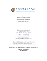
RS-485 data can be detected using either an oscilloscope or a multimeter.
A) Using an oscilloscope to detect RS-485 data
Due to the frequency response of a multimeter, RS-485 is a bit difficult to measure with this test equipment.
To easily identify whether RS-485 is present, use an oscilloscope or a service monitor to view the signal. The +
and œ Data should look similar to the Figure below. The + and œ Data lines are similar but just inverted from
Insert supplied 120 ohm
resistor into holes 1 and 2 of
this terminal block
connector
Insert supplied 120 ohm resistor into
holes 1 and 2 of this terminal block
connector
Insert supplied 120 ohm resistor into holes 1
and 2 of this terminal block connector

www.spectracomcorp.com 16 | Display clock troubleshooting
each other. The location of the signal compared to ground does not matter as RS-485 data is not based on
differences between data and ground.
Attenuated or distorted data indicates the Master Clock‘s Remote port output is bad or a device on the RS-485
is loading down the line. No data present indicates the RS-485 cable is broken or the NetClock’s RS-485
Remote RS-485 output data is not present. Check the NetClock’s RS-485 Remote output to see if the data is
present at this point. If it isn‘t, disconnect the bus and check the port again. If the data is present, a device is
loading down the bus. Disconnect each device one at a time until the bad device is located.
If the data isn‘t present, either the NetClock’s RS-485 output is bad, or with a Model 9400 series NetClock, its
RS-485 output port may not have been configured to output Data Format 0 or 1 yet (by factory default, the
NetClock Model 9400 series NetClocks output no RS-485 data, until they have been configured to output a
specified Data Format)/
FIGURE 5: RS-485 data viewed with an oscilloscope
B) Using a multimeter to detect RS-485 data
Note: The photos shown further below depict checking the RS-485 Remote port on a NetClock Model 9300
series NTP server. For a Model 9400 series NTP server, the RS-485 terminal block pins to check are the
two left-most pins on the 10 pin rear panel terminal block connector (as shown directly below):
An oscilloscope is the best test device to ensure RS-485 is present into the back of the display clock. However,
if one is not available, a multimeter can also be used as a quick-test. To look for RS-485 data on the “+Data”
and “-Data” lines, set the meter to measure DC voltage.
Pin 1
+ Data
Pin 2
- Data
Pin 3
Ground

www.spectracomcorp.com 17 | Display clock troubleshooting
Starting at the NetClock’s Remote output port (with the RS-485 cable disconnected), place the black probe on
the round (“G”) pin and the red probe on the “+Data” pin. This DC voltage should be around 2 vdc (if the line
is terminated into 120 ohm load) with a distinctive “heartbeat” drop in voltage every second (the DC voltage
will be around 4vdc unloaded). Due to the frequency response of the meter, the DC voltage will momentarily
drop by about 0.1vdc each second (as shown below).
Then move the red probe over to the “-Data” pin. This voltage should be around 0.4 to 0.5 vdc with a
distinctive “heartbeat” drop in voltage (by about 0.1 vdc) every second (the DC voltage will be around 0.7 vdc
unloaded).
If the DC levels on both pins are the same, or if both do not drop in voltage at all, the output port is likely bad.
Some NetClocks have two Remote ports. If a second Remote port is present (such as with the Models 9383 or
9283), it can be used as a side-by-side comparison to ensure the test is working properly. The +Data and –
Data signals on both ports should be similar.
Enlarged view

www.spectracomcorp.com 18 | Display clock troubleshooting
Checking for RS-485 data at the RS-485 input on the back of the display clock
If the RS-485 signals appear to be present on the NetClock’s Remote output port, perform this same check on
the terminal block input on the back of the first (or only) display clock in the RS-485 bus that isn’t syncing. If
the data is not present on this terminal block but is present on the cable, a cable issue likely exists. If the data
is present on both of the input pins on the back of the display clock, try power cycling the display. If the clock
still doesn’t sync within just a couple of seconds, a likely hardware issue with the display clock. Contact Tech
Support for an RMA number to be assigned. Refer to Tech Support.
Enlarged view
Back of the TimeView display clock
Note: The RS-485 input wires should be
located in Pins 1, 2 and 3. Verify:
“+Data” is present on “Pin 1”
“–Data” is present on Pin 2
(Ground is Pin 3)

www.spectracomcorp.com 19 | Display clock troubleshooting
Section 6: Display clock has missing segments, erratic display or
no display
An erratic, blank or dim display indicates either a NetClock Model 9400 series RS-485 Remote output
configuration exists (not applicable to earlier series NetClocks) or a hardware issue exists, likely related to
input DC power (loss or a problem with the RS-485 input from the NetClock is not likely to affect the display
clock segments from showing a “normal” time with seconds counting up). This condition can be due to a
problem with the TimeView display itself, or it may also indicate a problem with the power pack (wall adapter)
that is used to power the TimeView display clock. To resolve the issue, it is necessary to determine whether
the issue is a configuration issue with the NetClock Model 9400 series, an issue with the display clock or a
problem with the external power pack.
(Applicable to NetClock Model 9400 series NTP servers only): First, if the display clock(s) are connected to a
NetClock Model 9400 series NetClock for synchronization, verify the RS-485 Remote port of the NTP server is
configured to output only one Data Format. A newer feature added in NetClock Model 9400 series was the
ability to output more than one Data Format in the same second (back-to-back output Data Format strings).
Configuring the RS-485 Remote output to send more than one Data Format can cause erratic operation of the
TimeView display clocks (such as the seconds’ digits not being displayed, for example).
To verify the RS-485 Remote output is configured to output only one Data Format (either Data Format 0 or 1),
open the NTP server’s web browser and navigate to the Setup -> Outputs -> Slot 3 (ASCII RS-485 and Relays)
page of the browser. In the default “ASCII RS-485 tab”, verify the “First Format” Field is set to either
“Spectracom Format 0” or “Spectracom Format 1”. Next, make sure the “Second Format” and “Third Format”
fields are set to “None”. If not, reconfigure these fields as stated and then press Submit. The display clock
should not show a normal time 6 digit time display.
(Applicable to all NetClocks)
If there is more than one display clock located at the site, try swapping the power pack with another one from
a same Model display clock that is operating normally. If the display clock is still erratic, still dim or digits still
aren’t being displayed with a different power pack, the issue is likely with the display clock. If the symptoms
follow the power pack, the power pack is the likely cause of the symptoms.
An analog or digital multimeter can be used to measure the output voltage of the power pack to help
determine if the power pack is the cause of the blank display: The different TimeView Models use different
power packs. Refer to the appropriate section below for your particular Model:
Models TV210W (9175) and TV400W (9177) display clocks:
The power packs (Spectracom P/Ns PS03-0T0J-WM01 for the Model TV210 power pack or PS06-0E0J-DTA0 for
the TV400W power pack) state that the output voltage is +12vdc with this voltage being present, whether the

www.spectracomcorp.com 20 | Display clock troubleshooting
power pack is loaded or unloaded. Disconnect the power connector from the back of the display clock. With
the power pack still connected to AC power, measure the DC voltage on the power pack connector (The center
pin is positive and the outer shell is negative). The measured voltage should be about 12vc. If the voltage is
less than about 12vdc, the power pack cannot drive the display clock, so the power pack needs to be replaced.
Important Note: Connecting a non-Spectracom supplied, unregulated 12vdc output power pack to the
Models TV21W and TV400W will likely cause damage to ICs inside the display clock,
due to a potential over-voltage condition (the power pack must have a regulated
12vdc output). Damage incurred while using a non-Spectracom supplied,
unregulated output power supply is not covered under warranty.
Model TV400 (8177) display clock:
The power pack (Spectracom P/N T00058) states the voltage is +12vdc output, but this is only with a load on
the power pack (unloaded voltage is around 18vdc). The power pack should be measured under the load of
the display clock, but can be checked with it disconnected from the clock. If you have a multimeter with sharp
ends on the leads, pierce the insulation and measure the DC voltage. It should be around + or -12 vdc
(depending on which lead you put in which wire). If you measure less than around 12 vdc, the power pack is
bad and needs to be replaced. If the multimeter has dull ends on the leads, disconnect the power connector
from the clock and measure the DC voltage on the power pack connector (center pin is negative and outer
shell is positive). The voltage needs to be at least 15vdc. If the voltage is less than about 15vdc, the power
pack cannot drive the display clock, so it needs to be replaced.
Model TV230 (8175) display clock:
The power pack that was provided with the Model 8175 (P/N T00054) had a 16.5VAC output to the display
clock. Set the multimeter to measure AC voltage in order to check the output of this power pack. It should
measure about 16.5VAC.
The 16.5VAC power packs are no longer available from Spectracom. However, the Model TV230 can also
operate on a DC input as desired. The specific input DC level will determine the brightness of the digits. The
minimum input DC voltage is about 15vdc and the maximum should not exceed about 20vdc.
Results of the voltage check:
A) Power pack has the correct output voltage present
If the power pack is outputting a sufficient voltage as tested above, there is an internal issue with the
display clock and it will need to be returned for service. Contact Spectracom Technical Support with
the Model and Serial Number for an RMA Number to be assigned. Refer to Tech Support.
B) Power pack has either a low or no output voltage present
If the power pack’s output voltage is low or not present, the power pack is unable to power the display
clock. The power packs are covered under a two year warranty. If the display clock is less than two
/