Software s Power Supply PC Monitor Operating instructions

Type
Operating instructions
1
Power Supply PC Monitor
Software Instruction
Install Driver
1. Decompress software package “Power Supply PC Monitor V X.X.X” to the
following files.
2. Select the serial chip driver, as shown below:
3. Double-click or right-click to decompress the serial port Chip Driver package
and install the CH340 driver
4. Click Install, wait for the installation to complete, click OK, as shown below:
2
5. Go back to the computer and click device Manager to check the COM
number and driver, as shown below :
Software Operation
Double-click the right mouse button to open the “exe” file, save the other files
The initialization screen is displayed, as shown in the following figure.
3
How to connect
1. Click “comm Setting” from left-top Menu bar, the serial port parameter setting
screen is displayed.
2. Set serial port parameters to set a port number, click the drop-down list, and
select a COM number corresponding to the COM number of “USB-SERIAL
CH340”. Other parameters are the default values.
4
3. Click "Open" to complete the control connection of the upper computer.
5
Interface Guide
Channel Status Area
Parameter setting: Enter the required parameters in the parameter editing box
and press Enter to complete the parameter setting.
Voltage/Current waveform Area
When the channel is open, the Voltage/Current curve of the channel can be
observed in the waveform area.
6
Coordinate
Click the “Coordinate setting in the voltage/Current waveform display area to
jump out of the setting interface and select the adaptive mode or manually enter
the numerical mode.
Adaption mode
Click " " next to electric pressure shaft adaptive and current adaptive, and the
state is " ". Click "OK" to realize the adaptive mode.
Manually enter a numerical mode
Enter the desired coordinates and click” OK” to confirm the input.
7
List waveform editing Area
1. Click in the upper left corner or directly click “edit” in the List
waveform editing area. Input the required voltage, current, time, and Y/N
after the serial number in the table (unchangeable) (when set to Y, the
data is normally output; when set to N, the data is not output). The number
of data groups can be set to 1-100
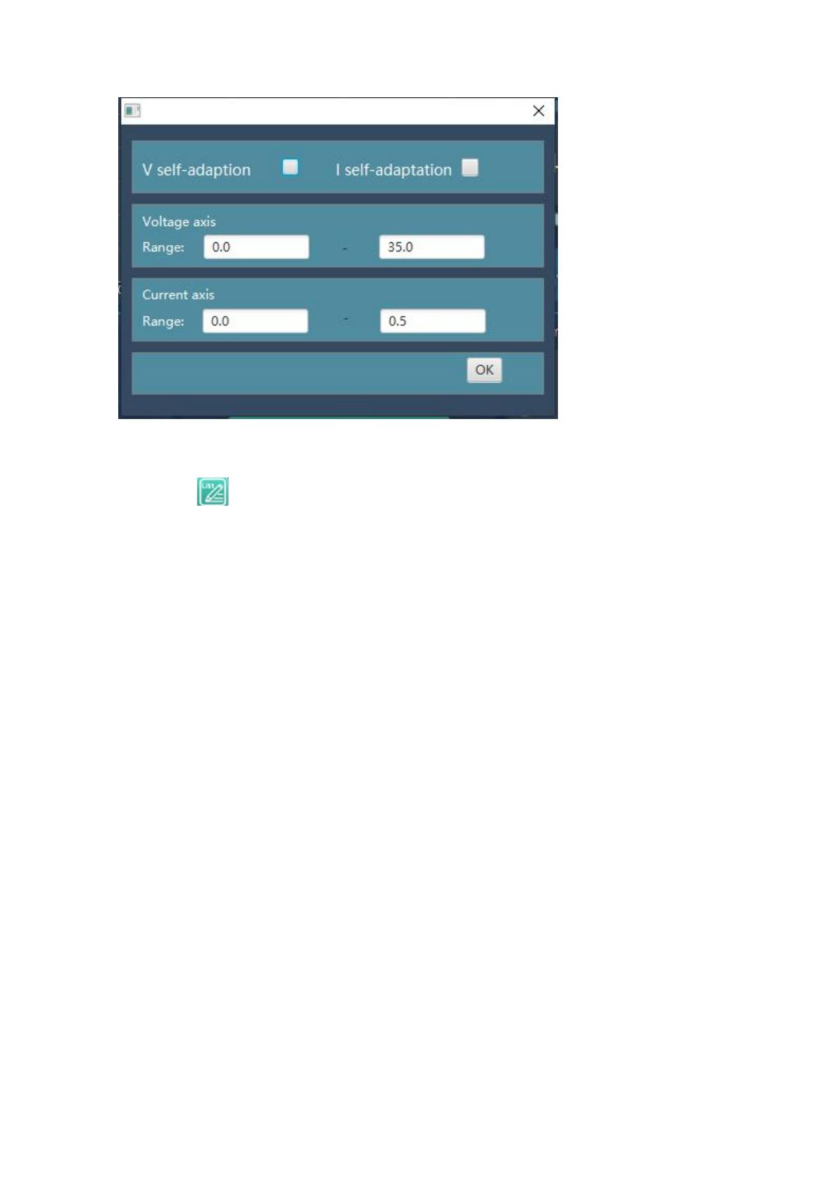
2. Parameter setting: Enter the required parameters in the parameter editing
box and press Enter” to complete the parameter setting.
3. Set the start group number, end group number, and period for data output
in sequence. Click “Start” to output data in sequence.
4. Click “Stop” to stop data output.
8
Quick Set Area
We can set 8 groups of common values (M1-M8) by ourselves, which is
convenient for subsequent direct calls.
Set the parameter
Let's take setting the M1 parameter as an example
Click after M1 to make it the selected state . In U/I/OVP/OCP, input the
required voltage/current/output overvoltage/output overcurrent values, and so on,
up to 8 groups of values can be input.
Call the numerical
Let's take setting the M1 parameter as an example
9
Click after M1 to make it the selected state , Click the “Call” in the upper
right corner of the quick setting area to quickly deliver the four parameters
U/I/OVP/OCP to the power supply.
V1.0
  • Page 1 1
  • Page 2 2
  • Page 3 3
  • Page 4 4
  • Page 5 5
  • Page 6 6
  • Page 7 7
  • Page 8 8
  • Page 9 9

Software s Power Supply PC Monitor Operating instructions

Type
Operating instructions

Ask a question and I''ll find the answer in the document

Finding information in a document is now easier with AI