Somfy GDO77 User manual

Type
User manual

Somfy GDO77 is an electric button designed for controlling garage doors, offering enhanced safety and convenience. It features a compact design that fits discreetly in your garage, and allows for easy installation with clear instructions provided. The GDO77 ensures the integrity of safety circuits, preventing any damage during operation.

Somfy GDO77 is an electric button designed for controlling garage doors, offering enhanced safety and convenience. It features a compact design that fits discreetly in your garage, and allows for easy installation with clear instructions provided. The GDO77 ensures the integrity of safety circuits, preventing any damage during operation.

1MK3001RP April 2023 R1
This equipment must be installed and used in accordance with
these instructions. Failure to follow these instructions could result
in damage to the integrity of the safety circuits.
Two persons are required to install this product to ensure safe
handling procedures.
CAUTION
Do not wear rings, watches or loose clothing while installing or
servicing the unit and ensure correct PPE is worn.
To avoid serious personal injury from entanglement, remove any
loose objects from the equipment prior to operating door.
DANGER
Installation and wiring must be in accordance with your local
building and electrical regulations.
Any electrical work must be carried out by a suitably qualified
person, if in doubt consult a qualified electrician.
Use only the mains lead supplied with the Remote Control Unit as
failure to do so will invalidate the warranty.
Connect the mains lead to an adjacent 13 amp 3 pin switched
socket. The plug must be fitted with a 13 amp fuse.
Note: For optimum electrical safety this unit should be connected
to circuit protected by a R.C.D. (max 30 mA trip rating).
This unit should not be installed in a damp or wet space or on a
damp or single skinned wall without sufficient spacers.
DANGER
Disconnect electric power to the control unit before making repairs
or removing covers.
Install the Control Box and/or Switch Control in a location where
the garage door is visible, but out of the reach of children. The
door must be in direct sight of the control and must not be
operated via security or doorbell cameras. Do not allow children to
operate push button(s) or remote control(s). Serious personal injury
from a closing garage door may result from misuse of the operator.
CAUTION
Activate unit only when the door is in full view, free of obstructions
and operator is properly adjusted. No one should enter or leave the
garage while the door is in motion. Do not allow children to play
near the door.
Please read these instructions carefully prior to commencing the installation of the door.
IMPORTANT SAFETY RULES
Always check on delivery that the order details are correct and the
door is undamaged, especially before removing any existing doors.
Sequence of Installation & Contents
01. Pre-Installation and Component Check
02. Installation Options
03. Prepare the Guide Rails
04. Installation of Box Supports
05. Fix Guide Rails
06. Install the Axle Assembly
07. Fit Emergency Overrides
08. Install the Curtain in the Guides (incl curtain adjustment)
09. Attach the Curtain
10. Set-up the Control Unit (where supplied)
11. Set the Motor Limits
12. Commissioning
13. Technical Assistance
14. Notes
GDO77 - Electric Button
Installation Instructions
01. PRE-INSTALLATION AND COMPONENT CHECK
2MK3001RP April 2023 R1
Check:
i. Delivery note
ii. Order sheet
iii. Door dimensions / colour
iv. Opening dimensions / clearances
v. Components
vi. Check for any damage to the guide rails
or the outside roll of the curtain
Do not proceed further with the
installation unless you are sure that
the door is the correct size, and all
components are present.
WIDTHS
Manufacturing Width = Over Guide Width
Drive Through Width = Over Guide Width less
150mm for 75mm guides
HEIGHTS
Manufacturing Height = Guide Height
Total Height = Guide Height + End Plate
Headroom/End Plate up to 2.5m Guide Height =
300mm
Drive Through Height = Guide Height less 100mm
Before removing the old door check that the door size and colour
correspond with that which was ordered.
Structural condition of opening.
i. Ensure the area around the opening is strong enough to
support the weight of the door.
ii. The surface where the door is to be fitted must be flush and
reasonably smooth. Small irregularities in the brickwork will be
acceptable.
iii. No obstacles in fitting footprint eg. no sharp objects, pipes,
cables, bumps etc. sticking out from the pillars, lintel or header
to twist the guides, distort the fascia or catch on the curtain.
iv. The lintel must not protrude backwards or forwards from the
brick piers. Should the lintel protrude backwards or forwards
from the brick piers this will require special instructions, please
consult your supplier.
v. The floor must be flat/level. If necessary install a sub-frame to
ensure secure, flush and level fixing (recommended minimum
70 X 70 PAR). The lintel must not protrude backwards or
forwards from the brick piers. Should the lintel protrude
backwards or forwards from the brick piers this will require
special instructions, please consult your installer.
Fitting Notes
vi. It is recommended that 2 people are available for fitting all
door sizes.
vii. The door must be fitted square and level, irrespective
of the shape of the opening; on no account should any
compensation be made to suit an irregular opening.
viii. Ensure all necessary tools are to hand before starting.
ix. The door package and its contents should be checked for
obvious damage before removal of the wrapping.
IF THERE IS ANY DAMAGE YOUR SUPPLIER SHOULD BE
CONTACTED IMMEDIATELY.
x. Ensure there is a suitable 13amp 3 pin switched socket
adjacent to where the Remote Control Box is to be fitted.
xi. Ensure all tools and door components are gathered together
inside the garage prior to starting the installation.
Recommended Tools for Assembly:
2 stepladders
Spirit/laser level
Tape measure
Power drill
10mm A/F spanner
Slot screwdriver
Pozidrive screwdriver
3.5mm drill bit
7.0mm drill bit
11.0mm drill bit
3mm A/F Allen key
4mm A/F Allen key
Hacksaw
Suitable wall plugs (not supplied)
Suitable fixings (not supplied)
Note: In case of power failure a manual override system is fitted as standard but this can only be operated from inside the garage. If
the garage has no service entrance door then an exterior release kit must be fitted to allow manual operation of the garage door from
outside.
01. PRE-INSTALLATION AND COMPONENT CHECK (CONTINUED)
PRE-INSTALLATION CHECK
3MK3001RP April 2023 R1
01. Control Unit (where supplied) *
02. Motor (fitted into axle)
03. 70mm Octagonal Axle
04. 2 to 6 Pairs of Rings for Auto Lock Collars (fitted on axle)
05. Safety Brake
06. R/H End Plate
07. 2 to 6 Autolock Straps (3 elements) *
08. 2 to 6 No.8 x 1/2” Pozi Pan Screws *
09. L/H End Plate
10. Guide Rails (UPH 75) 75mm or (UPH 250) 90mm
fitted with Brush Insert
11. Curtain
12. End Locks (fitted to curtain)
13. Bottom Slat (fitted to curtain)
14. Rubber Seal (fitted to bottom slat)
15. Override Eye *
16. 6 No. M8 X 21mm Penny Washers *
17. 10 No. 4mm X 8mm Rivets * (for securing endlocks)
18. Crank Handle Clip *
19. Crank Handle *
20. Optional Half Box
21. Optional Full Box Cover
22. Optional Box Supports
*Supplied in Accessory Box
Recommended Fixings (not supplied)
12 x 1” Self Tapping Screws for Steel
12 x 2 1⁄2” Countersunk Screws for
Masonry and Wood
Guides, axle assembly and the crank handle will be
wrapped together in one bubble wrapped parcel
and strapped together. The curtain is individually
packed. A separate accessories box is packed with
the installation and end user instructions, the
attachment/locking arms, the accessory pack and
a box containing the electrical items.
A A
B B
C C
D D
E E
F F
8
8
7
7
6
6
5
5
4
4
3
3
2
2
1
1
1
2
3
4
4
4
5
6
7
7
7
8
8
8
9
10
10
11
11
13
12
14
Internal Face Fit Reveal Fit
Combination of Face and Reveal Fit
Fitted to existing or New Timber Frame
Undersize Face Fit
Set Back Face Fit
19
15
18
16
17
COMPONENT CHECK
02. INSTALLATION OPTIONS
20
21
22
4MK3001RP April 2023 R1
If the guides require cutting down refer to the ‘Widths and
Heights’ information on page 2. If face fixing where possible set
the guide height at least 110mm above the structural opening
height to maximise drive through height.
If you need to reduce the length of the guide rails you must cut
from the bottom of the guide rails.
i. Position guides
ii. Drill a minimum of 4 guide fixing holes, with a 7mm pilot hole
and 13mm outer hole. Position the first hole position 250mm
from the top of the guide and the second hole 250mm from
the bottom of the guide. Equally space out the remaining
holes with a maximum gap of 500mm between each fixing.
Avoid mortar joints and edges of bricks etc.
REVEAL
DRILL
OR FACE DRILL
GUIDE/ DOOR
HEIGHT
BOTTOM SLAT HANG
DOW N 110 m m
DRIVE THROUGH
HEIGHT Note: Guides are handed. Please take note of the orientation of
the guides. If cutting guides cut excess length from bottom of
guide.
REVEAL FIX
INTERNAL SIDE
13mm 7mm
FACE FIX
INTERNAL SIDE 13mm
7mm
Where supplied, the box supports need to be riveted to the fascia to hold them in place.
03. PREPARE THE GUIDE RAILS
04. INSTALLATION OF BOX SUPPORTS – OPTIONAL EXTRA FOR HALF BOX OR FULL BOX
i. First fix the fascia in place then position the box supports
within the fascia with equal distances between each support
(see Drawing A).
ii. Drill a hole with a 4.2mm drill bit through each box support
and the fascia.
iii. Fasten the box support to the fascia using a 4 x 8 rivet.
Note: Ensure that both ends of each box support are positioned
within the lip of the fascia (see Drawing B).
A A
B B
C C
D D
E E
F F
8
8
7
7
6
6
5
5
4
4
3
3
2
2
1
1
A
A A
B B
C C
D D
E E
F F
8
8
7
7
6
6
5
5
4
4
3
3
2
2
1
1
B
Correct box support
positioning
5MK3001RP April 2023 R1
Note: Before positioning check that there are no sharp objects or
bumps sticking out from the pillars, lintel or header to twist the
guides or that will catch the door during operation.
If in doubt pack the guides and end plates out by at least 10mm.
i. Slot end plate lugs into guides (see Drawing A) remembering
the guides are handed
ii. Position guides and end plates against opening
iii. Hold or prop securely the assembly in position
iv. Drill fixing holes (min 4 in guides and 2 in each end plate) -
see 4.ii
v. Fix guides/end plates with minimum No. 12 x 21⁄2”
countersunk screws (and plugs) to masonry/timber or 12 x 1
self tapping screws to steel.
Note: If end plates are fitted within the reveal, the side of the end
plates must be fitted to the structure with at least 2 fixing points.
Ensure that fixing heads are clear of the curtain operation to
prevent damage when the door is in use.
Note: Extreme care should be taken while manoeuvring the
door into place to avoid the possibility of snapping the end
plate lugs. It is imperative that fixings are put through the end
plates into the wall as the aluminium lugs are not designed to
carry the weight of the door.
A
Lug
Note: Axle assembly
must be level
Check:
Back faces of guides and end plates are flush and untwisted
(see Drawing B)
Guides are vertical/parallel/same height
B
Dummy End
i. For doors supplied with a dummy end only, fix the bracket
(A) to the end plate using the screws provided in the
accessories kit.
Ensure that the open end of the bracket cup is facing
towards the top of the end plate (B).
ii. Locate the dummy end in to the bracket fitted to the end
plate (B).
If the dummy end appears to be too short, loosen the grub screw
and extend the dummy end to the required length, then tighten
the grub screw.
iii. Fold the top tabs on the bracket round the bearing to secure
the bearing.
iv. Insert the motor end of the axle into the opposite end plate.
Dummy End Bracket
A
B
05. FIX GUIDE RAILS
06. INSTALL THE AXLE ASSEMBLY
6MK3001RP April 2023 R1
Anti-Fall Back Device
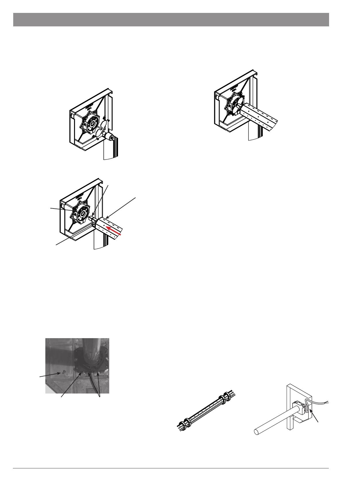
Note: The rivet securing the dummy end into the axle is use for
transport purposes only and MUST be removed before installing
the axle.
i. Remove the retaining plate from the pre-built end plate (see
Drawing A). If retaining plate is not on the endplate, check
your accessories box.
ii. Loosen the safety collar on the dummy end shaft and extend
the shaft fully into the safety brake (see Drawing B).
iii. Attach the motor side of the axle to the opposite end plate.
iv. Re-install the retaining plate over the safety brake and onto
the end plate (see Drawing C). Ensure the retaining plate sits
inside the shaft groove to prevent movement.
v. Fix the reaining plate securely to the end plate using the pre-
existing fixings supplied or spare fixings from the accessories
kit.
vi. Slide the safety collar tight up to the dummy end and tighten.
i. Fasten the motor end of the axle, using the bracket supplied,
to the other end plate using the screws provided and the
prepared tapped holes in the end plate.
ii. Ensure that the motor limits are facing down and that the
override hole is towards the chamfered front end of the
end plate.
iii. Ensure that the collars are the correct way around
(see Drawing C).
iv. Ensure the motor power lead is securely fastened to the end
plate and away from the curtain. – (see Drawing D).
v. You must ensure that you allow for a drip loop in the motor
cable to prevent water from running down the cable and into
the motor. Cable ties can be attached to the motor cable
to act as drip loop to prevent water entering the motor.
D
Screw &
Washer
Override Exit Motor Limits C
Fix the Motor End of the Axle
Drip Loop
06. INSTALL THE AXLE ASSEMBLY (CONTINUED)
IMPORTANT INFORMATION: In the event that the door fails and the safety brake is triggered to prevent the door from falling, the safety
brake MUST BE REPLACED with a like-for-like brake. This includes activation of the interlock switch OR turning of the inner dial.
A
Detail 1:
Remove retaining plate from pre-build endplate.
If retaining plate is not on the endplate, check your
accessories box.
C
Detail 2:
Slide axle into safety brake. Attach motor side to
the endplate.
D
Detail 3:
Install retaining plate back over the safety brake
and onto the endplate as shown. Ensure plate sits
inside of shaft grove to prevent movement. Use
pre-existing fixings that was supplied on the endplate
or fixings can be found inside of fixing kit
E
Detail 4:
Push fixing clip upto axle as close as possible. Screw clip to axle
to prevent shaft movement.
WEIGHT:3.89
A3
SHEET 1 OF 1
SCALE: 1:20
STATUS:
REVISION:
MATERIAL:
DATE
FINISH:
UNLESS OTHERWISE SPECIFIED:
(ALL DIMENSIONS ARE IN 'mm'
)
TOLERANCES:-
LINEAR:
ANGULAR:
APPV'D
CHK'D
DRAWN
CONFIDENTIAL. COPYRIGHT
© OF SECURITY WINDOWS AND SHUTTERS UK LTD (SWS UK LTD).
THE REPRODUCTION OR TRANSMISSION OF ALL OR PART OF THIS DOCUMENT, WHETHER BY
PHOTOCOPYING OR STORING IN ANY MEDIUM BY ELECTONIC MEANS OR OTHERWISE,
WITHOUT THE WRITTEN PERMISSION OF SWS UK LTD, IS PROHIBITED.
ALL SUPPLIERS OR COMPONENTS, ARTICLES, MIXTURES OR SUBSTANCES TO SWS UK LTD, OR ANY
AFFILIATE OF SWS UK LTD, MUST BE FULLY COMPLIANT WITH EU REGULATION (EC) NO. 1907/2006
(REACH) AND ALL APPLICABLE RELATED LEGISLATION.
NAME
Stock Code:
TITLE:
PROJECT:
Retaining plate installation
N/A
Part/Assy locale: C:\PDM\Library\Assembly File\
Drawing locale: C:\Users\thomasb\Security Window Shutters Limited\Development - Engineering\Engineering\03 - Projects\01 - Current\P161 - Allugaurd\03 - Documents\04 - General Documents\Marketing Material\CAD Files\Fitting Instructions\
AB
BA
B
C
D
E
G
H
J
K
L
N
R
S
T
U
V
W
X
Y
Z
AC
AD
AE AG
AH
AJ
AK
AL
AP
AR
AU
AV
AW
AX
AY
AZ
BC
BD
BF
BG
BH
BJ
BK
BL
BM
BN
BP
BR
BT
BU
BV
BW
BX
BZ
A
A A
B B
C C
D D
E E
F F
8
8
7
7
6
6
5
5
4
4
3
3
2
2
1
1
Notes:
N/A
SeceuroGlide Alluguard 77
Assembly
CN
ZONE
DESCRIPTION
APPROVED
DATE
REV
MD No.:
DO NOT SCALE DRAWING
mm
deg
A
Safety Brake
Shaft
Dummy End
Safety Collar
or Jubilee Clip
depending on
configuration
B
A
Detail 1:
Remove retaining plate from pre-build endplate.
If retaining plate is not on the endplate, check your
accessories box.
C
Detail 2:
Slide axle into safety brake. Attach motor side to
the endplate.
D
Detail 3:
Install retaining plate back over the safety brake
and onto the endplate as shown. Ensure plate sits
inside of shaft grove to prevent movement. Use
pre-existing fixings that was supplied on the endplate
or fixings can be found inside of fixing kit
E
Detail 4:
Push fixing clip upto axle as close as possible. Screw clip to axle
to prevent shaft movement.
WEIGHT:3.89
A3
SHEET 1 OF 1
SCALE: 1:20
STATUS:
REVISION:
MATERIAL:
DATE
FINISH:
UNLESS OTHERWISE SPECIFIED:
(ALL DIMENSIONS ARE IN 'mm'
)
TOLERANCES:-
LINEAR:
ANGULAR:
APPV'D
CHK'D
DRAWN
CONFIDENTIAL. COPYRIGHT
© OF SECURITY WINDOWS AND SHUTTERS UK LTD (SWS UK LTD).
THE REPRODUCTION OR TRANSMISSION OF ALL OR PART OF THIS DOCUMENT, WHETHER BY
PHOTOCOPYING OR STORING IN ANY MEDIUM BY ELECTONIC MEANS OR OTHERWISE,
WITHOUT THE WRITTEN PERMISSION OF SWS UK LTD, IS PROHIBITED.
ALL SUPPLIERS OR COMPONENTS, ARTICLES, MIXTURES OR SUBSTANCES TO SWS UK LTD, OR ANY
AFFILIATE OF SWS UK LTD, MUST BE FULLY COMPLIANT WITH EU REGULATION (EC) NO. 1907/2006
(REACH) AND ALL APPLICABLE RELATED LEGISLATION.
NAME
Stock Code:
TITLE:
PROJECT:
Retaining plate installation
N/A
Part/Assy locale: C:\PDM\Library\Assembly File\
Drawing locale: C:\Users\thomasb\Security Window Shutters Limited\Development - Engineering\Engineering\03 - Projects\01 - Current\P161 - Allugaurd\03 - Documents\04 - General Documents\Marketing Material\CAD Files\Fitting Instructions\
AB
BA
B
C
D
E
G
H
J
K
L
N
R
S
T
U
V
W
X
Y
Z
AC
AD
AE AG
AH
AJ
AK
AL
AP
AR
AU
AV
AW
AX
AY
AZ
BC
BD
BF
BG
BH
BJ
BK
BL
BM
BN
BP
BR
BT
BU
BV
BW
BX
BZ
A
A A
B B
C C
D D
E E
F F
8
8
7
7
6
6
5
5
4
4
3
3
2
2
1
1
Notes:
N/A
SeceuroGlide Alluguard 77
Assembly
CN
ZONE
DESCRIPTION
APPROVED
DATE
REV
MD No.:
DO NOT SCALE DRAWING
mm
deg
A
Detail 1:
Remove retaining plate from pre-build endplate.
If retaining plate is not on the endplate, check your
accessories box.
C
Detail 2:
Slide axle into safety brake. Attach motor side to
the endplate.
D
Detail 3:
Install retaining plate back over the safety brake
and onto the endplate as shown. Ensure plate sits
inside of shaft grove to prevent movement. Use
pre-existing fixings that was supplied on the endplate
or fixings can be found inside of fixing kit
E
Detail 4:
Push fixing clip upto axle as close as possible. Screw clip to axle
to prevent shaft movement.
WEIGHT:3.89
A3
SHEET 1 OF 1
SCALE: 1:20
STATUS:
REVISION:
MATERIAL:
DATE
FINISH:
UNLESS OTHERWISE SPECIFIED:
(ALL DIMENSIONS ARE IN 'mm'
)
TOLERANCES:-
LINEAR:
ANGULAR:
APPV'D
CHK'D
DRAWN
CONFIDENTIAL. COPYRIGHT
© OF SECURITY WINDOWS AND SHUTTERS UK LTD (SWS UK LTD).
THE REPRODUCTION OR TRANSMISSION OF ALL OR PART OF THIS DOCUMENT, WHETHER BY
PHOTOCOPYING OR STORING IN ANY MEDIUM BY ELECTONIC MEANS OR OTHERWISE,
WITHOUT THE WRITTEN PERMISSION OF SWS UK LTD, IS PROHIBITED.
ALL SUPPLIERS OR COMPONENTS, ARTICLES, MIXTURES OR SUBSTANCES TO SWS UK LTD, OR ANY
AFFILIATE OF SWS UK LTD, MUST BE FULLY COMPLIANT WITH EU REGULATION (EC) NO. 1907/2006
(REACH) AND ALL APPLICABLE RELATED LEGISLATION.
NAME
Stock Code:
TITLE:
PROJECT:
Retaining plate installation
N/A
Part/Assy locale: C:\PDM\Library\Assembly File\
Drawing locale: C:\Users\thomasb\Security Window Shutters Limited\Development - Engineering\Engineering\03 - Projects\01 - Current\P161 - Allugaurd\03 - Documents\04 - General Documents\Marketing Material\CAD Files\Fitting Instructions\
AB
BA
B
C
D
E
G
H
J
K
L
N
R
S
T
U
V
W
X
Y
Z
AC
AD
AE AG
AH
AJ
AK
AL
AP
AR
AU
AV
AW
AX
AY
AZ
BC
BD
BF
BG
BH
BJ
BK
BL
BM
BN
BP
BR
BT
BU
BV
BW
BX
BZ
A
A A
B B
C C
D D
E E
F F
8
8
7
7
6
6
5
5
4
4
3
3
2
2
1
1
Notes:
N/A
SeceuroGlide Alluguard 77
Assembly
CN
ZONE
DESCRIPTION
APPROVED
DATE
REV
MD No.:
DO NOT SCALE DRAWING
mm
deg
C
7MK3001RP April 2023 R1
i. Check there are at least 2 pairs of autolock collars on the axle. They should all be fitted
onto the axle in the same position (see Drawing A). One collar from the pair will have
restricted movement due to fixing in the axle, this will be the positioning of the straps.
1
Left Hand viewed
from centre of door
2
Right Hand viewed
from centre of door
Screw
Upper Collar
Lower Collar
The motor limits are accessible from two sides. This enables the motor to always be fitted to the end plate so that limits are facing down
and so that the override is towards the front of the end plate.
i. Drill hole for override eye through end plate flange
ii. Remove the screw and the upper collar
iii. Insert override eye in hole in motor adjacent to limit adjusters
iv. Locate and tighten the upper and lower collars around the motor
v. Insert and tighten the holding screw and washer from above
vi. Hook crank handle in eye
vii. Secure clear of shutter with crank handle clip
On a left hand door the motor cable will
exit the motor vertically down.
On a right hand door the motor cable
will exit the motor vertically up. You
must ensure that you include a drip
loop to prevent water from entering
the motor.
This will ensure that you do not have
to cut down the roller plate to enable
the override eye to be fitted.
Possible Override Exit Options
A
Override Exit
07. FIT EMERGENCY OVERRIDES
08. INSTALL THE CURTAIN IN THE GUIDES
AlluDrive override eye
8MK3001RP April 2023 R1
SAFETY NOTE: A minimum two people are required for this
procedure to ensure safe handling.
ii. Carefully unwrap and remove the outer bubble wrap
protection and place over the axle to stop damage to inside
of curtain during installation.
iii. Using minimum 2 people, carefully lift the curtain assembly
up level with the axle. Practice has shown that it is best to
place one hand on the axle, keeping that arm straight, and
support the curtain roll on that shoulder (see Drawing B).
iv. Feed the bottom lath over the top of the axle and down
between the guide rails taking care not to scuff the curtain
assembly. Proceed until half of the curtain has been fed over
the axle.
v. Carefully unroll the remaining curtain until it is balanced over
the axle (see Drawing C).
vi. Slide the autolock straps onto the top slat, ensuring they are
equally spaced with more than 800mm between each one.
vii. With 1 person positioned at the top of the door and one
person positioned at the bottom, carefully feed the curtain
into the guide until the curtain is reaches the floor.
Note: Do not let the curtain ‘free fall’ over the axle as this
will result in damage to the curtain and/or the safety edge
transmitter.
WEIGHT:32.11
A3
SHEET 1 OF 1
SCALE: 1:20
STATUS:
REVISION:
MATERIAL:
DATE
FINISH:
UNLESS OTHERWISE SPECIFIED:
(ALL DIMENSIONS ARE IN 'mm'
)
TOLERANCES:-
LINEAR:
ANGULAR:
APPV'D
CHK'D
DRAWN
CONFIDENTIAL. COPYRIGHT
© OF SECURITY WINDOWS AND SHUTTERS UK LTD (SWS UK LTD).
THE REPRODUCTION OR TRANSMISSION OF ALL OR PART OF THIS DOCUMENT, WHETHER BY
PHOTOCOPYING OR STORING IN ANY MEDIUM BY ELECTONIC MEANS OR OTHERWISE,
WITHOUT THE WRITTEN PERMISSION OF SWS UK LTD, IS PROHIBITED.
ALL SUPPLIERS OR COMPONENTS, ARTICLES, MIXTURES OR SUBSTANCES TO SWS UK LTD, OR ANY
AFFILIATE OF SWS UK LTD, MUST BE FULLY COMPLIANT WITH EU REGULATION (EC) NO. 1907/2006
(REACH) AND ALL APPLICABLE RELATED LEGISLATION.
NAME
Stock Code:
TITLE:
PROJECT:
SWS3308
N/A
Part/Assy locale: C:\PDM\Library\Assembly File\
Drawing locale: C:\Users\thomasb\Security Window Shutters Limited\Development - Engineering\Engineering\03 - Projects\01 - Current\P161 - Allugaurd\03 - Documents\04 - General Documents\Marketing Material\CAD Files\Fitting Instructions\
AB
BA
B
C
D
E
G
H
J
K
L
N
R
S
T
U
V
W
X
Y
Z
AC
AD
AE AG
AH
AJ
AK
AL
AP
AR
AU
AV
AW
AX
AY
AZ
BC
BD
BF
BG
BH
BJ
BK
BL
BM
BN
BP
BR
BT
BU
BV
BW
BX
BZ
A
A A
B B
C C
D D
E E
F F
8
8
7
7
6
6
5
5
4
4
3
3
2
2
1
1
Notes:
N/A
LT Assembly
CN
ZONE
DESCRIPTION
APPROVED
DATE
REV
MD No.:
DO NOT SCALE DRAWING
mm
deg
C
B
Note: The door is manufactured with the curtain height to suit the length of
guide supplied. The door will not lock down properly if the curtain is either too
tall or too short. If the guide height has been adjusted on site, check that the top
of the curtain is between ½ to 1½ slats above the top of the guide (see Drawings
D). If the curtain is too tall, remove slat(s) following the steps below. If too short
notify the supplier.
Curtain Adjustment (also used for repairs)
i. To remove slat(s), first remove the curtain from the guides by carefully raising the
curtain until half of the curtain has been fed over the axle. Carefully balance the
curtain on the axle.
ii. Remove the attachment straps.
iii. Carefully remove the staples from the end lock and remove the end lock (see
Drawing E) before sliding out the slat (see Drawing F). Preferably remove slats
from the top of the curtain to save having to remove and refit the bottom slat.
D
½ - 1½
slats
iii. If replacing damaged slats as part of a repair,
slide in the new slat(s).
iv. Re-secure the endlock(s) with 2 No. 4mm x
8mm rivets supplied (see Drawing G).
v. Re-install the curtain by repeating steps ii to
vii above.
E
F
G
08. INSTALL THE CURTAIN IN THE GUIDES (CONTINUED)
9MK3001RP April 2023 R1
i. Use the motor override or a test lead to rotate the axle until
the locking joint attachment holes are positioned as shown in
Drawing A.
Note: One collar from each pair will pre-fixed into the axle, this
will be the positioning of the straps.
ii. Attach the autolock strap pins into each of the collars on the
axle, ensuring they are pushed up to the collar that is fixed into
the axle.
Note: You must ensure the strap pins are fully engaged into the
collars on the axle before fixing the second collar in place to
prevent the product failing (see Drawing B).
iii. Slide the loose collars to engage the other end of the strap
pins and use the No.8 x 1/2” pozi pan screws supplied to fix the
loose collars to the axle (see Drawing C).
Note: It is recommended to drill 4mm pilot holes before fixing
the screws. Take care not to damage the motor inside the axle.
iv. Use the motor override or a test lead to raise the door slightly.
Check that the semi-circular curtain attachment strap coils up
flush with the collars (see Drawing D).
B
C
A
D
Control unit set up instructions are provided in the control panel accessory box along with
the control unit and you can also access them digitally using this QR code or link:
www.alluguard.co.uk/downloads
09. ATTACH THE CURTAIN
10. SET-UP THE CONTROL UNIT (WHERE SUPPLIED)
10 MK3001RP April 2023 R1
Closed/Down Limit Setting
i. Carefully close the door using either a motor test lead or the
control unit so that the curtain is fully down and the top slat is
pushed forward.
ii. Use the limit adjusting tool to adjust the down limit of the
door until the motor stops in the correct position.
Turn the down limit in the ‘+ direction to increase the
travel of the door.
Turn the down limit in the ‘– direction to reduce the
travel of the door.
Open/Up Limit Setting
iii. Carefully open the door using either a motor test lead or the
control unit so that the curtain is fully open.
iv. Use the limit adjusting tool to adjust the up limit of the door
until the motor stops in the correct position.
Turn the up limit in the ‘+ direction to increase the travel
of the door.
Turn the up limit in the ‘– direction to reduce the travel of
the door.
Note: Do not use a drill to adjust the limits.
Override Exit
Which limit is up and which limit is down?
The up and down limit is determined
using the direction arrows next to the limit
adjusters and the direction of axle rotation
to either close or open the door.
Limit Adjusting Tool (green)
Direction of Axle Rotation
+ Increase the travel in this direction
– Reduce the travel in this direction
Limit Adjuster
Both the up and down limits require setting.
Note: Incorrect setting of the limits risks damage to the motor,
curtain and attachment devices.
Important: When the door is fully closed, the autolock strap should be
positioned with a slight bend which locks the collar out (see Drawings A, B & C).
A
C
B
Check the Limit Positions
Run the motor in both directions until the limit switches cut out the motor travel.
Carry out any fine adjustments. One turn of the adjustment screw corresponds to
approximately 70° turn of the axle.
In order that the locking joints operate effectively, the position of the shaft in the closed
position needs to be finely adjusted.
Do not adjust past this position as this will impose excessive loads on the mechanism.
This motor is fitted with a thermal trip; this stops the motor from overheating.
Be aware that excessive running of the door may cause the thermal trip to operate, if this
happens; please wait 20 minutes before trying to operate the door again.
A A
B B
C C
D D
E E
F F
8
8
7
7
6
6
5
5
4
4
3
3
2
2
1
1
ALLUDRIVE MOTOR
10. SET THE MOTOR LIMITS
11MK3001RP April 2023 R1
Checking the Direction of Rotation of the Motor
i. Press simultaneously on the ^ and v buttons until
the motors up and down movement occurs to
enter motor adjustment mode.
Indicator light 1 flashes slowly.
ii. Press button ^ or v to check the motors direction
of rotation.
If the motors direction of rotation is correct,
move on to step iii.
If the direction of rotation is is incorrect, press
the stop button until the motors up and down
movement occurs, check the motors direction
of rotation again and move on to step iii of the
motor end limit setting procedure.
iii. If the motor end limits are already set, move on to step
viii to exit motor adjustment mode.
If the motor end limits are not set, check that the motor
is released: the two push-buttons should
be pressed.
Note: The motor end limits can also be set with a setting
tool. In this case, set the motor end limits with the cable
then move on to step viii to exit motor adjustment mode.
iv. Press ^ button to position the garage door in the upper
position.
Adjust the upper position with buttons ^ and v.
v. Press the motors upper end limit push-button.
vi. Press v button to position the garage door in the lower
position.
Adjust the low position with buttons ^ and v.
vii. Press the motors low end limit push-button.
viii. Press simultaneously on the ^ and v buttons or press the
(prog) button until the motors up and down movement
occurs to exit motor adjustment mode.
Indicator light 1 goes out.
Final Checks
i. Remove any protective plastic coverings.
ii. Wipe curtain & guides with damp cloth.
iii. Touch-up any small scratches.
iv. Check all electrical & operating equipment is installed
and functioning correctly (especially the safety edge) and
complete UKCA marking label and paperwork.
v. Check direction handle needs winding to open door and fit
appropriate label supplied to crank handle.
N.B. Check the front of the curtain to make sure that it is not
rubbing on the lintel.
The manual override will not function after the door is operated
by remote control, until the power to the motor has ‘timed out’.
This will take a few moments to occur.
If you wish to demonstrate the manual override immediately after
opening the door press either the stop button on the handset or
simulate a power cut by switching off the power to the Control Unit.
Upon completion it is your responsibility to train the customer
how to operate the door correctly and safely and provide them
with the operating and maintenance instructions supplied.
If you require any on site technical assistance including repair or maintenance
queries please call 01524 772400 or email [email protected]o.uk.
Control unit set up instructions are provided in the accessory box and you can
also access them digitally using this QR code or link:
www.alluguard.co.uk/downloads
SOMFY MOTOR
12. COMMISSIONING
13. TECHNICAL ASSISTANCE
12 MK3001RP April 2023 R1
14. NOTES
  • Page 1 1
  • Page 2 2
  • Page 3 3
  • Page 4 4
  • Page 5 5
  • Page 6 6
  • Page 7 7
  • Page 8 8
  • Page 9 9
  • Page 10 10
  • Page 11 11
  • Page 12 12

Somfy GDO77 User manual

Type
User manual

Somfy GDO77 is an electric button designed for controlling garage doors, offering enhanced safety and convenience. It features a compact design that fits discreetly in your garage, and allows for easy installation with clear instructions provided. The GDO77 ensures the integrity of safety circuits, preventing any damage during operation.

Ask a question and I''ll find the answer in the document

Finding information in a document is now easier with AI