Page is loading ...

400A AC/DC CLAMP METER
AUTO RANGING
PART NO:
TTICM600V
(..151478)
OPERATING
INSTRUCTIONS

2600V CLAMP METER
CONTENTS
INTRODUCTION .........................................................................................................3
• Intended Use ......................................................................................................................3
• Product Contents .............................................................................................................3
GENERAL SAFETY ......................................................................................................4
SAFETY INSTRUCTIONS ............................................................................................4
• Electrical Symbols .............................................................................................................5
GENERAL SPECIFICATIONS ......................................................................................6
EXTERNAL OVERVIEW ..............................................................................................6
• Function Selector Overview ............................................................................................7
• LCD Screen Overview .......................................................................................................8
• Buttons Overview .............................................................................................................8
OPERATING INSTRUCTIONS ....................................................................................9
• AC/DC Current Measurement .........................................................................................9
• AC/DC Voltage and Voltage Frequency (% Duty Cycle) Measurement ...................10
• Continuity Test / Resistance / Diode / Capacitance Measurement .........................11
• Non-Contact (NCV) AC Electric Field Sensing .............................................................12
• Other Functions ................................................................................................................. 13
TECHNICAL INDEX .....................................................................................................14
• Accuracy Specications ...................................................................................................14
• DC Current Measurement ................................................................................................14
• AC Current Measurement ................................................................................................14
• DC Voltage Measurement ................................................................................................14
• AC Voltage/Voltage Frequency ......................................................................................15
• Resistance Measurement ................................................................................................15
• Continuity/Diode Measurement ....................................................................................16
• Capacitance Measurement .............................................................................................16
• Duty Ratio Measurement ................................................................................................16
• Frequency Measurement.................................................................................................17
• Non-Contact AC Voltage Detecting (NCV) ...................................................................17
MAINTENANCE ...........................................................................................................18
• General Maintenance .......................................................................................................18
• Battery Replacement ........................................................................................................ 18
WARRANTY INFORMATION .....................................................................................20

3OPERATING MANUAL
INTRODUCTION
TTICM600V is a true RMS (4000 count) auto ranging digital clamp meter.
This meter measures AC/DC Current, AC/DC Voltage, Resistance, Capacitance, Diode Test,
Continuity and Non Contact Voltage detection.
The instruction manual includes relevant safety information and warning indication, please
read them carefully and strictly observes all warnings and notes.
INTENDED USE
The clamp meter is to be used only for electrical inspection within the specications the
machine is rated for. Failure to use the machine within the specications may result in serious
injury or death.
PRODUCT CONTENTS
CAUTION
!The supplied test leads are used for MAINS measurements CATll 1000V,
CATlll 600V according to IEC 61010-031
Unpack and take out the clamp meter, please check carefully if the following attachments are
complete or intact.
1. Operating instruction manual
2. Pair Test Leads
3. TTTICM600V Clamp Meter

4600V CLAMP METER
GENERAL SAFETY
Prior to using clamp meter, please read the product manual and ensure you have a solid
understanding of the meter’s functions and features.
CAUTION
!Upon rst use of the machine, ensure the test leads aren’t damaged and
in good working order.
WARNING
!
The warnings, cautions, and instructions discussed in this instruction
manual cannot cover all possible conditions or situations that could
occur. It must be understood by the operator that common sense and
caution are factors that cannot be built into this product, this must be
supplied by the operator.
SAFETY INSTRUCTIONS
Please note the “warning signs and words”. Warning means the condition or action that may
cause threat to user or damage to the instrument or equipment to be measured.
The clamp meter is designed according to EN61010-1, 61010-2 and electromagnetic radiation
protection EN61326-1 safety standards, CATII 600V, CATIII 300V and pollution grade II.
If the meter is not used properly as per the instructions, the protection provided may be
weakened or lost.
Anyone using this instrument should be knowledgeable and trained about the risks involved
with measuring voltage, especially in an industrial setting, and the importance of taking safety
precautions and of testing the instrument before and after using it to ensure that it is in good
working condition.
This product has been tested to the requirements of IEC 61010
CAT II: Applicable to test and measuring circuits connected directly to utilization points
(socket outlets and similar points) of the low-voltage MAINS installation.
CAT Ill: Applicable to test and measuring circuits connected to the distribution part of the
building’s low-voltage MAINS installation.
•Check the clamp meter and test leads before using, guard against any damage.
If any abnormalities or damage are found, do not use the clamp meter.
•Examine the test leads for damaged insulation or exposed metal.
Check test lead continuity. Replace damaged test leads before using the Meter.
•Do not use the clamp meter without having rear cap and battery cover in place, otherwise
electric shock may occur.
•To avoid false readings that can lead to electrical shock and injury, replace the batteries as
soon as the low battery indicator appears.
•When using the test leads, keep ngers behind the nger guards on the probes.
Do not contact the bare wire and connector, unused input terminal or the circuit being
measured when clamp meter is in operation.
•Connect the common test lead before connecting the live test lead.
When disconnecting test leads, disconnect the live test lead rst.
•Function selector shall be set at the correct position prior to measurement.
Do not change selector settings while measuring to guard against damage to the meter.

5OPERATING MANUAL
•Refrain from applying voltage over DC1000V/AC750V between the clamp meter terminals
and ground to guard against electric shock and clamp meter damage.
•Be careful in measuring RMS voltage higher than DC or AC 30V, such voltage poses a shock
hazard.
•Do not measure current in circuits carrying more than 600A with the meter jaw.
•Do not measure voltage or current higher than the allowable input value.
•Disconnect circuit power and discharge all high-voltage capacitors before you measure
resistance, continuity, or capacitance.
•Do not modify the internal wiring in the meter to guard against damage to the meter and
danger.
•Do not store or use clamp meter in an explosive or ammable environment, high
temperature, high humidity or strong electromagnetic eld.
•Comply with local and national safety regulations and requirements. Use personal
protective equipment such as approved rubber gloves, face protection, and ame-
resistant clothing to prevent shock and arc blast injury where hazardous live conductors
are exposed.
•Clean the clamp meter case with soft cloth and neutral detergent. To prevent causing
corrosion to the case, or damage to the instrument do not use abrasives or solvents.
Make sure all water is removed before use.
ELECTRICAL SYMBOLS
Double insulation Diode measurement
Grounding AC or DC (alternating current or direct current)
Warning High voltage hazard
AC (alternating current) Continuity measurement
DC (direct current) This symbol signies product complies with
Australian requirements
Capacitance

6600V CLAMP METER
GENERAL SPECIFICATIONS
•Display count: 4000
•Polarity display: Auto
•Maximum jaw opening: 28 mm
•Power supply: 2 x AAA 1.5V batteries
•Dimension: 215mm x 63mm x3mm
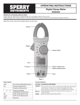
EXTERNAL OVERVIEW
1.
2.
4.
6.
3.
7.
10.
9.
5.
8.
1. NCV sensor
2. Clamp jaws
3. Hand guard
4. LED indicator
5. Jaw opening trigger
6. Function selector
7. LCD display
8. Function buttons
9. Terminal input jack (red and positive +)
10. COM input jack (black and negative -)

7OPERATING MANUAL
FUNCTION SELECTOR OVERVIEW
POSITION DESCRIPTION
VDC voltage measurement
VAC voltage measurement
AAC current measurement
ADC current measurement
NCV Non-contact voltage measurement
Hz% Frequency/ duty radio measurement
Diode measurement
Continuity measurement
ΩResistance measurement
Capacitance measurement
OFF Shut-down

8600V CLAMP METER
LCD SCREEN OVERVIEW
SYMBOL DESCRIPTION
Caution AC/DC voltage is higher
than 30V
Data hold
Negative reading
AC/DC AC/DC measurement
Low battery indicator
Diode measurement
Continuity measurement
Relative value measurement
Ω, k Ω, M Ω Resistance unit
mV, V Voltage unit
μA, mA, A Current unit
nF, μF, mF Capacitance unit
Hz% Frequency unit, duty radio
βTransistor amplication factor
NCV Non-contact voltage measurement
LED LED measurement
Auto power o
BUTTONS OVERVIEW
BUTTON DESCRIPTION
SELECT
In composite scale, press this button to switch between the corresponding functions
or ranges.
REL/ZERO
Press this button to store the current reading as a reference for future readings. When
the LCD display value is reset to zero, the stores reading will be subtracted from the
future readings. Press this button again to exit the relative value mode.
MAX/MIN
Short press of this button will enter the maximum/minimum measurement mode and
long press will exit the function. *Valid for ACV/DCV, ACA/DCA,°C/°F, resistance and
capacitance scales*
HOLD/
A short press of this button will enter or exit the data hold mode; a long press
(about 2s) will turn the LCD backlight on or o
DC
AC
AUTO MAXMIN ZERO
MkΩ Hz%nmFVA˚C˚F
NCV
H

9OPERATING MANUAL
OPERATING INSTRUCTIONS
AC/DC CURRENT MEASUREMENT
1. Select the corresponding current range.
2. Press the trigger to open the clamp jaws, and fully enclose one conductor.
3. Only one conductor can be measured at a time, or the measurement reading will
be wrong.
NOTE:
•Do not insert the testing leads during current measurement to avoid electric shock.
•The current measurement must be taken with safeguard protection.
•Press the REL button to return to zero before the DC current measurement, and
meanwhile the centre hole of the jaw should be perpendicular to the current direction to
ensure accuracy.
•The open circuit zeroing reading may be relatively large after (high) DC current
measurement. Please perform the AC current detection again to counteract the
remanence signal by alternating electric eld.
SELECT
SELECT
REL/ZERO
MAX/MIN HOLD/
True RMS
AC/DC CLAMP METER
AC/DC CLAMP METER
NCV
400A
40A
V
V
Hz%
Hz
OFF
Ω
V
Hz
COM
CAT III 300V
CAT III 600V
Ω
REL/ZERO
MAX/MIN HOLD/
True RMS
NCV
400A
40A
V
V
Hz%
Hz
OFF
Ω
V
Hz
COM
CAT III 300V
CAT III 600V
Ω
AUTO
Hz
AUTO
Hz

10 600V CLAMP METER
AC/DC VOLTAGE AND VOLTAGE FREQUENCY (% DUTY CYCLE)
MEASUREMENT
1. Select the corresponding function V (AC) or V (DC)
2. Insert the red test lead into the positive (+) jack, and the black into the COM jack.
3. Connect test leads to the measured circuit.
NOTE:
•Do not input voltage above 600V to prevent electric shock or damage.
The input impedance of each range scale is 10MΩ, this load eect in high resistance
measurement may cause error. If the input impedance is lower the than 10kΩ, the error
can be ignored (<0.1%).
•Be cautious to avoid electric shock when measuring high voltage.
•Please check the functions by applying a known voltage before use.
SELECT
REL/ZERO
MAX/MIN HOLD/
True RMS
AC/DC CLAMP METER
NCV
400A
40A
V
V
Hz%
Hz
OFF
Ω
V
Hz
COM
CAT III 300V
CAT III 600V
Ω
V
Hz
V

11OPERATING MANUAL
CONTINUITY TEST / RESISTANCE / DIODE / CAPACITANCE
MEASUREMENT
1. Select the corresponding function scale Ω
2. Insert the red test lead into the positive (+) jack, and the black into the COM jack.
3. Connect test leads to the measured circuit.
NOTE:
•Don’t input voltage above DC 60V or AC 30V to avoid personal injury.
•Disconnect all the other parts of the circuit to avoid inaccuracy.
•Before measuring resistance, disconnect all power and fully discharge all capacitors to
avoid injury or device damage.
•If the resistance is over 0.5Ω when the test leads are short-circuited check the test leads for
looseness or other abnormalities.
•If the measured resistor is open or the resistance exceeds the maximum range, the LCD will
display “OL”.
•It is recommended to use “REL” measurement mode for capacitance less than 100nF.
SELECT
REL/ZERO
MAX/MIN HOLD/
True RMS
AC/DC CLAMP METER
NCV
400A
40A
V
V
Hz%
Hz
OFF
Ω
V
Hz
COM
CAT III 300V
CAT III 600V
Ω
Capacitance
Continuity
Diode
Resistance

12 600V CLAMP METER
NON-CONTACT (NCV) AC ELECTRIC FIELD SENSING
The electric eld sensing sensitivity is divided into two levels (“EFHI” and “EFLo”).
The meter defaults to “EFHI”/ Users can select dierent sensitivity levels according to the
intensity of the measured electric eld.
1. Select NCV on the function selector. Display will show “EFHI”.
2. Hold sensing end close to a charged electric eld (socket, insulated wire, etc.).
The LCD will display “-“ with beeps and a red LED ashing.
3. As the intensity of the measured electric eld increases, more segments (----) display, the
buzzer beeps quicker and LED ashes faster.
4. If the electric eld is around 110 V AC 50Hz/60Hz, press the Select button to enter “EFLo”
mode.
NOTE:
•When using this function, in order to avoid the COM input interference, which will aect
the electric eld and the accuracy, please pull the black test lead out of the COM input.
•Keep your hand away from the meter jaw as it can interfere with the reading.
SELECT
REL/ZERO
MAX/MIN HOLD/
True RMS
AC/DC CLAMP METER
NCV
400A
40A
V
V
Hz%
Hz
OFF
Ω
V
Hz
COM
CAT III 300V
CAT III 600V
Ω

13OPERATING MANUAL
OTHER FUNCTIONS
•Auto power o: The meter will automatically power o to save batteries if there is no
operation within 15 minutes. You can wake it up by pressing any button or restart it after
turning the switch o.
Disabling Auto power o: Press and hold the SELECT button in the o state and turn on
the meter again to disable the auto power o function. Restart the meter after shutting it
down to resume the function.
•Low battery detection: The battery voltage will be automatically detected as long as the
meter is on. If it is lower than 2.6V, the LCD will display the “ ” symbol.
•Low battery shut down function: When the battery voltage is lower than 2.5V, the LCD
displays the “ ” symbol, the “Lo.bt” interface appears and last for about 10 seconds, the
buzzer will sound 3 consecutive beeps, the meter will now enter an automatic shutdown.

14 600V CLAMP METER
TECHNICAL INDEX
ACCURACY SPECIFICATIONS
•Accuracy: ± (% reading + counts) – the calibration period is 1 year.
•Ambient temperature and humidity: 23°C±5°C: <80%RH.
•Temperature coecient: the accuracy assured temperature condition is 18°C-28°C, the
range of ambient temperature uctuation is stable within ±1°C.
When the temperature is less than 18°C or over 28°C, the additional temperature
coecient error is 0.1 x (specied accuracy)/°C.
DC CURRENT MEASUREMENT
RANGE RESOLUTION ACCURACY
40A 0.01 A
±(2%+5)
400A 0.1A
AC CURRENT MEASUREMENT
RANGE RESOLUTION ACCURACY
40A 0.01 A
±(2%+5)
400A 0.1A
CAUTION
•When the measured current reaches the warning value, there will be an alarm sound.
•With DC current DCA mode, the LCD may display non-zero value in open circuit state, users
can press “REL” button to clear display to zero before each measurement.
DC VOLTAGE MEASUREMENT
RANGE RESOLUTION ACCURACY
400mV 0.1mV ± (0.7%+3)
4V 0.001V
± (0. 5%+2)
40V 0.01V
400V 0.1V
600V 1V

15OPERATING MANUAL
AC VOLTAGE/VOLTAGE FREQUENCY
RANGE RESOLUTION ACCURACY
4V 0.001V ± (1. 0% +5 )
40V 0.01V
± (0 8%+5)
400V 0.1V
600V 1V
VOLTAGE FREQUENCY 0.01Hz-0.01kHz ± (0.5 +2)
CAUTION
•Short press SELECT in AC voltage/Hz scale to enter the Hz function.
•The input impedance is about 10MΩ.
•Current/voltage frequency response: 45Hz~400Hz, displays true RMS value.
•AC crest factor of non-sinusoidal wave can reach 3.0 at 4000 counts while it can only reach
1.8 at 6000 counts . The additional error should be added for the corresponding crest
factor as follows:
a. Add 3% when the peak factor is 1~2
b. Add 5% when the peak factor is 2~2.5
c. Add 7% when the peak factor is 2.5~3
RESISTANCE MEASUREMENT
RANGE RESOLUTION ACCURACY OVERLOAD PROTECTION
400Ω 0.1Ω ± (1.0%+2)
600Vrms
4kΩ 0. 001KΩ
± (0. 8%+2)40kΩ 0.01KΩ
400kΩ 0.1KΩ
4MΩ 0. 001MΩ
± (2. 5%+ 5)
40MΩ 001MΩ
CAUTION
•Measured resistance value = displayed value – resistance value of short-circuited test leads
•Open circuit voltage is about 1V

16 600V CLAMP METER
CONTINUITY/DIODE MEASUREMENT
FUNCTION RANGE RESOLUTION ACCURACY
400Ω/600Ω 0. 1Ω
• <10Ω : Consecutive beeps
• >31Ω: No beep
• The median: uncertain
4V/6V 0.001V
• The open circuit voltage is about 4V .
• For the silicon PN junction diode, the
voltage value is generally about 0.5-0.8V.
CAPACITANCE MEASUREMENT
RANGE RESOLUTION ACCURACY OVERLOAD PROTECTION
40nF 0.01nF
± (4%+5)
600Vrms
400nF 0.1nF
4uF 0.001µF
4 0uF 0.01µF
400uF 0.1µF
4mF 0.001mF
± 10%
40mF 0.01mF
CAUTION
Measured value = displayed value – open circuit value of the test leads (For capacitance
<100nF, “REL” mode is recommended, open circuit has residual reading). The guaranteed
accuracy is 1%~100%.
DUTY RATIO MEASUREMENT
RANGE RESOLUTION ACCURACY
0.1%~99% 0.1% ± (31'+5)
CAUTION
Measurement sensitivity:
•<100kHz: 200mVrms <input range<30Vrms
•>100kHz~1MHz: 600mVrms < input range<30Vrms
•>1MHz~10MHz: 1Vrms<input range<30Vrms
Duty ratio is only applicable to <10kHz square wave measurement with a range of 1Vp-p:
•If frequency <1kHz, duty cycle will be 10.0% -95.0%
•If frequency >1kHZ, duty cycle will be 30.0%-70.0%

17OPERATING MANUAL
FREQUENCY MEASUREMENT
RANGE RESOLUTION ACCURACY
10Hz-10MHz 0.01Hz-0.01MHz ±(0.1 +4)
NON-CONTACT AC VOLTAGE DETECTING (NCV)
RANGE ELECTRIC FIELD
SENSITIVITY LEVEL ACCURACY
NCV
EFLo
The electric eld sensing sensitivity is
divided into two levels (“EFHI” & “EFLo”).
The meter defaults to “EFHI”.
1. AC Voltage above 24V±6V can be
sensed. “EFLo” mode is
recommended when the power
frequency voltage is 110V.
2. “EFHI” can be set in 220V condition.
AC voltage above 74V±12V can be
sensed by placing NCV sensor close
to wires. Note: Test results may be
aected by dierent socket designs
or wire insulation thickness.
EFHI

18 600V CLAMP METER
MAINTENANCE
WARNING
!Before opening the rear cover of the meter, remove the test leads
to avoid electric shock.
GENERAL MAINTENANCE
•Clean the meter casing with a soft cloth and mild detergent.
Do not use abrasives or solvent!
•Do not use tester or test leads if they appear to have any abnormality
•The maintenance and service must be implemented by qualied professionals or
designated service departments.
BATTERY REPLACEMENT
When the “ ” symbol appears on the LCD, please replace the batteries in time to ensure the
clamp meter measurements are accurate.
Batteries specications: 2 standard AAA 1.5V batteries
NOTE: Ensure the meter is o and test leads are disconnected when replacing batteries.

19OPERATING MANUAL

V4
WARRANTY INFORMATION
This warranty is provided by Total Tools (Importing) Pty Ltd of 20 Thackray Road,
Port Melbourne VIC 3207. Phone: 03 9261 1900 (we, us, our).
Express Warranty
Subject to the exclusions set out below, we warrant that this product will be free from defects
in materials or workmanship for 12 months from the date of purchase.
The benets conferred by this warranty are in addition to all rights and remedies which you
may be entitled to under the Australian Consumer Law, and any other statutory rights you may
have under other applicable laws. This warranty does not exclude, restrict or modify any such
rights or remedies.
Warranty exclusions
This express warranty does not apply where a defect or other issue with the product is caused
by normal wear and tear, misuse or abuse of the product.
Consumer guarantees
Our goods come with guarantees that cannot be excluded under the Australian Consumer Law.
You are entitled to a replacement or refund for a major failure and for compensation for any
other reasonably foreseeable loss or damage.
You are also entitled to have the goods repaired or replaced if the goods fail to be of acceptable
quality and the failure does not amount to a major failure.
Warranty claims
To make a claim under this warranty, you must bring the product along with the proof of
purchase and any other documentary evidence which you think is relevant to the Total Tools’
place of purchase where the claim will be handled on our behalf. Any cost incurred by you in
bringing the product to the place of purchase will be borne by you.
To make a claim under this warranty, the product and proof of purchase must be returned to
the Total Tools place of purchase during the warranty period specied above.
If your warranty claim is accepted, we (or the Total Tools store that handles the claim on our
behalf) will, at our discretion, repair or replace the product, or refund money to you and take
back the product.
/