nvent CSBS1 Operating instructions

Type
Operating instructions

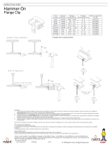
nVent CSBS1 is a single-sided flange attachment designed to provide a secure and versatile mounting solution for various piping and support systems. It offers the flexibility to attach sway brace assemblies to structures in multiple orientations, ensuring proper alignment and stability. The CSBS1 is suitable for use with a wide range of flange thicknesses, making it adaptable to different structural requirements. Its compatibility with industry-standard hardware simplifies the installation process.

nVent CSBS1 is a single-sided flange attachment designed to provide a secure and versatile mounting solution for various piping and support systems. It offers the flexibility to attach sway brace assemblies to structures in multiple orientations, ensuring proper alignment and stability. The CSBS1 is suitable for use with a wide range of flange thicknesses, making it adaptable to different structural requirements. Its compatibility with industry-standard hardware simplifies the installation process.

Parallel to Structure
Parallel to Beam
Parallel to Structure
Perpendicular to Beam
Perpendicular to Structure
Perpendicular to Beam
Installation Angle
from Vertical
Installation Angle
Longitudinal
to Structure
Installation Angle
from Vertical
Lateral
to Structure
CSBS1/CSBS2
CSBS1A
Section View
Structure Attachment Fittings are not Included with the CSBS1 or the CSBS2
1.
*Part Number are EG Plating. Other Coatings are available.
The required type, number and size of fasteners used for the
structure attachment fitting shall be in accordance with NFPA 13.
Sway brace assemblies are intended to be installed in accordance
with NFPA 13 and the manufacturer's installation instructions .
UL Loads (Listed for Structural Attachment)
Part Number
Structure
Attachment Fitting
Flange Thickness
Parallel to Structure
Perpendicular to Beam
Perpendicular to Structure
Perpendicular to Beam
Parallel to Structure
Parallel to Beam
Global
Article
Inch
mm
CSBS1
404504
CSBU1
1/4 to 5/16
6 to 8
1,500 lb (6,672 N)
3/8 to 3/4
8 to 19
1,885 lb (8,385 N)
CSBURC12
1/4 to 3/4
6 to 19
1,100 lb (4,893 N)
CSBS1A
404505
CSBU1
1/4 to 5/16
6 to 8
1,500 lb (6,672 N)
3/8 to 3/4
8 to 19
1,885 lb (8,385 N)
CSBS2
404506
CSBU1
3/4 to 1-1/4
19 to 31
1,704 lb (7580 N)
CSBURC12
1,100 lb (4,893 N)
*Part Number
Flange Thickness
Global
Article
Inch
mm
CSBS1
404504
1/4 to 3/4
6 to 19
CSBS1A
404505
CSBS2
404506
3/4 to 1-1/4
19 to 31
TECHNICAL SUPPORT:
www.nVent.com
CFS541_G
INSTRUCTION SHEET
1 OF 3
© 2016-2020 nVent All Rights Reserved


WARNING:
nVent products shall be installed and used only as indicated in nVent product instruction sheets and training materials. Instruction sheets are available at
1.
www.nVent.com
and from your nVent customer service representative.
nVent products must never be used for a purpose other than the purpose for which they were designed or in a manner that exceeds specified load ratings.
2.
All instructions must be
completely
followed to ensure proper and safe installation and performance.
3.
Improper installation, misuse, misapplication or other failure to completely follow nVent's instructions and warnings may cause product malfunction, property
4.
damage, serious bodily injury and/or death, and void your warranty.
Products that are manufactured using spring steel components shall be used only in a non-corrosive indoor environment.
5.
All pipe supports, hangers, intermediate components and structural attachments must ONLY be used as described herein and are NEVER to be used for any
6.
other purpose.
NOTE: All load ratings are for static conditions and do not account for dynamic loading such as wind, water or seismic loads, unless otherwise noted.
The customer is responsible for:
a. Conformance to all governing codes.
b. The integrity of structures to which the products are attached, including their capability of safely accepting the loads imposed, as evaluated by a qualified
engineer.
c. Using appropriate industry standard hardware as noted above.
SAFETY INSTRUCTIONS:
All governing codes and regulations and those required by the job site must be observed.
Always use appropriate safety equipment such as eye protection, hard hat, and gloves as appropriate to the application.
nVent, nVent CADDY, nVent ERICO Cadweld, nVent ERICO Critec, nVent ERICO, nVent ERIFLEX, and nVent LENTON are
owned by nVent or its global affiliates. All other trademarks are the property of their respective owners. nVent reserves the
right to change specifications without prior notice.
Minimum Install Torque
50ft-lb(75 N-m)
Attach CSBU1
6.00
152.4
max
Note: Alternate torque
between bolts evenly
Push against
flange fully
Shear off
Shear off
12
3
4
FM Approved when used with 1", 1-1/4", 1-1/2", or 2" (DN25, DN32, DN40, DN50) NPS Schedule 40, GB/T 3091,
1.
EN 10255 (Heavy), AS 1074 Heavy or JIS G3454 brace pipe.
Part Number
Orientation
FM Horizontal Load Ratings
Global
Article
Installation Angle
30
- 44
45
- 59
60
- 74
75
- 90
CSBS1
404504
Lateral
850 lb
(3,780 N)
1780 lb
(7,910 N)
2,770 lb
(12,320 N)
2,840 lb
(12,630 N)
CSBS1A
404505
CSBS2
404506
1,220 lb
(5,420 N)
2,140 lb
(9,510 N)
2,580 lb
(11,470 N)
2,870 lb
(12,760 N)
CSBS1
404504
Longitudinal
880 lb
(3910 N)
1,430 lb
(6,360 N)
2,020 lb
(8,980 N)
2,410 lb
(10,720 N)
CSBS1A
404505
CSBS2
404506
1,100 lb
(4,890 N)
1,820 lb
(8,090 N)
2,190 lb
(9,740 N)
2,680 lb
(11,920 N)
TECHNICAL SUPPORT:
www.nVent.com
CFS541_G
INSTRUCTION SHEET
2 OF 3
© 2016-2020 nVent All Rights Reserved
nVent, nVent CADDY, nVent ERICO Cadweld, nVent ERICO Critec, nVent ERICO, nVent ERIFLEX, and nVent LENTON are
owned by nVent or its global affiliates. All other trademarks are the property of their respective owners. nVent reserves the
right to change specifications without prior notice.
.875
22.23
min gap
With CSBU1
CSBS1A
I-Beam - Bottom Flange
Tapered and Non-
Tapered Flange
Bar Joist - Top Chord Horizontal Leg
I-Beam - Top Flange
Tapered and Non-Tapered Flange
Bar Joist - Top Chord Vertical Leg
I-Beam - Bottom Flange
Non-Tapered Flanges Only
I-Beam
Tapered Flanges
Note: Cone point set
screw must be installed
on tapered flange side
TECHNICAL SUPPORT:
www.nVent.com
CFS541_G
INSTRUCTION SHEET
3 OF 3
© 2016-2020 nVent All Rights Reserved
nVent, nVent CADDY, nVent ERICO Cadweld, nVent ERICO Critec, nVent ERICO, nVent ERIFLEX, and nVent LENTON are
owned by nVent or its global affiliates. All other trademarks are the property of their respective owners. nVent reserves the
right to change specifications without prior notice.
  • Page 1 1
  • Page 2 2
  • Page 3 3

nvent CSBS1 Operating instructions

Type
Operating instructions

nVent CSBS1 is a single-sided flange attachment designed to provide a secure and versatile mounting solution for various piping and support systems. It offers the flexibility to attach sway brace assemblies to structures in multiple orientations, ensuring proper alignment and stability. The CSBS1 is suitable for use with a wide range of flange thicknesses, making it adaptable to different structural requirements. Its compatibility with industry-standard hardware simplifies the installation process.

Ask a question and I''ll find the answer in the document

Finding information in a document is now easier with AI