Design Guide | Communications between controllers and AK-SM 800A
© Danfoss | Climate Solutions | 2022.10 AJ430138910308en-000101 | 6
3. Requirement to installation
Cable type
Cables with twisted in pairs must be used, and they may be
provided with a screen.
Some types of communication require a cable with a screen to be
used.
Examples
• For Lon RS485, Modbus, RS485 Third party - General 'EIA 485'
recommendation:
– Belden 9841, 24 AWG, 1 pair with screen
– Belden 3107A, 22 AWG, 2 pairs with screen
– Alpha wire 6453, 22 AWG, 1 pair with screen
– Carol C4841A, 24 AWG, 1 pair with screen
– Dätwyler Uninet 3002 4P 4 pairs with screen(CAT5 cable)
– Belden 7703NH, 22 AWG, 1 pair with screen
– Belden 7704NH, 22 AWG, 2 pair with screen
– LIYCY (TP) 2X0,5, 20 AWG 1 Pair with screen
– LIYCY (TP) 2X2X0,5, 20 AWG 2 Pair with screen
• For IP Fieldbus cable
ANSI/TIA 568 B/C CAT5e UTP or STP cable w/RJ45 connectors.
Wires with larger cross-section than AWG 20 / 0.52 mm is not
recommended.
Conductors
The wires in the cable that is connected to the controller must
be correct. Although there are four wires in the cable inside the
screen, you cannot simply choose colours freely. The wires are
twisted in pairs, i.e. 2 and 2, and you must use a pair that is twisted
around each other.
If there are several “vacant” wires in the cable, they must be used
for nothing else than data communication. We recommend to use
separate cables for dierent bus type.
Cable length
• A cable length must not exceed 1200 m / 4000 ft.
• A repeater must be used for longer lengths than 1200 m / 4000 ft.
• For IP-eldbus Maximum length should be 100 m / 330 ft, if
longer you need to use a switch in between.
See the additional requirements for the respective communication
forms.
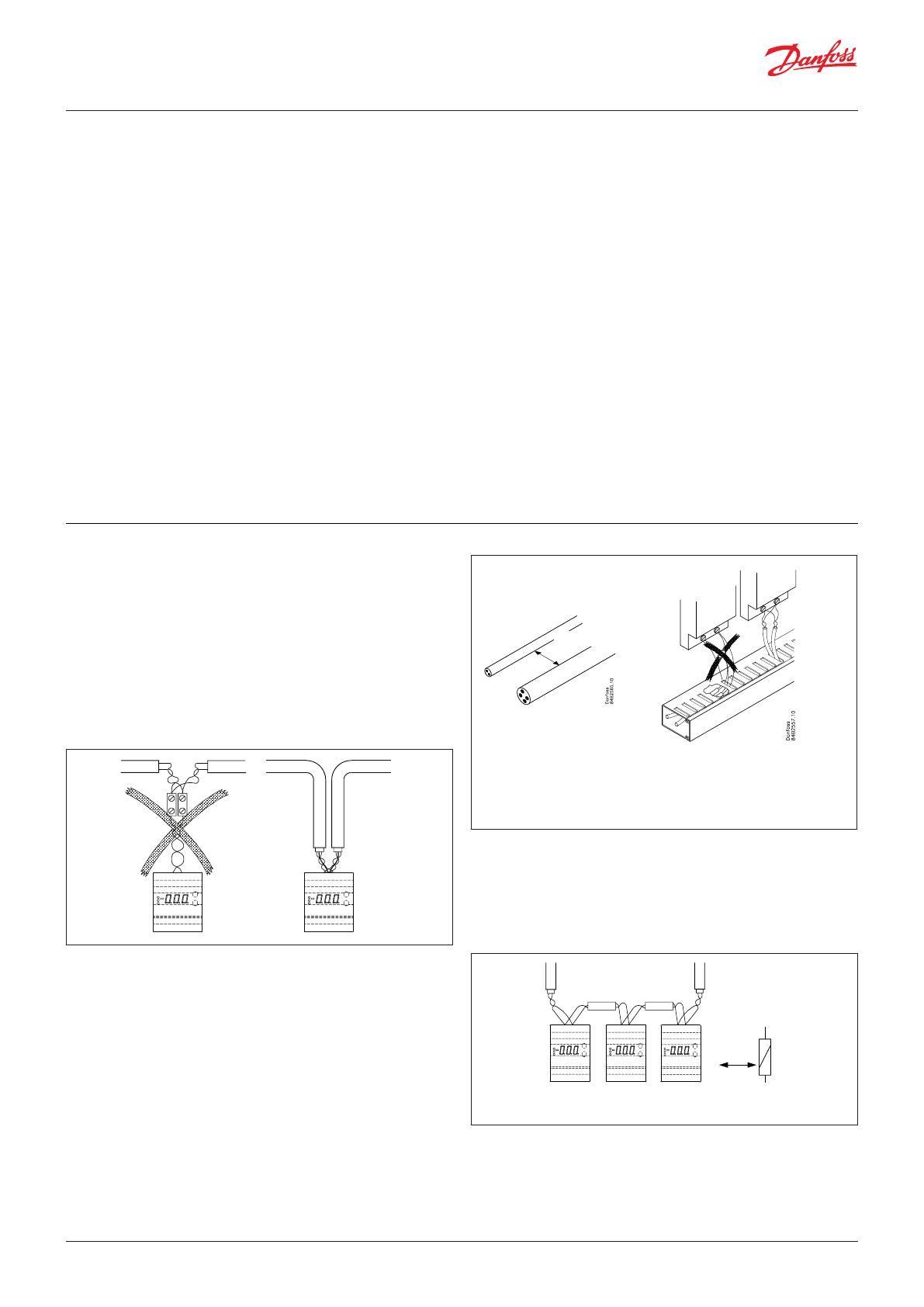
Cable tray
When the cable is ducted with
other cables, there is a strong
risk that electrical noise will be
transferred. Keep away from live
cables.
When the cable is ducted in a cable
tray, the cable must be fed out and
right up to the controller. The fast
solution where only wires are fed
out will cause problems.
Min.10 – 15 cm
Max. 3 – 4 cm
Cabinet mounting
When controllers are installed in a cabinet, internal cable ducting
must also comply with the relevant requirements. Use this cable
ducting when one or more controllers are installed in a cabinet.
(The short connections between controllers must also be of the
correct cable types.)
Min.
10 – 15 cm
Keep a distance to relays, their cables and other things
emitting electric noises.
When controllers are tted in a cabinet door, the cables are usually
kept together in bundles of cables. Here the bundle with data
communication, display and digital input signals must be kept
separate from other cables that emit noise.
IMPORTANT!
Our experience indicates that problems can occur with
communication due to the following weaknesses:
Long wire ends
Do not strip more of the cable insulation than strictly neces sary.
Max. 3 – 4 cm. Continue the twisting of the cables right up to the
terminals.
Stubs
Avoid stubs on the cable. Feed the cable right to the end and then
back again.
Danfoss
80G8410
Noise sources
Keep the cable away from electrical noise sources and power
cables (relays, contactors and especially electronic ballast for strip
lights are strong noise sources). A distance of at least 10 – 15 cm
will be sucient.
Cable length extremities
Each section of data communication must be terminated correctly.
See the relevant communication form on the following pages.
Termination with a resistance of 120 . Either directly on the
terminals or with a switch.
Screen
See the respective communication forms in the section 3.0 or the
respective controller.


