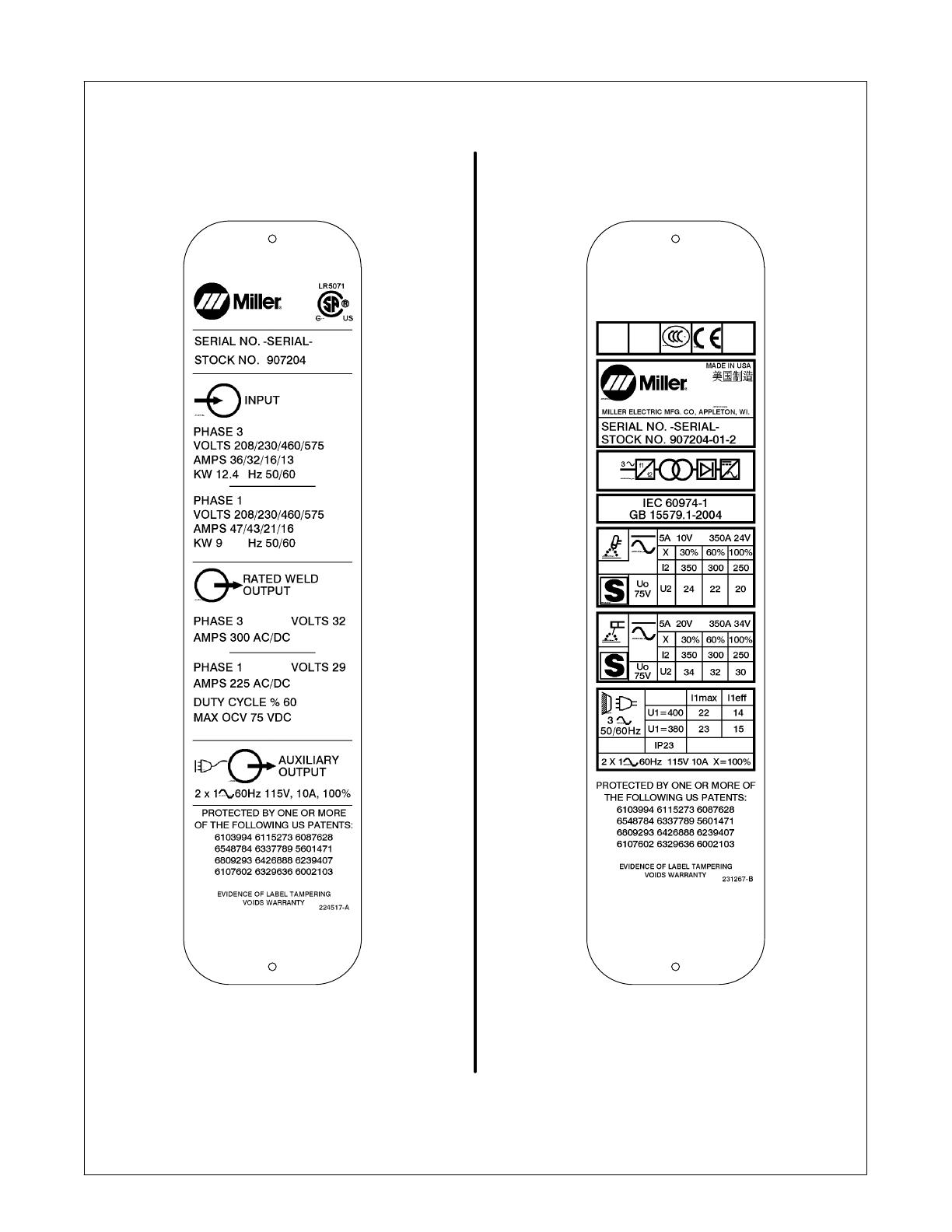
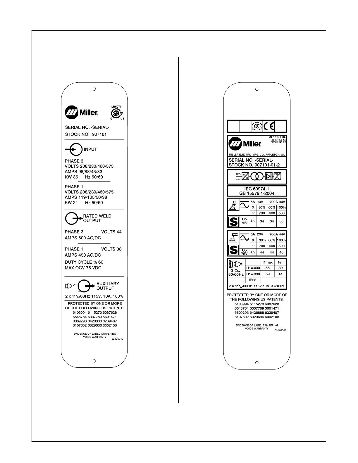
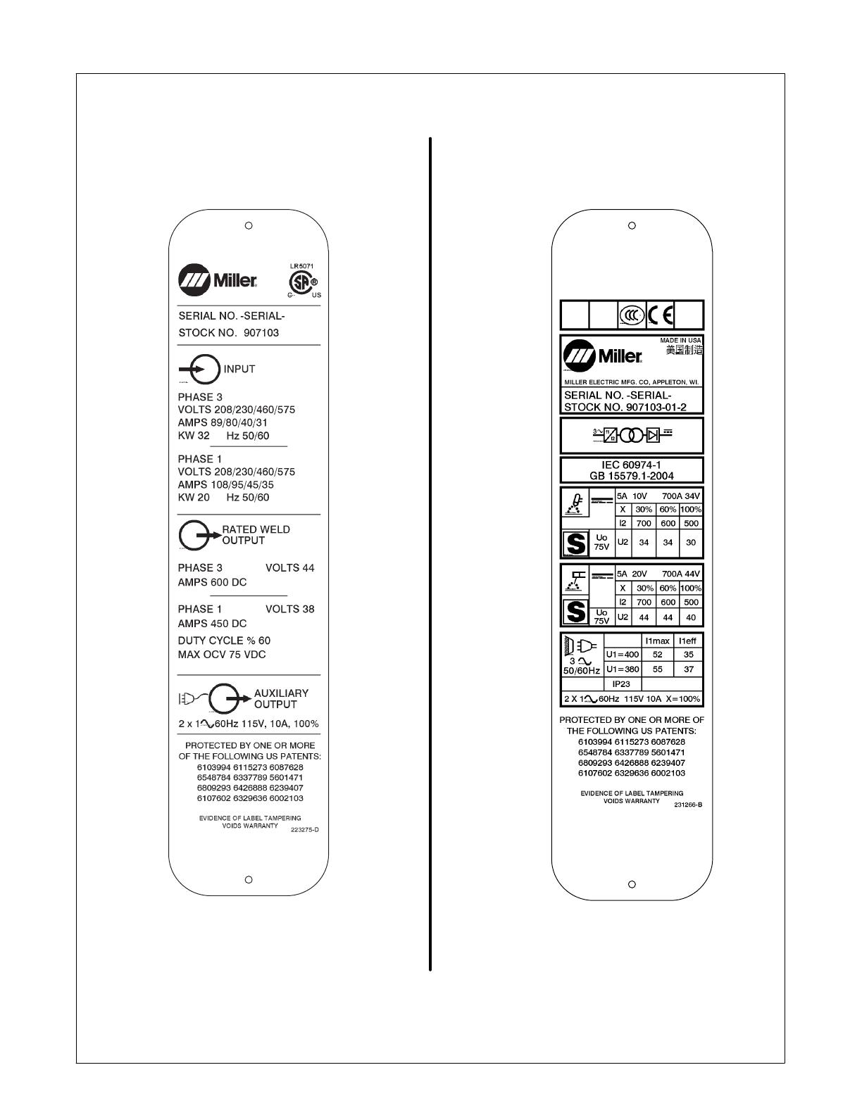
Processes
Description
TIG (GTAW) Welding
Stick (SMAW) Welding
Arc Welding Power Source
OM-216 869G
200802
Dynasty 350, 700
208/575 Volt Models W/Auto-Line
Visit our website at
www.MillerWelds.com
Maxstar 350, 700
File: TIG (GTAW)
Including Optional Cart And Cooler
Miller Electric manufactures a full line
of welders and welding related equipment.
For information on other quality Miller
products, contact your local Miller distributor to receive the latest full
line catalog or individual specification sheets. To locate your nearest
distributor or service agency call 1-800-4-A-Miller, or visit us at
www.MillerWelds.com on the web.
Thank you and congratulations on choosing Miller. Now you can get
the job done and get it done right. We know you don’t have time to do
it any other way.
That’s why when Niels Miller first started building arc welders in 1929,
he made sure his products offered long-lasting value and superior
quality. Like you, his customers couldn’t afford anything less. Miller
products had to be more than the best they could be. They had to be the
best you could buy.
Today, the people that build and sell Miller products continue the
tradition. They’re just as committed to providing equipment and service
that meets the high standards of quality and value established in 1929.
This Owners Manual is designed to help you get the most out of your
Miller products. Please take time to read the Safety precautions. They
will help you protect yourself against potential hazards on the worksite.
We’ve made installation and operation quick
and easy. With Miller you can count on years
of reliable service with proper maintenance.
And if for some reason the unit needs repair,
there’s a Troubleshooting section that will
help you figure out what the problem is. The
parts list will then help you to decide the
exact part you may need to fix the problem.
Warranty and service information for your
particular model are also provided.
Miller is the first welding
equipment manufacturer in
the U.S.A. to be registered to
the ISO 9001:2000 Quality
System Standard.
Working as hard as you do
every power source from
Miller is backed by the most
hassle-free warranty in the
business.
From Miller to You
Mil_Thank 4/05
TABLE OF CONTENTS
SECTION 1 SAFETY PRECAUTIONS - READ BEFORE USING 1 . . . . . . . . . . . . . . . . . . . . . . . . . . . . . . . . .
1-1. Symbol Usage 1 . . . . . . . . . . . . . . . . . . . . . . . . . . . . . . . . . . . . . . . . . . . . . . . . . . . . . . . . . . . . . . . . . . . . . . .
1-2. Arc Welding Hazards 1 . . . . . . . . . . . . . . . . . . . . . . . . . . . . . . . . . . . . . . . . . . . . . . . . . . . . . . . . . . . . . . . . .
1-3. Additional Symbols For Installation, Operation, And Maintenance 3 . . . . . . . . . . . . . . . . . . . . . . . . . . . .
1-4. California Proposition 65 Warnings 4 . . . . . . . . . . . . . . . . . . . . . . . . . . . . . . . . . . . . . . . . . . . . . . . . . . . . . .
1-5. Principal Safety Standards 4 . . . . . . . . . . . . . . . . . . . . . . . . . . . . . . . . . . . . . . . . . . . . . . . . . . . . . . . . . . . .
1-6. EMF Information 4 . . . . . . . . . . . . . . . . . . . . . . . . . . . . . . . . . . . . . . . . . . . . . . . . . . . . . . . . . . . . . . . . . . . . .
SECTION 2 CONSIGNES DE SÉCURITÉ LIRE AVANT UTILISATION 5 . . . . . . . . . . . . . . . . . . . . . . . . . .
2-1. Symboles utilisés 5 . . . . . . . . . . . . . . . . . . . . . . . . . . . . . . . . . . . . . . . . . . . . . . . . . . . . . . . . . . . . . . . . . . . .
2-2. Dangers relatifs au soudage à l’arc 5 . . . . . . . . . . . . . . . . . . . . . . . . . . . . . . . . . . . . . . . . . . . . . . . . . . . . .
2-3. Dangers supplémentaires en relation avec l’installation, le fonctionnement et la maintenance 7 . . . . .
2-4. Proposition californienne 65 Avertissements 8 . . . . . . . . . . . . . . . . . . . . . . . . . . . . . . . . . . . . . . . . . . . . . .
2-5. Principales normes de sécurité 9 . . . . . . . . . . . . . . . . . . . . . . . . . . . . . . . . . . . . . . . . . . . . . . . . . . . . . . . . .
2-6. Information EMF 9 . . . . . . . . . . . . . . . . . . . . . . . . . . . . . . . . . . . . . . . . . . . . . . . . . . . . . . . . . . . . . . . . . . . . .
SECTION 3 DEFINITIONS (CE Models Only) 11 . . . . . . . . . . . . . . . . . . . . . . . . . . . . . . . . . . . . . . . . . . . . . . . . .
3-1. Warning Label Definitions 11 . . . . . . . . . . . . . . . . . . . . . . . . . . . . . . . . . . . . . . . . . . . . . . . . . . . . . . . . . . . . .
3-2. Manufacturers Rating Labels For Dynasty 350 Models 14 . . . . . . . . . . . . . . . . . . . . . . . . . . . . . . . . . . . . .
3-3. Manufacturers Rating Labels For Maxstar 350 Models 15 . . . . . . . . . . . . . . . . . . . . . . . . . . . . . . . . . . . . .
3-4. Manufacturers Rating Labels For Dynasty 700 Models 16 . . . . . . . . . . . . . . . . . . . . . . . . . . . . . . . . . . . . .
3-5. Manufacturers Rating Labels For Maxstar 700 Models 17 . . . . . . . . . . . . . . . . . . . . . . . . . . . . . . . . . . . . .
3-6. Symbols And Definitions 18 . . . . . . . . . . . . . . . . . . . . . . . . . . . . . . . . . . . . . . . . . . . . . . . . . . . . . . . . . . . . . .
SECTION 4 INSTALLATION 19 . . . . . . . . . . . . . . . . . . . . . . . . . . . . . . . . . . . . . . . . . . . . . . . . . . . . . . . . . . . . . . . .
4-1. Specifications 19 . . . . . . . . . . . . . . . . . . . . . . . . . . . . . . . . . . . . . . . . . . . . . . . . . . . . . . . . . . . . . . . . . . . . . . .
4-2. Duty Cycle and Overheating 21 . . . . . . . . . . . . . . . . . . . . . . . . . . . . . . . . . . . . . . . . . . . . . . . . . . . . . . . . . . .
4-3. Volt-Ampere Curves 22 . . . . . . . . . . . . . . . . . . . . . . . . . . . . . . . . . . . . . . . . . . . . . . . . . . . . . . . . . . . . . . . . . .
4-4. Selecting A Location 24 . . . . . . . . . . . . . . . . . . . . . . . . . . . . . . . . . . . . . . . . . . . . . . . . . . . . . . . . . . . . . . . . . .
4-5. Tipping Warnings 24 . . . . . . . . . . . . . . . . . . . . . . . . . . . . . . . . . . . . . . . . . . . . . . . . . . . . . . . . . . . . . . . . . . . .
4-6. Dimensions, Weights And Base Mounting Hole Layout 25 . . . . . . . . . . . . . . . . . . . . . . . . . . . . . . . . . . . . .
4-7. Electrical Service Guide 26 . . . . . . . . . . . . . . . . . . . . . . . . . . . . . . . . . . . . . . . . . . . . . . . . . . . . . . . . . . . . . . .
4-8. Connecting Input Power For 350 Models 30 . . . . . . . . . . . . . . . . . . . . . . . . . . . . . . . . . . . . . . . . . . . . . . . . .
4-9. Connecting Input Power For 700 Models 32 . . . . . . . . . . . . . . . . . . . . . . . . . . . . . . . . . . . . . . . . . . . . . . . . .
4-10. Weld Output Terminals And Selecting Cable Sizes* 34 . . . . . . . . . . . . . . . . . . . . . . . . . . . . . . . . . . . . . . . .
4-11. Remote 14 Receptacle Information (Used Without Automation Connection) 35 . . . . . . . . . . . . . . . . . . . .
4-12. Automation Connection (For 28-Pin Receptacle If Present) 36 . . . . . . . . . . . . . . . . . . . . . . . . . . . . . . . . . .
4-13. Remote Memory Select Inputs (For 28-Pin Receptacle If Present) 37 . . . . . . . . . . . . . . . . . . . . . . . . . . . .
4-14. Automation Selections (For 28-Pin Receptacle If Present) 37 . . . . . . . . . . . . . . . . . . . . . . . . . . . . . . . . . .
4-15. Typical Automation Application 38 . . . . . . . . . . . . . . . . . . . . . . . . . . . . . . . . . . . . . . . . . . . . . . . . . . . . . . . . .
4-16. 115 Volts AC Duplex Receptacle, Supplementary Protector CB1, And Power Switch 38 . . . . . . . . . . . .
4-17. Gas Connections 39 . . . . . . . . . . . . . . . . . . . . . . . . . . . . . . . . . . . . . . . . . . . . . . . . . . . . . . . . . . . . . . . . . . . .
4-18. TIG HF Impulse/ Lift-Arct Connections 39 . . . . . . . . . . . . . . . . . . . . . . . . . . . . . . . . . . . . . . . . . . . . . . . . . . .
4-19. Cooler Connections 40 . . . . . . . . . . . . . . . . . . . . . . . . . . . . . . . . . . . . . . . . . . . . . . . . . . . . . . . . . . . . . . . . . .
4-20. Dynasty Stick Connections 41 . . . . . . . . . . . . . . . . . . . . . . . . . . . . . . . . . . . . . . . . . . . . . . . . . . . . . . . . . . . .
4-21. Maxstar Stick Connections 41 . . . . . . . . . . . . . . . . . . . . . . . . . . . . . . . . . . . . . . . . . . . . . . . . . . . . . . . . . . . .
TABLE OF CONTENTS
SECTION 5 OPERATION 42 . . . . . . . . . . . . . . . . . . . . . . . . . . . . . . . . . . . . . . . . . . . . . . . . . . . . . . . . . . . . . . . . . .
5-1. Controls 42 . . . . . . . . . . . . . . . . . . . . . . . . . . . . . . . . . . . . . . . . . . . . . . . . . . . . . . . . . . . . . . . . . . . . . . . . . . . .
5-2. Encoder Control 43 . . . . . . . . . . . . . . . . . . . . . . . . . . . . . . . . . . . . . . . . . . . . . . . . . . . . . . . . . . . . . . . . . . . . .
5-3. Amperage Control 43 . . . . . . . . . . . . . . . . . . . . . . . . . . . . . . . . . . . . . . . . . . . . . . . . . . . . . . . . . . . . . . . . . . . .
5-4. Ammeter And Parameter Display 43 . . . . . . . . . . . . . . . . . . . . . . . . . . . . . . . . . . . . . . . . . . . . . . . . . . . . . . .
5-5. Voltmeter And Selected Parameter Display 44 . . . . . . . . . . . . . . . . . . . . . . . . . . . . . . . . . . . . . . . . . . . . . . .
5-6. Polarity Control (Dynastyt Models Only) 44 . . . . . . . . . . . . . . . . . . . . . . . . . . . . . . . . . . . . . . . . . . . . . . . . .
5-7. Process Control 45 . . . . . . . . . . . . . . . . . . . . . . . . . . . . . . . . . . . . . . . . . . . . . . . . . . . . . . . . . . . . . . . . . . . . .
5-8. Lift-ArcE And HF TIG Start Procedures 45 . . . . . . . . . . . . . . . . . . . . . . . . . . . . . . . . . . . . . . . . . . . . . . . . . .
5-9. Output Control 46 . . . . . . . . . . . . . . . . . . . . . . . . . . . . . . . . . . . . . . . . . . . . . . . . . . . . . . . . . . . . . . . . . . . . . . .
5-10. Pulser Control 47 . . . . . . . . . . . . . . . . . . . . . . . . . . . . . . . . . . . . . . . . . . . . . . . . . . . . . . . . . . . . . . . . . . . . . . .
5-11. Sequencer Controls 48 . . . . . . . . . . . . . . . . . . . . . . . . . . . . . . . . . . . . . . . . . . . . . . . . . . . . . . . . . . . . . . . . . .
5-12. Gas/DIG Controls (Preflow/Post Flow/DIG/Purge) 49 . . . . . . . . . . . . . . . . . . . . . . . . . . . . . . . . . . . . . . . . .
5-13. AC Waveshape (Dynasty Models Only) 50 . . . . . . . . . . . . . . . . . . . . . . . . . . . . . . . . . . . . . . . . . . . . . . . . . .
5-14. Memory (Program Storage Locations 1-9) 51 . . . . . . . . . . . . . . . . . . . . . . . . . . . . . . . . . . . . . . . . . . . . . . . .
5-15. Factory Parameter Defaults And Range And Resolution For 350 Models 52 . . . . . . . . . . . . . . . . . . . . . .
5-16. Factory Parameter Defaults And Range And Resolution For 700 Models 53 . . . . . . . . . . . . . . . . . . . . . .
5-17. Resetting Unit To Factory Default Settings 54 . . . . . . . . . . . . . . . . . . . . . . . . . . . . . . . . . . . . . . . . . . . . . . .
5-18. Software And Revision Viewing 54 . . . . . . . . . . . . . . . . . . . . . . . . . . . . . . . . . . . . . . . . . . . . . . . . . . . . . . . .
5-19. Arc Timer/Counter Display 55 . . . . . . . . . . . . . . . . . . . . . . . . . . . . . . . . . . . . . . . . . . . . . . . . . . . . . . . . . . . . .
SECTION 6 ADVANCED FUNCTIONS 56 . . . . . . . . . . . . . . . . . . . . . . . . . . . . . . . . . . . . . . . . . . . . . . . . . . . . . . .
6-1. Accessing Advanced Functions 56 . . . . . . . . . . . . . . . . . . . . . . . . . . . . . . . . . . . . . . . . . . . . . . . . . . . . . . . .
6-2. Programmable TIG Start Parameters 57 . . . . . . . . . . . . . . . . . . . . . . . . . . . . . . . . . . . . . . . . . . . . . . . . . . . .
6-3. Output Control And Trigger Functions 58 . . . . . . . . . . . . . . . . . . . . . . . . . . . . . . . . . . . . . . . . . . . . . . . . . . .
6-4. AC Waveshape Selection (Dynasty Models Only) 63 . . . . . . . . . . . . . . . . . . . . . . . . . . . . . . . . . . . . . . . . .
6-5. Independent Amplitude Selection 64 . . . . . . . . . . . . . . . . . . . . . . . . . . . . . . . . . . . . . . . . . . . . . . . . . . . . . . .
6-6. Spot Enable 64 . . . . . . . . . . . . . . . . . . . . . . . . . . . . . . . . . . . . . . . . . . . . . . . . . . . . . . . . . . . . . . . . . . . . . . . . .
6-7. Stick Open-Circuit Voltage (OCV) Selection 64 . . . . . . . . . . . . . . . . . . . . . . . . . . . . . . . . . . . . . . . . . . . . . .
6-8. Lockout Functions 65 . . . . . . . . . . . . . . . . . . . . . . . . . . . . . . . . . . . . . . . . . . . . . . . . . . . . . . . . . . . . . . . . . . .
6-9. Setting Unit So Meters Are Blank While Pulse Welding 67 . . . . . . . . . . . . . . . . . . . . . . . . . . . . . . . . . . . . .
SECTION 7 MAINTENANCE AND TROUBLESHOOTING 68 . . . . . . . . . . . . . . . . . . . . . . . . . . . . . . . . . . . . . .
7-2. Blowing Out Inside of Unit 69 . . . . . . . . . . . . . . . . . . . . . . . . . . . . . . . . . . . . . . . . . . . . . . . . . . . . . . . . . . . . .
7-3. Coolant Maintenance And Oiling Motor 69 . . . . . . . . . . . . . . . . . . . . . . . . . . . . . . . . . . . . . . . . . . . . . . . . . .
7-4. Troubleshooting 70 . . . . . . . . . . . . . . . . . . . . . . . . . . . . . . . . . . . . . . . . . . . . . . . . . . . . . . . . . . . . . . . . . . . . .
SECTION 8 ELECTRICAL DIAGRAM 72 . . . . . . . . . . . . . . . . . . . . . . . . . . . . . . . . . . . . . . . . . . . . . . . . . . . . . . . .
SECTION 9 HIGH FREQUENCY 85 . . . . . . . . . . . . . . . . . . . . . . . . . . . . . . . . . . . . . . . . . . . . . . . . . . . . . . . . . . . .
9-1. Welding Processes Requiring High Frequency 85 . . . . . . . . . . . . . . . . . . . . . . . . . . . . . . . . . . . . . . . . . . . .
9-2. Incorrect Installation 85 . . . . . . . . . . . . . . . . . . . . . . . . . . . . . . . . . . . . . . . . . . . . . . . . . . . . . . . . . . . . . . . . . .
9-3. Correct Installation 86 . . . . . . . . . . . . . . . . . . . . . . . . . . . . . . . . . . . . . . . . . . . . . . . . . . . . . . . . . . . . . . . . . . .
SECTION 10 SELECTING AND PREPARING A TUNGSTEN FOR DC OR AC WELDING WITH INVERTER
MACHINES 87 . . . . . . . . . . . . . . . . . . . . . . . . . . . . . . . . . . . . . . . . . . . . . . . . . . . . . . . . . . . . . . . . . . . . . . . . . . . . . . . .
10-1. Selecting Tungsten Electrode (Wear Clean gloves To Prevent Contamination Of Tungsten) 87 . . . . . . .
10-2. Preparing Tungsten Electrode For DC Electrode Negative (DCEN) Welding Or AC Welding With Inverter
Machines 87 . . . . . . . . . . . . . . . . . . . . . . . . . . . . . . . . . . . . . . . . . . . . . . . . . . . . . . . . . . . . . . . . . . . . . . . . . . .
SECTION 11 GUIDELINES FOR TIG WELDING (GTAW) 88 . . . . . . . . . . . . . . . . . . . . . . . . . . . . . . . . . . . . . . .
11-1. Positioning The Torch 88 . . . . . . . . . . . . . . . . . . . . . . . . . . . . . . . . . . . . . . . . . . . . . . . . . . . . . . . . . . . . . . . . .
11-2. Torch Movement During Welding 89 . . . . . . . . . . . . . . . . . . . . . . . . . . . . . . . . . . . . . . . . . . . . . . . . . . . . . . .
11-3. Positioning Torch Tungsten For Various Weld Joints 89 . . . . . . . . . . . . . . . . . . . . . . . . . . . . . . . . . . . . . . .
SECTION 12 SETUP GUIDES FOR (GTAW) TIG WELDING 90 . . . . . . . . . . . . . . . . . . . . . . . . . . . . . . . . . . . . .
12-1. Typical GTAW Setups 90 . . . . . . . . . . . . . . . . . . . . . . . . . . . . . . . . . . . . . . . . . . . . . . . . . . . . . . . . . . . . . . . .
SECTION 13 SETUP GUIDES FOR (SMAW) STICK WELDING 92 . . . . . . . . . . . . . . . . . . . . . . . . . . . . . . . . . .
13-1. Front Panel Display For Stick DCEP (Direct Current Electrode Positive) 92 . . . . . . . . . . . . . . . . . . . . . .
SECTION 14 STICK WELDING (SMAW) GUIDELINES 93 . . . . . . . . . . . . . . . . . . . . . . . . . . . . . . . . . . . . . . . . .
SECTION 15 PARTS LIST FOR 350 MODELS 102 . . . . . . . . . . . . . . . . . . . . . . . . . . . . . . . . . . . . . . . . . . . . . . . .
SECTION 16 PARTS LIST FOR 700 MODELS 112 . . . . . . . . . . . . . . . . . . . . . . . . . . . . . . . . . . . . . . . . . . . . . . . .
SECTION 17 PARTS LIST FOR COOLER 122 . . . . . . . . . . . . . . . . . . . . . . . . . . . . . . . . . . . . . . . . . . . . . . . . . . . .
SECTION 18 PARTS LIST FOR CART 124 . . . . . . . . . . . . . . . . . . . . . . . . . . . . . . . . . . . . . . . . . . . . . . . . . . . . . . .
OPTIONS AND ACCESSORIES
WARRANTY
dec_stat_1/07
Declaration of Conformity for
European Community (CE) Products
This information is provided for units with CE certification (see rating label on unit).
Manufacturer: European Contact:
Miller Electric Mg. Co. Mr. Danilo Fedolfi,
1635 W. Spencer St. Managing Director
Appleton, WI 54914 USA ITW Welding Products Italy S.r.l.
Phone: (920) 734-9821 Via Privata Iseo 6/E
20098 San Giuliano
Milanese, Italy
Phone: 39(02)98290-1
Fax: 39(02)98290203
European Contact Signature:
Declares that this product: Dynasty® 350
conforms to the following Directives and Standards:
Directives
Low Voltage Directive: 73/23/EEC, 2006/95/EC
Electromagnetic Compatibility Directives: 89/336/EEC, 92/31/EEC, 2004/108/EC
Machinery Directives: 98/37EEC, 91/368/EEC, 92/31/EEC, 133/04, 93/68/EEC
CE Marking Directive: 93/68/EEC
Standards
Arc Welding Equipment Part 1: Welding Power Sources. IEC 60974-1 Ed. 3, 2005-07
Arc Welding Equipment Part 10: Electromagnetic Compatibility (EMC) Requirements.
IEC 60974-10 Ed. 1.1, 2004-10
Degrees of Protection Provided By Enclosures (IP Code): IEC 60529 Ed. 2.1, 2001-02
Arc Welding Equipment Part 3: Arc Striking And Stabilizing Devices. IEC 60974-3 Ed. 1, 2003-07
The product technical file is maintained by the responsible Business Unit(s) located at the manufacturing facility.
dec_stat_1/07
Declaration of Conformity for
European Community (CE) Products
This information is provided for units with CE certification (see rating label on unit).
Manufacturer: European Contact:
Miller Electric Mg. Co. Mr. Danilo Fedolfi,
1635 W. Spencer St. Managing Director
Appleton, WI 54914 USA ITW Welding Products Italy S.r.l.
Phone: (920) 734-9821 Via Privata Iseo 6/E
20098 San Giuliano
Milanese, Italy
Phone: 39(02)98290-1
Fax: 39(02)98290203
European Contact Signature:
Declares that the product: Dynasty
700
conforms to the following Directives and Standards:
Directives
Low Voltage Directive: 73/23/EEC, 2006/95/EC
Electromagnetic Compatibility Directives: 89/336/EEC, 92/31/EEC, 2004/108/EC
Machinery Directives: 98/37EEC, 91/368/EEC, 92/31/EEC, 133/04, 93/68/EEC
CE Marking Directive: 93/68/EEC
Standards
Arc Welding Equipment Part 1: Welding Power Sources. IEC 60974-1 Ed. 3, 2005-07
Arc Welding Equipment Part 10: Electromagnetic Compatibility (EMC) Requirements.
IEC 60974-10 Ed. 1.1, 2004-10
Degrees of Protection Provided By Enclosures (IP Code): IEC 60529 Ed. 2.1, 2001-02
Arc Welding Equipment Part 3: Arc Striking And Stabilizing Devices. IEC 60974-3 Ed. 1, 2003-07
The product technical file is maintained by the responsible Business Unit(s) located at the manufacturing facility.
dec_stat_1/07
Declaration of Conformity for
European Community (CE) Products
This information is provided for units with CE certification (see rating label on unit).
Manufacturer: European Contact:
Miller Electric Mg. Co. Mr. Danilo Fedolfi,
1635 W. Spencer St. Managing Director
Appleton, WI 54914 USA ITW Welding Products Italy S.r.l.
Phone: (920) 734-9821 Via Privata Iseo 6/E
20098 San Giuliano
Milanese, Italy
Phone: 39(02)98290-1
Fax: 39(02)98290203
European Contact Signature:
Declares that this product: Maxstar®350
conforms to the following Directives and Standards:
Directives
Low Voltage Directive: 73/23/EEC, 2006/95/EC
Electromagnetic Compatibility Directives: 89/336/EEC, 92/31/EEC, 2004/108/EC
Machinery Directives: 98/37EEC, 91/368/EEC, 92/31/EEC, 133/04, 93/68/EEC
CE Marking Directive: 93/68/EEC
Standards
Arc Welding Equipment Part 1: Welding Power Sources. IEC 60974-1 Ed. 3, 2005-07
Arc Welding Equipment Part 10: Electromagnetic Compatibility (EMC) Requirements.
IEC 60974-10 Ed. 1.1, 2004-10
Degrees of Protection Provided By Enclosures (IP Code): IEC 60529 Ed. 2.1, 2001-02
Arc Welding Equipment Part 3: Arc Striking And Stabilizing Devices. IEC 60974-3 Ed. 1, 2003-07
The product technical file is maintained by the responsible Business Unit(s) located at the manufacturing facility.
dec_stat_1/07
Declaration of Conformity for
European Community (CE) Products
This information is provided for units with CE certification (see rating label on unit).
Manufacturer: European Contact:
Miller Electric Mg. Co. Mr. Danilo Fedolfi,
1635 W. Spencer St. Managing Director
Appleton, WI 54914 USA ITW Welding Products Italy S.r.l.
Phone: (920) 734-9821 Via Privata Iseo 6/E
20098 San Giuliano
Milanese, Italy
Phone: 39(02)98290-1
Fax: 39(02)98290203
European Contact Signature:
Declares that the product: Maxstar
700
conforms to the following Directives and Standards:
Directives
Low Voltage Directive: 73/23/EEC, 2006/95/EC
Electromagnetic Compatibility Directives: 89/336/EEC, 92/31/EEC, 2004/108/EC
Machinery Directives: 98/37EEC, 91/368/EEC, 92/31/EEC, 133/04, 93/68/EEC
CE Marking Directive: 93/68/EEC
Standards
Arc Welding Equipment Part 1: Welding Power Sources. IEC 60974-1 Ed. 3, 2005-07
Arc Welding Equipment Part 10: Electromagnetic Compatibility (EMC) Requirements.
IEC 60974-10 Ed. 1.1, 2004-10
Degrees of Protection Provided By Enclosures (IP Code): IEC 60529 Ed. 2.1, 2001-02
Arc Welding Equipment Part 3: Arc Striking And Stabilizing Devices. IEC 60974-3 Ed. 1, 2003-07
The product technical file is maintained by the responsible Business Unit(s) located at the manufacturing facility.
OM-216 869 Page 1
SECTION 1 SAFETY PRECAUTIONS - READ BEFORE USING
som _200704
7
Protect yourself and others from injury — read and follow these precautions.
1-1. Symbol Usage
DANGER! Indicates a hazardous situation which, if
not avoided, will result in death or serious injury. The
possible hazards are shown in the adjoining symbols
or explained in the text.
Indicates a hazardous situation which, if not avoided,
could result in death or serious injury. The possible
hazards are shown in the adjoining symbols or ex-
plained in the text.
NOTICE Indicates statements not related to personal injury.
Indicates special instructions.
This group of symbols means Warning! Watch Out! ELECTRIC
SHOCK, MOVING PARTS, and HOT PARTS hazards. Consult sym-
bols and related instructions below for necessary actions to avoid the
hazards.
1-2. Arc Welding Hazards
The symbols shown below are used throughout this manual
to call attention to and identify possible hazards. When you
see the symbol, watch out, and follow the related instructions
to avoid the hazard. The safety information given below is
only a summary of the more complete safety information
found in the Safety Standards listed in Section 1-5. Read and
follow all Safety Standards.
Only qualified persons should install, operate, maintain, and
repair this unit.
During operation, keep everybody, especially children, away.
ELECTRIC SHOCK can kill.
Touching live electrical parts can cause fatal shocks
or severe burns. The electrode and work circuit is
electrically live whenever the output is on. The input
power circuit and machine internal circuits are also
live when power is on. In semiautomatic or automatic wire welding, the
wire, wire reel, drive roll housing, and all metal parts touching the
welding wire are electrically live. Incorrectly installed or improperly
grounded equipment is a hazard.
Do not touch live electrical parts.
Wear dry, hole-free insulating gloves and body protection.
Insulate yourself from work and ground using dry insulating mats
or covers big enough to prevent any physical contact with the work
or ground.
Do not use AC output in damp areas, if movement is confined, or if
there is a danger of falling.
Use AC output ONLY if required for the welding process.
If AC output is required, use remote output control if present on
unit.
Additional safety precautions are required when any of the follow-
ing electrically hazardous conditions are present: in damp
locations or while wearing wet clothing; on metal structures such
as floors, gratings, or scaffolds; when in cramped positions such
as sitting, kneeling, or lying; or when there is a high risk of unavoid-
able or accidental contact with the workpiece or ground. For these
conditions, use the following equipment in order presented: 1) a
semiautomatic DC constant voltage (wire) welder, 2) a DC manual
(stick) welder, or 3) an AC welder with reduced open-circuit volt-
age. In most situations, use of a DC, constant voltage wire welder
is recommended. And, do not work alone!
Disconnect input power or stop engine before installing or
servicing this equipment. Lockout/tagout input power according to
OSHA 29 CFR 1910.147 (see Safety Standards).
Properly install and ground this equipment according to its
Owner’s Manual and national, state, and local codes.
Always verify the supply ground check and be sure that input
power cord ground wire is properly connected to ground terminal in
disconnect box or that cord plug is connected to a properly
grounded receptacle outlet.
When making input connections, attach proper grounding conduc-
tor first double-check connections.
Keep cords dry, free of oil and grease, and protected from hot metal
and sparks.
Frequently inspect input power cord for damage or bare wiring
replace cord immediately if damaged bare wiring can kill.
Turn off all equipment when not in use.
Do not use worn, damaged, undersized, or poorly spliced cables.
Do not drape cables over your body.
If earth grounding of the workpiece is required, ground it directly
with a separate cable.
Do not touch electrode if you are in contact with the work, ground,
or another electrode from a different machine.
Do not touch electrode holders connected to two welding ma-
chines at the same time since double open-circuit voltage will be
present.
Use only well-maintained equipment. Repair or replace damaged
parts at once. Maintain unit according to manual.
Wear a safety harness if working above floor level.
Keep all panels and covers securely in place.
Clamp work cable with good metal-to-metal contact to workpiece
or worktable as near the weld as practical.
Insulate work clamp when not connected to workpiece to prevent
contact with any metal object.
Do not connect more than one electrode or work cable to any
single weld output terminal.
SIGNIFICANT DC VOLTAGE exists in inverter-type
welding power sources after removal of input
power.
Turn Off inverter, disconnect input power, and discharge input
capacitors according to instructions in Maintenance Section
before touching any parts.
HOT PARTS can cause severe burns.
Do not touch hot parts bare handed.
Allow cooling period before working on gun or
torch.
To handle hot parts, use proper tools and/or
wear heavy, insulated welding gloves and
clothing to prevent burns.
OM-216 869 Page 2
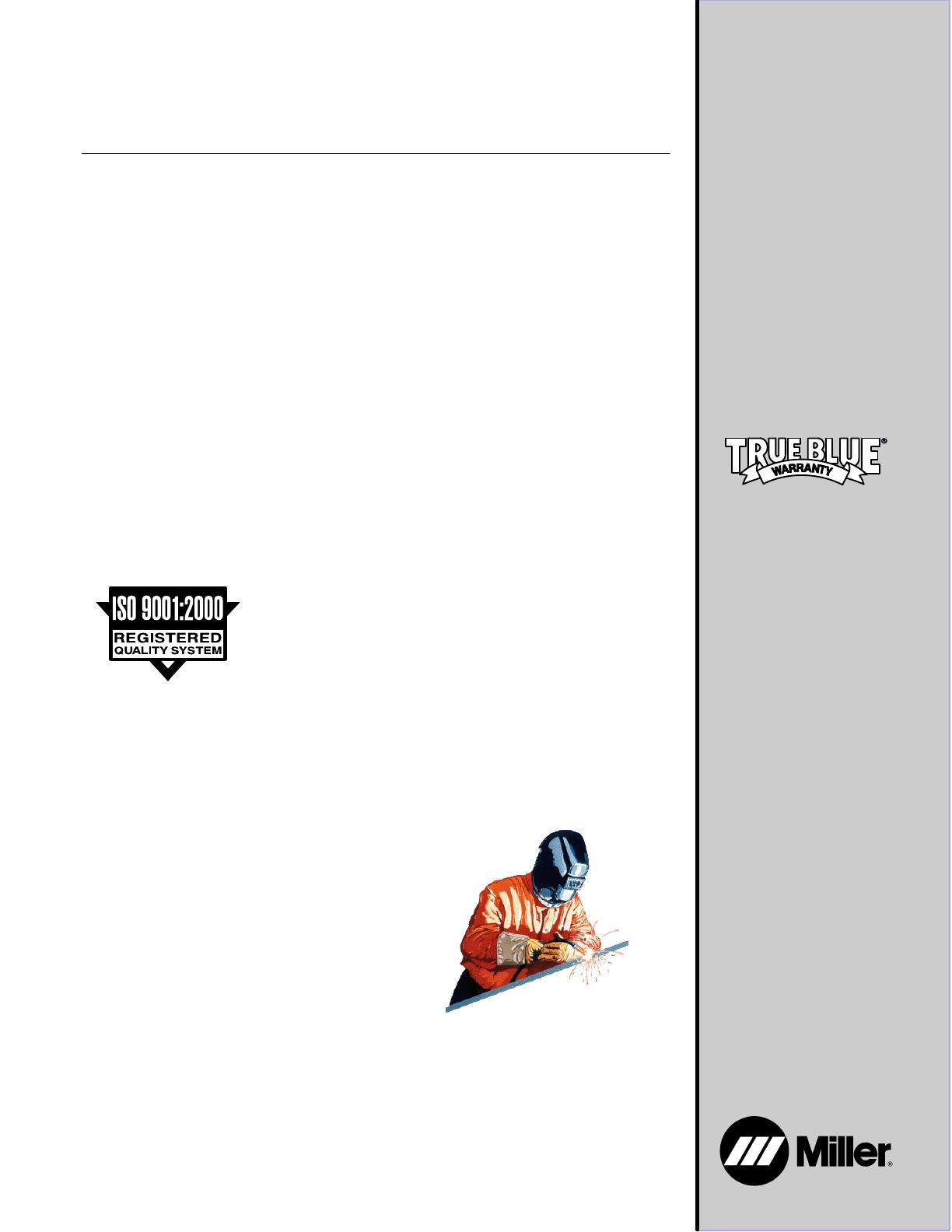
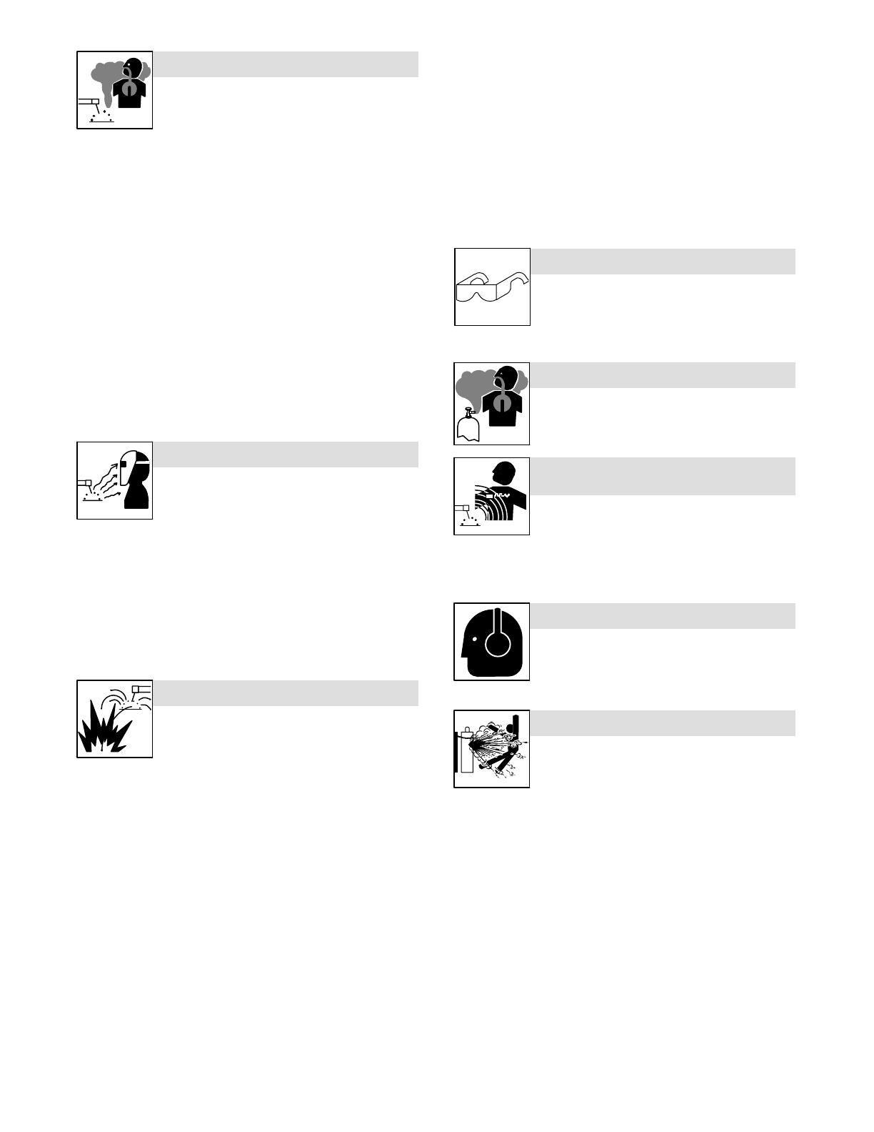
Welding produces fumes and gases. Breathing
these fumes and gases can be hazardous to your
health.
FUMES AND GASES can be hazardous.
Keep your head out of the fumes. Do not breathe the fumes.
If inside, ventilate the area and/or use local forced ventilation at the
arc to remove welding fumes and gases.
If ventilation is poor, wear an approved air-supplied respirator.
Read and understand the Material Safety Data Sheets (MSDSs)
and the manufacturer’s instructions for metals, consumables,
coatings, cleaners, and degreasers.
Work in a confined space only if it is well ventilated, or while
wearing an air-supplied respirator. Always have a trained watch-
person nearby. Welding fumes and gases can displace air and
lower the oxygen level causing injury or death. Be sure the breath-
ing air is safe.
Do not weld in locations near degreasing, cleaning, or spraying op-
erations. The heat and rays of the arc can react with vapors to form
highly toxic and irritating gases.
Do not weld on coated metals, such as galvanized, lead, or
cadmium plated steel, unless the coating is removed from the weld
area, the area is well ventilated, and while wearing an air-supplied
respirator. The coatings and any metals containing these elements
can give off toxic fumes if welded.
Arc rays from the welding process produce intense
visible and invisible (ultraviolet and infrared) rays
that can burn eyes and skin. Sparks fly off from the
weld.
ARC RAYS can burn eyes and skin.
Wear an approved welding helmet fitted with a proper shade of fil-
ter lenses to protect your face and eyes when welding or watching
(see ANSI Z49.1 and Z87.1 listed in Safety Standards).
Wear approved safety glasses with side shields under your
helmet.
Use protective screens or barriers to protect others from flash,
glare and sparks; warn others not to watch the arc.
Wear protective clothing made from durable, flame-resistant mate-
rial (leather, heavy cotton, or wool) and foot protection.
Welding on closed containers, such as tanks,
drums, or pipes, can cause them to blow up. Sparks
can fly off from the welding arc. The flying sparks, hot
workpiece, and hot equipment can cause fires and
burns. Accidental contact of electrode to metal objects can cause
sparks, explosion, overheating, or fire. Check and be sure the area is
safe before doing any welding.
WELDING can cause fire or explosion.
Remove all flammables within 35 ft (10.7 m) of the welding arc. If
this is not possible, tightly cover them with approved covers.
Do not weld where flying sparks can strike flammable material.
Protect yourself and others from flying sparks and hot metal.
Be alert that welding sparks and hot materials from welding can
easily go through small cracks and openings to adjacent areas.
Watch for fire, and keep a fire extinguisher nearby.
Be aware that welding on a ceiling, floor, bulkhead, or partition can
cause fire on the hidden side.
Do not weld on closed containers such as tanks, drums, or pipes,
unless they are properly prepared according to AWS F4.1 (see
Safety Standards).
Do not weld where the atmosphere may contain flammable dust,
gas, or liquid vapors (such as gasoline).
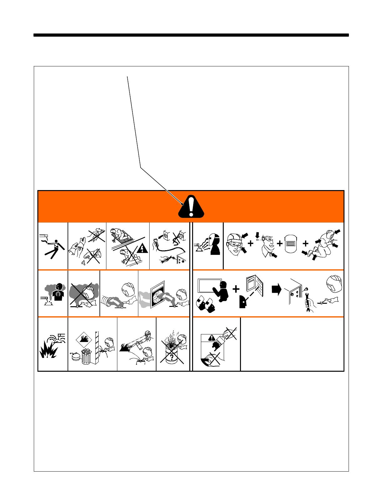
Connect work cable to the work as close to the welding area as
practical to prevent welding current from traveling long, possibly
unknown paths and causing electric shock, sparks, and fire
hazards.
Do not use welder to thaw frozen pipes.
Remove stick electrode from holder or cut off welding wire at
contact tip when not in use.
Wear oil-free protective garments such as leather gloves, heavy
shirt, cuffless trousers, high shoes, and a cap.
Remove any combustibles, such as a butane lighter or matches,
from your person before doing any welding.
After completion of work, inspect area to ensure it is free of sparks,
glowing embers, and flames.
Use only correct fuses or circuit breakers. Do not oversize or by-
pass them.
Follow requirements in OSHA 1910.252 (a) (2) (iv) and NFPA 51B
for hot work and have a fire watcher and extinguisher nearby.
FLYING METAL or DIRT can injure eyes.
Welding, chipping, wire brushing, and grinding
cause sparks and flying metal. As welds cool,
they can throw off slag.
Wear approved safety glasses with side
shields even under your welding helmet.
BUILDUP OF GAS can injure or kill.
Shut off shielding gas supply when not in use.
Always ventilate confined spaces or use
approved air-supplied respirator.
MAGNETIC FIELDS can affect Implanted
Medical Devices.
Wearers of Pacemakers and other Implanted
Medical Devices should keep away.
Implanted Medical Device wearers should consult their doctor
and the device manufacturer before going near arc welding, spot
welding, gouging, plasma arc cutting, or induction heating
operations.
NOISE can damage hearing.
Noise from some processes or equipment can
damage hearing.
Wear approved ear protection if noise level is
high.
Shielding gas cylinders contain gas under high
pressure. If damaged, a cylinder can explode. Since
gas cylinders are normally part of the welding
process, be sure to treat them carefully.
CYLINDERS can explode if damaged.
Protect compressed gas cylinders from excessive heat, mechani-
cal shocks, physical damage, slag, open flames, sparks, and arcs.
Install cylinders in an upright position by securing to a stationary
support or cylinder rack to prevent falling or tipping.
Keep cylinders away from any welding or other electrical circuits.
Never drape a welding torch over a gas cylinder.
Never allow a welding electrode to touch any cylinder.
Never weld on a pressurized cylinder explosion will result.
Use only correct shielding gas cylinders, regulators, hoses, and fit-
tings designed for the specific application; maintain them and
associated parts in good condition.
Turn face away from valve outlet when opening cylinder valve.
Keep protective cap in place over valve except when cylinder is in
use or connected for use.
Use the right equipment, correct procedures, and sufficient num-
ber of persons to lift and move cylinders.
Read and follow instructions on compressed gas cylinders,
associated equipment, and Compressed Gas Association (CGA)
publication P-1 listed in Safety Standards.
OM-216 869 Page 3
1-3. Additional Symbols For Installation, Operation, And Maintenance
FIRE OR EXPLOSION hazard.
Do not install or place unit on, over, or near
combustible surfaces.
Do not install unit near flammables.
Do not overload building wiring be sure power supply system is
properly sized, rated, and protected to handle this unit.
FALLING UNIT can cause injury.
Use lifting eye to lift unit only, NOT running
gear, gas cylinders, or any other accessories.
Use equipment of adequate capacity to lift and
support unit.
If using lift forks to move unit, be sure forks are
long enough to extend beyond opposite side of
unit.
OVERUSE can cause OVERHEATING
Allow cooling period; follow rated duty cycle.
Reduce current or reduce duty cycle before
starting to weld again.
Do not block or filter airflow to unit.
FLYING SPARKS can cause injury.
Wear a face shield to protect eyes and face.
Shape tungsten electrode only on grinder with
proper guards in a safe location wearing proper
face, hand, and body protection.
Sparks can cause fires — keep flammables away.
STATIC (ESD) can damage PC boards.
Put on grounded wrist strap BEFORE handling
boards or parts.
Use proper static-proof bags and boxes to
store, move, or ship PC boards.
MOVING PARTS can cause injury.
Keep away from moving parts.
Keep away from pinch points such as drive
rolls.
WELDING WIRE can cause injury.
Do not press gun trigger until instructed to do
so.
Do not point gun toward any part of the body,
other people, or any metal when threading
welding wire.
MOVING PARTS can cause injury.
Keep away from moving parts such as fans.
Keep all doors, panels, covers, and guards
closed and securely in place.
Have only qualified persons remove doors, panels, covers, or
guards for maintenance as necessary.
Reinstall doors, panels, covers, or guards when maintenance is
finished and before reconnecting input power.
READ INSTRUCTIONS.
Read Owners Manual before using or servic-
ing unit.
Use only genuine replacement parts from the
manufacturer.
H.F. RADIATION can cause interference.
High-frequency (H.F.) can interfere with radio
navigation, safety services, computers, and
communications equipment.
Have only qualified persons familiar with
electronic equipment perform this installation.
The user is responsible for having a qualified electrician prompt-
ly correct any interference problem resulting from the installa-
tion.
If notified by the FCC about interference, stop using the
equipment at once.
Have the installation regularly checked and maintained.
Keep high-frequency source doors and panels tightly shut, keep
spark gaps at correct setting, and use grounding and shielding to
minimize the possibility of interference.
ARC WELDING can cause interference.
Electromagnetic energy can interfere with
sensitive electronic equipment such as
computers and computer-driven equipment
such as robots.
Be sure all equipment in the welding area is
electromagnetically compatible.
To reduce possible interference, keep weld cables as short as
possible, close together, and down low, such as on the floor.
Locate welding operation 100 meters from any sensitive elec-
tronic equipment.
Be sure this welding machine is installed and grounded
according to this manual.
If interference still occurs, the user must take extra measures
such as moving the welding machine, using shielded cables,
using line filters, or shielding the work area.
OM-216 869 Page 4
1-4. California Proposition 65 Warnings
Welding or cutting equipment produces fumes or gases
which contain chemicals known to the State of California to
cause birth defects and, in some cases, cancer. (California
Health & Safety Code Section 25249.5 et seq.)
Battery posts, terminals and related accessories contain lead
and lead compounds, chemicals known to the State of
California to cause cancer and birth defects or other
reproductive harm. Wash hands after handling.
For Gasoline Engines:
Engine exhaust contains chemicals known to the State of
California to cause cancer, birth defects, or other reproduc-
tive harm.
For Diesel Engines:
Diesel engine exhaust and some of its constituents are
known to the State of California to cause cancer, birth
defects, and other reproductive harm.
1-5. Principal Safety Standards
Safety in Welding, Cutting, and Allied Processes, ANSI Standard Z49.1,
from Global Engineering Documents (phone: 1-877-413-5184, website:
www.global.ihs.com).
Recommended Safe Practices for the Preparation for Welding and Cut-
ting of Containers and Piping, American Welding Society Standard
AWS F4.1, from Global Engineering Documents (phone:
1-877-413-5184, website: www.global.ihs.com).
National Electrical Code, NFPA Standard 70, from National Fire Protec-
tion Association, P.O. Box 9101, Quincy, MA 02269-9101 (phone:
617-770-3000, website: www.nfpa.org and www. sparky.org).
Safe Handling of Compressed Gases in Cylinders, CGA Pamphlet P-1,
from Compressed Gas Association, 4221 Walney Road, 5th Floor,
Chantilly, VA 20151 (phone: 703-788-2700, website:www.cganet.com).
Code for Safety in Welding and Cutting, CSA Standard W117.2, from
Canadian Standards Association, Standards Sales, 5060 Mississauga,
Ontario, Canada L4W 5NS (phone: 800-463-6727 or in Toronto
416-747-4044, website: www.csa-international.org).
Safe Practice For Occupational And Educational Eye And Face Protec-
tion, ANSI Standard Z87.1, from American National Standards Institute,
25 West 43rd Street, New York, NY 10036–8002 (phone:
212-642-4900, website: www.ansi.org).
Standard for Fire Prevention During Welding, Cutting, and Other Hot
Work, NFPA Standard 51B, from National Fire Protection Association,
P.O. Box 9101, Quincy, MA 02269-9101 (phone: 617-770-3000, web-
site: www.nfpa.org.
OSHA, Occupational Safety and Health Standards for General Indus-
try, Title 29, Code of Federal Regulations (CFR), Part 1910, Subpart Q,
and Part 1926, Subpart J, from U.S. Government Printing Office, Super-
intendent of Documents, P.O. Box 371954, Pittsburgh, PA 15250-7954
(phone: 1-866-512-1800) (there are 10 Regional Offices—phone for
Region 5, Chicago, is 312-353-2220, website: www.osha.gov).
1-6. EMF Information
Considerations About Welding And The Effects Of Low Frequency
Electric And Magnetic Fields
Welding current, as it flows through welding cables, will cause electro-
magnetic fields. There has been and still is some concern about such
fields. However, after examining more than 500 studies spanning 17
years of research, a special blue ribbon committee of the National
Research Council concluded that: “The body of evidence, in the
committee’s judgment, has not demonstrated that exposure to power-
frequency electric and magnetic fields is a human-health hazard.”
However, studies are still going forth and evidence continues to be
examined. Until the final conclusions of the research are reached, you
may wish to minimize your exposure to electromagnetic fields when
welding or cutting.
To reduce magnetic fields in the workplace, use the following
procedures:
1. Keep cables close together by twisting or taping them, or using a
cable cover.
2. Arrange cables to one side and away from the operator.
3. Do not coil or drape cables around your body.
4. Keep welding power source and cables as far away from opera-
tor as practical.
5. Connect work clamp to workpiece as close to the weld as possi-
ble.
About Implanted Medical Devices:
Implanted Medical Device wearers should consult their doctor and the
device manufacturer before performing or going near arc welding, spot
welding, gouging, plasma arc cutting, or induction heating operations.
If cleared by your doctor, then following the above procedures is recom-
mended.
OM-216 869 Page 9
2-5. Principales normes de sécuri
Safety in Welding, Cutting, and Allied Processes, ANSI Standard Z49.1,
de Global Engineering Documents (téléphone : 1-877-413-5184, site
Internet : www.global.ihs.com).
Recommended Safe Practices for the Preparation for Welding and Cut-
ting of Containers and Piping, American Welding Society Standard
AWS F4.1 de Global Engineering Documents (téléphone :
1-877-413-5184, site Internet : www.global.ihs.com).
National Electrical Code, NFPA Standard 70, de National Fire Protec-
tion Association, P.O. Box 9101, Quincy, MA 02269-9101 (téléphone :
617-770-3000, site Internet : www.nfpa.org).
Safe Handling of Compressed Gases in Cylinders, CGA Pamphlet P-1,
de Compressed Gas Association, 4221 Walney Road, 5th Floor, Chan-
tilly, VA 20151 (téléphone : 703-788-2700, site Internet :
www.cganet.com).
Code for Safety in Welding and Cutting, CSA Standard W117.2, de
Canadian Standards Association, 5060 Mississauga, Ontario, Canada
L4W 5NS (téléphone : 800-463-6727 ou à Toronto 416-747-4044, site
Internet : www.csa-international.org).
Safe Practice For Occupational And Educational Eye And Face Protec-
tion, ANSI Standard Z87.1, de American National Standards Institute,
11 West 43rd Street, New York, NY 10036-8002 (téléphone :
212-642-4900, site Internet : www.ansi.org).
Standard for Fire Prevention During Welding, Cutting, and Other Hot
Work, NFPA Standard 51B, de National Fire Protection Association,
P.O. Box 9101, Quincy, MA 02269-9101 (téléphone : 617-770-3000,
site Internet : www.nfpa.org).
OSHA, Occupational Safety and Health Standards for General Indus-
try, Title 29, Code of Federal Regulations (CFR), Part 1910, Subpart Q,
and Part 1926, Subpart J, de U.S. Government Printing Office, Superin-
tendent of Documents, P.O. Box 371954, Pittsburgh, PA 15250-7954
(téléphone : 1-866-512-1800) (il y a 10 bureaux régionaux−−le télépho-
ne de la région 5, Chicago, est 312-353-2220, site Internet :
www.osha.gov).
2-6. Information EMF
Considérations sur le soudage et les effets de basse fréquence et des
champs magnétiques et électriques.
Le courant de soudage, pendant son passage dans les câbles de sou-
dage, causera des champs électromagnétiques. Il y a eu et il y a encore
un certain souci à propos de tels champs. Cependant, après avoir exa-
miné plus de 500 études qui ont été faites pendant une période de
recherche de 17 ans, un comité spécial ruban bleu du National
Research Council a conclu : « L’accumulation de preuves, suivant le
jugement du comité, n’a pas démontré que l’exposition aux champs
magnétiques et champs électriques à haute fréquence représente un
risque à la santé humaine ». Toutefois, des études sont toujours en
cours et les preuves continuent à être examinées. En attendant que les
conclusions finales de la recherche soient établies, il vous serait
souhaitable de réduire votre exposition aux champs électromagnéti-
ques pendant le soudage ou le coupage.
Pour réduire les champs magnétiques sur le poste de travail, appliquer
les procédures suivantes :
1. Garder les câbles ensemble, les torsader, les scotcher, ou les
recouvrir d’une housse.
2. Disposer les câbles d’un côté et à distance de l’opérateur.
3. Ne pas courber pas et ne pas entourer pas les câbles autour de
votre corps.
4. Garder le poste de soudage et les câbles le plus loin possible de
vous.
5. Connecter la pince sur la pièce aussi près que possible de la
soudure.
En ce qui concerne les implants médicaux :
Les porteurs d’implants doivent d’abord consulter leur médecin avant
de s’approcher des opérations de soudage à l’arc, de soudage par
points, de gougeage, du coupage plasma ou de chauffage par induc-
tion. Si le médecin approuve, il est recommandé de suivre les
procédures précédentes.
OM-216 869 Page 11
SECTION 3 DEFINITIONS (CE Models Only)
3-1. Warning Label Definitions
Warning! Watch Out! There are possible
hazards as shown by the symbols.
1 Electric shock from welding electrode
or wiring can kill.
1.1 Wear dry insulating gloves. Do not
touch electrode with bare hand. Do
not wear wet or damaged gloves.
1.2 Protect yourself from electric shock by
insulating yourself from work and
ground.
1.3 Disconnect input plug or power before
working on machine.
2 Breathing welding fumes can be
hazardous to your health.
2.1 Keep your head out of the fumes.
2.2 Use forced ventilation or local exhaust
to remove the fumes.
2.3 Use ventilating fan to remove fumes.
3 Welding sparks can cause explosion
or fire.
3.1 Keep flammables away from welding.
Do not weld near flammables.
3.2 Welding sparks can cause fires. Have
a fire extinguisher nearby, and have a
watchperson ready to use it.
3.3 Do not weld on drums or any closed
containers.
4 Arc rays can burn eyes and injure
skin.
4.1 Wear hat and safety glasses. Use ear
protection and button shirt collar. Use
welding helmet with correct shade of
filter. Wear complete body protection.
5 Become trained and read the
instructions before working on the
machine or welding.
6 Do not remove or paint over (cover)
the label.
1 1.1 1.2 1.3
2 2.1 2.2 2.3
3 3.1 3.2 3.3
4 4.1
5
6
OM-216 869 Page 12
Warning! Watch Out! There are
possible hazards as shown by the
symbols.
1 Electric shock from wiring can
kill.
2 Disconnect input plug or
power before working on
machine.
3 Hazardous voltage remains
on input capacitors after
power is turned off. Do not
touch fully charged
capacitors.
4 Always wait 5 minutes after
power is turned off before
working on unit, OR
5 Check input capacitor voltage,
and be sure it is near 0 before
touching any parts.
6 When power is applied failed
parts can explode or cause
other parts to explode.
7 Flying pieces of parts can
cause injury. Always wear a
face shield when servicing
unit.
8 Always wear long sleeves and
button your collar when
servicing unit.
9 After taking proper
precautions as shown,
connect power to unit.
1
2
3
45
6 7
8
9
5
1
1 Warning! Watch Out! There
are possible hazards as
shown by the symbols.
2 Electric shock from wiring can
kill.
3 Read the Owners Manual
before working on this
machine.
4 Disconnect input plug or
power before working on
machine.
5 Become trained and read the
instructions before working on
the machine or welding.
2
4
3
OM-216 869 Page 13
S-180 663
1 2 3 4 5
6
7 8 9
1 Warning! Watch Out! There are
possible hazards as shown by the
symbols.
2 Electric shock from wiring can kill.
3 Disconnect input plug or power before
working on machine.
4 Moving parts, such as fans, can cut
fingers and hands and cause injury.
Keep away from moving parts.
5 Wear safety glasses with side shields.
6 Read the Owners Manual before
working on this machine.
7 Read the labels on the welding power
source, wire feeder, or other major
equipment for welding safety
information.
8 Recycle or dispose of used coolant in
an environmentally safe way.
9 Do not remove or paint over (cover)
the label.
4/96
S-178 910
=
043 810 (HF)
043 809 (AL)
100 h. std.
21 3
6
4
7
5
1 Warning! Watch Out! There are
possible hazards as shown by the
symbols.
2 Disconnect input plug or power before
working on machine.
3 Wear safety glasses with side shields.
4 Plugged filter or hoses cause
overheating and damage.
5 Read Owners Manual.
6 Check and clean filter every 100
hours; also check condition of hoses.
7 Use Low Conductivity Coolant No. 043
810 for High-Frequency assisted or
Gas Tungsten Arc Welding
applications. Use Aluminum Protecting
Coolant No. 043 809 where coolant
contacts aluminum parts or for Gas
Metal Arc Welding applications or
where High Frequency is not used.
OM-216 869 Page 14
3-2. Manufacturers Rating Labels For Dynasty 350 Models
For label location
see Section 4-4.
Manufacture’s Rating Label For
Dynasty 350 Non-CE Models
Manufacture’s Rating Label
For Dynasty 350 CE Models
OM-216 869 Page 15
3-3. Manufacturers Rating Labels For Maxstar 350 Models
For label location
see Section 4-4.
Manufacture’s Rating Label For
Maxstar 350 Non-CE Models
Manufacture’s Rating Label
For Maxstar 350 CE Models
OM-216 869 Page 16
3-4. Manufacturers Rating Labels For Dynasty 700 Models
For label location
see Section 4-4.
Manufacture’s Rating Label For
Dynasty 700 Non-CE Models
Manufacture’s Rating Label
Dynasty 700 Models
OM-216 869 Page 17
3-5. Manufacturers Rating Labels For Maxstar 700 Models
For label location
see Section 4-4.
Manufacture’s Rating Label For
Maxstar 700 Non-CE Models
Manufacture’s Rating Label
For Maxstar 700 CE Models
  • Page 1 1
  • Page 2 2
  • Page 3 3
  • Page 4 4
  • Page 5 5
  • Page 6 6
  • Page 7 7
  • Page 8 8
  • Page 9 9
  • Page 10 10
  • Page 11 11
  • Page 12 12
  • Page 13 13
  • Page 14 14
  • Page 15 15
  • Page 16 16
  • Page 17 17
  • Page 18 18
  • Page 19 19
  • Page 20 20
  • Page 21 21
  • Page 22 22
  • Page 23 23
  • Page 24 24
  • Page 25 25
  • Page 26 26
  • Page 27 27
  • Page 28 28
  • Page 29 29
  • Page 30 30
  • Page 31 31
  • Page 32 32
  • Page 33 33
  • Page 34 34
  • Page 35 35
  • Page 36 36
  • Page 37 37
  • Page 38 38
  • Page 39 39
  • Page 40 40
  • Page 41 41
  • Page 42 42
  • Page 43 43
  • Page 44 44
  • Page 45 45
  • Page 46 46
  • Page 47 47
  • Page 48 48
  • Page 49 49
  • Page 50 50
  • Page 51 51
  • Page 52 52
  • Page 53 53
  • Page 54 54
  • Page 55 55
  • Page 56 56
  • Page 57 57
  • Page 58 58
  • Page 59 59
  • Page 60 60
  • Page 61 61
  • Page 62 62
  • Page 63 63
  • Page 64 64
  • Page 65 65
  • Page 66 66
  • Page 67 67
  • Page 68 68
  • Page 69 69
  • Page 70 70
  • Page 71 71
  • Page 72 72
  • Page 73 73
  • Page 74 74
  • Page 75 75
  • Page 76 76
  • Page 77 77
  • Page 78 78
  • Page 79 79
  • Page 80 80
  • Page 81 81
  • Page 82 82
  • Page 83 83
  • Page 84 84
  • Page 85 85
  • Page 86 86
  • Page 87 87
  • Page 88 88
  • Page 89 89
  • Page 90 90
  • Page 91 91
  • Page 92 92
  • Page 93 93
  • Page 94 94
  • Page 95 95
  • Page 96 96
  • Page 97 97
  • Page 98 98
  • Page 99 99
  • Page 100 100
  • Page 101 101
  • Page 102 102
  • Page 103 103
  • Page 104 104
  • Page 105 105
  • Page 106 106
  • Page 107 107
  • Page 108 108
  • Page 109 109
  • Page 110 110
  • Page 111 111
  • Page 112 112
  • Page 113 113
  • Page 114 114
  • Page 115 115
  • Page 116 116
  • Page 117 117
  • Page 118 118
  • Page 119 119
  • Page 120 120
  • Page 121 121
  • Page 122 122
  • Page 123 123
  • Page 124 124
  • Page 125 125
  • Page 126 126
  • Page 127 127
  • Page 128 128
  • Page 129 129
  • Page 130 130
  • Page 131 131
  • Page 132 132
  • Page 133 133
  • Page 134 134

Ask a question and I''ll find the answer in the document

Finding information in a document is now easier with AI