WELL-McLAIN AquaBalance Series 2 User guide

Type
User guide
Part number 550-100-316/0419
LEGEND
1 — Domestic Hot Water temperature setpoint
decreasing button
2 — Domestic Hot Water temperature setpoint
increasing button
3 — Central Heating water temperature setpoint
decreasing button
4 — Central Heating water temperature setpoint
increasing button
5 — LCD Display
6 — Reset / OTC button
7 — Economy / Comfort On / Off Power button
8 — Domestic Hot Water symbol
9 — Domestic Hot Water mode operation
10 — Multi-function indication (Flashing during heat
exchanger protection)
11 — Economy symbol
12 — Central Heating mode operation
13 — Central Heating symbol
14 — Burner on and actual load indication
(Flashing during flame current supervision)
15 — Service tool connection
16Temperature-Pressure gauge
Series 1 & 2
Aqua Balance
®
AquaBalance
®
CONTROL MODULE QUICK START GUIDE
Part number 550-100-316/04192
Software version
Air purge
Push On/Off button
During the first 5 seconds, the display shows the software version of the control module.
For the next 300 seconds, the display shows FH that identifies the Air purge function.
When the FH disappears, the boiler is ready to function automatically whenever the external controls are calling for heat.
System start
1
Push
eco / comfort
/ Power button; to start boiler
2
NOTE: If an A-16 error code is displayed (Central Heating Only boiler) when unit is powered up, the outdoor
sensor is not installed. Install outdoor sensor and push the reset button to reset error code. A faulty outdoor
sensor will give an “F-39” error code.
The outdoor sensor must be installed unless specifically exempted in the Energy Act statement on page 102 of
AquaBalance boiler manual.
3
04 shows on the display” (control software version)
4
FH shows on the display”
(Blower /inducer operating in purge mode of combustion chamber and venting for 5 minutes).
5
With no call for heat” (current boiler water temperature will be shown in degrees F).
6
To Change “Central Heating water temperature set-point” (from 68 F to 190 degrees F) use the bottom set of “+” or “–”
keys to raise or lower the set point temperature.
7
To change “Domestic water temperature set-point” ( from 104 F to 131 degrees F ) NOTE: Insure that operating temperature is
a safe set-point temperature. Use the top set of “+” or “–” keys to raise or lower the set point.
8
To change Venting material” - see page 7 and boiler manual.
Power On mode
AquaBalance
®
CONTROL MODULE QUICK START GUIDE
Part number 550-100-316/0419
3
When the boiler is turned off with eco”/power button, the con-
trol module is still powered, heating operation is disabled and
the display is off, however the frost protection will still be active.
To turn boiler on again, press the on/off button
(hold for 5 seconds)
The boiler is ready to function automatically whenever the external controls are calling for heat.
On/Off button
Setting Heating Temperature
To set the system Heating temperature, use the CH buttons, “-” to reduce water setpoint “+” to increase water setpoint.
It can be set from a minimum of 68° F to a maximum of 190° F.
The Central Heating heat demand (generated by the Room Thermostat) is indicated by the flashing of the Hot Air symbol over
the radiator (Items 12 and 13 - pages 1 or 4). The display indicates the actual Central Heating water temperature (Item 10 -
pages 1 or 4) and when the required set point temperature is reached d2 will be displayed.
AquaBalance
®
CONTROL MODULE QUICK START GUIDE
Part number 550-100-316/04194
Setting Domestic Hot Water Temperature
To set the Domestic hot water temperature, use the DHW buttons, “-” to reduce water setpoint “+” to increase water setpoint.
It can be set from a minimum of 104° F to a maximum of 131° F.
The Domestic Hot Water heat demand (generated by the DHW flow sensor) is indicated by the flashing of the Hot Water sym-
bol under the tap (Items 8 and 9 – see below). The display indicates the actual Domestic Hot Water temperature (Item 10 – see
below) and after Hot set point temperature is reached d1 will be displayed.
The minimum flow rate to start a DHW call is 0.4 GPM and the flow rate that shuts it off is 0.3 GPM.
NOTE: Combi boilers recommended to be in comfort” mode.
See page 53 of the boiler manual for eco/comfort selection options.
Outdoor Reset Control
1. When the external outdoor sensor is attached to the boiler, the system can work in Outside Temperature Compensation mode.
In OTC mode the temperature of the heating system is controlled according to the external climate conditions, this will insure
a high degree of comfort and Energy saving all year round.
2. By using the CH buttons (Items 3 and 4) it is possible to set the maximum system water temperature for the installation.
AquaBalance
®
CONTROL MODULE QUICK START GUIDE
Part number 550-100-316/0419
5
OTC setting
1. To enter the OTC - reset mode, press reset button for 5 seconds, takes you to Curve menu.
2. The display shows CU flashing which allows you to adjust the Curves value, using the DHW + or – buttons, (items 1 and 2
– above). Select from 1 to 10, in accordance with the charts, Figures 2 or 3, on page 6, or “0”, which means no OTC mode. By
pressing the CH push buttons together (Items 3 and 4 - below), the display shows 0F flashing; to set Offset, use the DHW
push buttons (Items 1 and 2 - above). It can be 68 to 104, in accordance with the chart Figure 2 or Figure 3, page 6.
In the case of an outdoor sensor failure, the control will continue to operate the boiler, but without the use of the
Compensation Curves, and an error message will flash on the display (Fault 39 – see Troubleshooting section in boiler manual).
Upon replacement of the defective sensor the boiler will resume the use of Compensation Curves.
OTC Exempt mode
By pressing the DHW+ and eco buttons together for 10 seconds, it is possible to enter the OTC Exempt menu. The display starts
showing the value of the parameter OTC Exempt (See parameter Number 163, page 89 in boiler manual) flashing. By means of
the CH - push button it is possible to change value.
(Selecting 0 - allows you to Select the Compensation curve for your individual home heating needs). By pressing DHW+ and
eco buttons together for 10 seconds, it is possible to leave the OTC Exempt Menu. If no action has been taken, the control auto-
matically leaves this mode after 2 minutes.
- 0 = installation non exempt from outside sensor connection;
- 1 = installation exempt from outside sensor connection;
CH
“reset” button
3 4
3. Switch to OF (Offset mode) by pressing the CH + or – buttons (Items 3 and 4 - above). The display shows OF flashing
4. The default valve for the Curve is 0, meaning the at no compensation is selected as default.
5. The default valve for the Offset is 86.
6. To exit the OTC mode, press reset button for 5 seconds.
DHW
“reset” for OTC
1 2
eco
AquaBalance
®
CONTROL MODULE QUICK START GUIDE
Part number 550-100-316/04196
Figure 1 Compensation curves reference
Figure 2 Compensation parallel offset curves – Typical low temperature radiant application such as in-floor tubing.
Figure 3 Compensation parallel offset curves –
Typical Copper fin tube /cast iron baseboard radiation.
OFFSET = 68
Starting temperature
Compensation curves – Curve numbers below refer to Figures 1, 2, and 3 – below.
• Curve number 1 is for a high efficiency home with very low heat losses.
• Curve number 6 is for an average home heat losses.
• Curve number 10 is for a home with high heat losses.
68
86
104
122
140
158
176
194
-42814202632384450566268
BOILER FLOW TEMPERATURE (°F)
OUTSIDE AIR TEMPERATURE (°F)
OTC CURVES
1
2
3
4
5
6
78910
OFFSET = 104
AquaBalance
®
CONTROL MODULE QUICK START GUIDE
Part number 550-100-316/0419
7
AquaBalance Common Control Programming / Error
Codes & Functions Used
1. Outdoor sensor A16 (Central Heating Only boiler, should not appear on Combi boilers)
• When unit is powered up and no outdoor sensor is connected A16 error code will flash,
• Pushreset button for 1.5 seconds, error code will clear.
2. Venting Material Change b22 (boiler is defaulted for PVC vent material)
If other vent material is used, you program that material via the control board.
Control selection for vent material
To insure proper boiler operation, the boiler control programmed default is for PVC venting material. You MUST program the
boiler control for any other venting material that you installed other than PVC, in order to improve operational efficiency.
Refer to “Control Module Quick Start Guide page 2, to first power up the boiler.
To access the configuration menu:
1. Press the DHW + and DHW – buttons together for 10 seconds.
2. At the end of the ten seconds, the display will show the message “b01”; Use the CH buttons (+ or –) to scroll through
parameters. b01, then scroll up tob22”.
DHW
1. Push DHW buttons + & - together for 10 seconds
2. Press Heating buttons + & - to
scroll up or down the parameter
numbers
You MUST exit out of ALL of the programming modes when
you have nished your vent selection.
(see next page)
AquaBalance
®
CONTROL MODULE QUICK START GUIDE
PVC solid core, .......................................... Select: “1” (Default)
CPVC only, ................................................ Select: “2”
Polypropylene and AL29-4C, ................... Select: “0”
1. Press the heating buttons (+ or -) to scroll up the list of parameters in increasing or decreasing order to parameter b22
Venting Material selection.
2. Press the DHW buttons (+ or -) to view or modify the value of a parameter: press the “DHW +” and “DHW -” buttons
together for 10 seconds, saves selection.
For example: CPVC, Polypropylene, or AL29-4C stainless steel.
DHW
3. Use the DHW + or – buttons to modify the parameter value
Exiting the “User interface setting” menu. Press the “DHW +”
and “DHW -” buttons together for 10 seconds; or switch the
power to the unit o and then on again; or wait for automatic
exiting which occurs aer two (2) minutes
Part number 550-100-316/04198
AquaBalance
®
CONTROL MODULE QUICK START GUIDE
3. Boiler “Test Mode Operation
• UsedtocheckcombustionparameterswhencheckingNaturalGasfuelcombustionandwhenadjustingcombustionparam-
eters for LP fuel conversion.
• Pages63and64intheboilermanual.
• If you hear water gurgling, sloshing and / or air in the combustion chamber area (heat exchanger
tubing) the boiler needs to be purged of that air to operate properly.
• Anotherindicationofairintheheatexchangerwouldbetheboilerwillnotstayinthistestmodeonhighre.(thiscanalso
happen if the boiler is not piped in the correct size, wrong pump or speed selected (Internal circulator switch set to High)
and not piped “primary-secondary” causing flow issues).
• The boiler must be completely piped-up with all zones in operation to be able to handle the
boiler heating load of maximum fire operation.
Test Mode Operation
Proceed to put the boiler into operation as follows:
1. To operate the boiler in test mode, press the CH “-” and “+” keys together for 5 seconds (See below) to activate the TEST
mode.
2. The boiler lights at the maximum heating 100% rate displayed on the display.
3. The high fire (large) flame symbol will be displayed once the boiler has lit.
4. Use DHW “-” button to drop firing rate to low fire.
5. To exit the TEST mode, press the CH keys (Items 3 and 4 - front page or page 5) together for 5 seconds, or leave the boiler to
automatically switch off after 15 minutes or stopping DHW flow.
6. This TEST procedure is used to check/adjust combustion CO and CO
2
per specifications Figure 84, page 63 and Figure 87, page 64
in the AquaBalance boiler manual.
Part number 550-100-316/0419
9
AquaBalance
®
CONTROL MODULE QUICK START GUIDE
Part number 550-100-316/041910
4. Fuel Conversion to LP Fuel
• Withboilerinstandbymode,presstheDHW+&-buttonstogether for 10 seconds……….the display will flash b01
• Press the DHW + button….. to select 01 value, which is LP fuel.
(Factory default 0 is Natural gas)
• LP fuel conversion steps must be completed per this instruction and the boiler manual.
New replacement control boards out of the box are fac-
tory programmed for a 120-N-C (combi boiler) and specic
parameters MUST be set for any other boiler model that the
control board is installed in. (See chart below).
• Press the Heating + button to scroll to parameters b01 to b12 and verify the setting per the “Default Control Board”
parameter listed below and make appropriate changes if required. NOTE: specific boiler model has particular operational
parameters per Figure 102 in the appropriate boiler manual or Table 1 for Series 1 or Table 2 for Series 2.
• PresstheDHW+or–buttonsto“modifythevalue.
• PresstheDHW+and–buttonstogetherfor10secondsto exit the programming mode.
Boiler
Model
“b01” “b02” “b04” “b05” “b06” “b10” “b12” “P01” “P02” “P04”
Gas type
Boiler
type
Fan Max.
Freq. in DHW
Fan Max.
Freq. in CH
Fan Min.
Freq. in CH
S/W mode
selection button
Var. Out
Relay
Ignition
level
CH Slope
(F/min)
CH
Off Time
WMB-80-N-C
0=Nat. gas 3 155 155 40 1 0 80 6 2
WMB-120-N-C
0=Nat. gas 3 200 200 40 1 0 60 6 2
WMB-155-N-C
0=Nat. gas 3 205 205 39 1 7 60 6 2
WMB-80-N-H
0=Nat. gas 2 155 155 40 1 0 80 6 2
WMB-120-N-H
0=Nat. gas 2 200 200 40 1 0 60 6 2
WMB-155-N-H
0=Nat. gas 2 205 205 39 1 0 60 6 2
WMB-80-LP-C
1=LPG 3 145 145 40 1 0 80 6 2
WMB-120-LP-C
1=LPG 3 185 185 40 1 0 60 6 2
WMB-155-LP-C
1=LPG 3 200 200 40 1 7 60 6 2
WMB-80-LP-H
1=LPG 2 145 145 40 1 0 80 6 2
WMB-120-LP-H
1=LPG 2 185 185 40 1 0 60 6 2
WMB-155-LP-H
1=LPG 2 200 200 40 1 0 60 6 2
Table 1 Default Control Board “Transparent Parameters” for AquaBalance
®
Series 1 boilers.
AquaBalance
®
CONTROL MODULE QUICK START GUIDE
Part number 550-100-316/0419
11
5. P01 and P02 Control Parameters Fuel
• P01 parameter (ignition level) as well needs to be changed upon the installation of a new control board. To access the tS
(Transparent Parameters section) follow the steps below.
• P02 parameter (Central Heating Slope) in some cases is too aggressive depending on particular installations, and can be
“user / field adjusted” to 6….a less aggressive temperature ramping to boiler water set-point”.
1. To access the “Transparent Parameters” menu. Press the reset button for 20 seconds.
2. At the end of 20 seconds the display will show the message tS”.
3. Press the “reset button for 1 second.
4. The display will show the message P01”.
5. Press the Heating buttons to scroll the list of parameters increasing and decreasing order. Press DHW buttons to view or
modify the value of a parameter: the modification will be automatically saved.
6. Set the parameter value for P01 and “P02 to value show in Figure 102 above, according to your boiler model.
7. Exiting the “Transparent Parameter” menu. Press the reset button for 20 seconds; or wait for automatic exiting which
occurs after fifteen (15) minutes.
Table 2 Default Control Board “Transparent Parameters” for AquaBalance
®
Series 2 boilers.
Boiler
Model
“b01” “b02” “b04” “b05” “b06” “b10” “b12”
“b22”
“P01” “P02” “P04”
Gas
type
Boiler
type
Fan
Max. Freq.
in DHW
Fan
Max. Freq.
in CH
Fan
Min. Freq.
in CH
S/W mode
selection
button
Var. Out
Relay
Vent
material
Ignition
level
CH Slope
(F/min)
CH
Off Time
AB-80-N-C
0=Nat. gas
3 155 155 35 1 0 1 80 6 2
AB-120-N-C
0=Nat. gas
3 200 200 40 1 0 1 60 6 2
AB-155-N-C
0=Nat. gas
3 210 210 39 1 7 1 50 6 2
AB-80-N-H
0=Nat. gas
2 155 155 35 1 0 1 80 6 2
AB-120-N-H
0=Nat. gas
2 200 200 40 1 0 1 60 6 2
AB-155-N-H
0=Nat. gas
2 210 210 39 1 0 1 50 6 2
AB-80-LP-C
1=LPG
3 145 145 35 1 0 1 80 6 2
AB-120-LP-C
1=LPG
3 185 185 40 1 0 1 60 6 2
AB-155-LP-C
1=LPG
3 220 220 40 1 7 1 50 6 2
AB-80-LP-H
1=LPG
2 145 145 35 1 0 1 80 6 2
AB-120-LP-H
1=LPG
2 185 185 40 1 0 1 60 6 2
AB-155-LP-H
1=LPG
2 220 220 40 1 0 1 50 6 2
AquaBalance
®
CONTROL MODULE QUICK START GUIDE
Part number 550-100-316/041912
6. Boiler Operation “In Safe Mode”
• Allboilershaveaprotectionmode,wherethecontrols/sensorslookatueexhausttemperaturestoinsurethattheyare
within correct safe operational values. When they exceed that temperature / value the boiler ramps down the firing rate to
low fire and approximately 130 – 140 degrees central heating boiler water temperature. The boiler will stay in that range
until the call for heat by the T Stat is removed momentarily or the boiler is powered by the plug.
• Seethefollowingonhowtoidentifythat“safemodeoperationandcorrections.
Key Questions to ask …when the boiler “seems to be in a low ring rate
(Will not ramp up to high ring rate)
• Ventinglengthandsize,permanual……didtheyuseLONG sweep elbows ?
isisVERYimportant!
• Pipingiscritical…AB-155CmustbeFULL1inchNOPEXforprimaryloopunlessthettingareFULLportsize.
• CheckCHtemperaturesettingandconsiderreducingitto180orlower.(whatisthesetpoint?)
• Changeparameter“P02” to 6 (boiler ramp slope) ……was factory set to 11 degrees
(which may be too high on some installs).
• Besureinternalpumpswitchonthecombiissetforhighspeed.
• ChangeMaxexhausttemperatureparameter“b16”to200(degreesF).
• ChangePVCmaximumtemperatureparameter“b23”to190(degreesF).
To test that this is the problem…..disconnect the T-stat call for heat for 30 seconds.
en restart call for HEAT by the thermostat.
If the boiler now ramps up to set point temperature….refer to above questions and corrections. (this conrms that the boiler
waslockedintothe“safetydownring”mode).
• Using an aggressive boiler ramp of 11 (parameter “P02”) and some piping systems as well as user boiler set point of
190 degree F, the boiler shoots past that set point and activates the “Safe Mode” protection.
AquaBalance
®
CONTROL MODULE QUICK START GUIDE
Part number 550-100-316/0419
13
7.
What is D1, D2 and D3 ?
• D1….the boiler is / has finished the call for Domestic Water heating, and is in the transition to either standby mode or
central heating mode.
• D2….the boiler has reached the required water set point, and the firing has stopped / with a call for Central Heating still
applied by the T-Stat to the boiler. Pumps will continue to operate and the boiler is monitoring the two internal water
sensors (return & discharge) waiting for a water “Delta-T” to return…at that time the boiler will re-fire if need be
• D3….the boiler has made 3 tries for ignition and has failed to ignite. A re-trial ignition cycle / delay is in effect for 3 more
tries to ignite.
8. Common Boiler Error Codes
Best methods to evaluate the A01 error code.
• Reset error code by pushing reset button on control module for 1.5 seconds.
• Newinstall,havecontractorverifythegassupplyispurged.
A01….”No burner ignition
Probable causes/solutions
• No gas (new install, gas line not purged)
• Ignition / detection electrode fault
• Faulty gas valve
• Insufficient gas supply pressure (Specs: 3.5 to 11 w.c.)
• Dirty heat exchanger/overdue for cleaning and maintenance.
• Condensatetrapblocked(ordoubletrapped)DONOTloopcondensatedrainhose.
Parameter Description
D1
After cycle of Domestic water mode, D1 will be displayed.
D2
When required boiler water set - point is reached D2 will be displayed.
D3
After an attempt for ignition, re-trial ignition delay is in effect (D3 is displayed).
• Check for proper fuel supply.
• Removeandcheckignitorforpropergap,5/32”,replaceifdisgured,checkcombustionsettingNaturalgasorLP.
• Insure condensate is draining properly.
• Insure venting size and length are correct and unobstructed.
AquaBalance
®
CONTROL MODULE QUICK START GUIDE
Part number 550-100-316/041914
Inlet test port
To assist in LPG conversion, follow the steps below:
Natural gas to LPG conversion
• WithboilerfuelsupplyOFF,followtheinstallationinstructionssuppliedwiththeLPGconversionventuri.
• Withboilerpoweredoff.
• InstallrequiredLPGconversionventurispecicforyourboilermodel.
• Withboilerin“standbymode”nocallsforcentralheatingordomesticwaterheating.
• Insureboilerfuelparameterb01 is changed to”1” for LPG fuel, Figure 102, pages 10 or 11.
• AdjustgasvalveHIGHFIREscrewonrightwithAllenwrenchturnCounter-Clockwise1-1/8turns.
• AdjustgasvalveLOWFIREscrewonleft(removecovercapwithsuppliedTorxwrench),thenturnthescrew
Counter-Clock wise ¼ turn.
• Replacethegasvalveadjustmentcovercapandtighten.
• ThiswilladjustyourcombustionforLPGtobeabletoruntheboilerintheHIGH&LOWretestmodetofurther
adjust your combustion with your combustion analyzer. See Section 28, “Setting the Air / Gas Ratio, pages 63-64
in the boiler manual, and follow those instructions.
Use a T10 Torx wrench to slightly open
theTorxset-screw,slidemanometerhose
over the set screw housing to read gas
pressurewhiletheboilerisring.Check
gaspressure,andsecurelytightenTorx
set screw aer testing.
(T10Torx“key”issuppliedwiththeboiler)
AquaBalance
®
CONTROL MODULE QUICK START GUIDE
Part number 550-100-316/0419
15
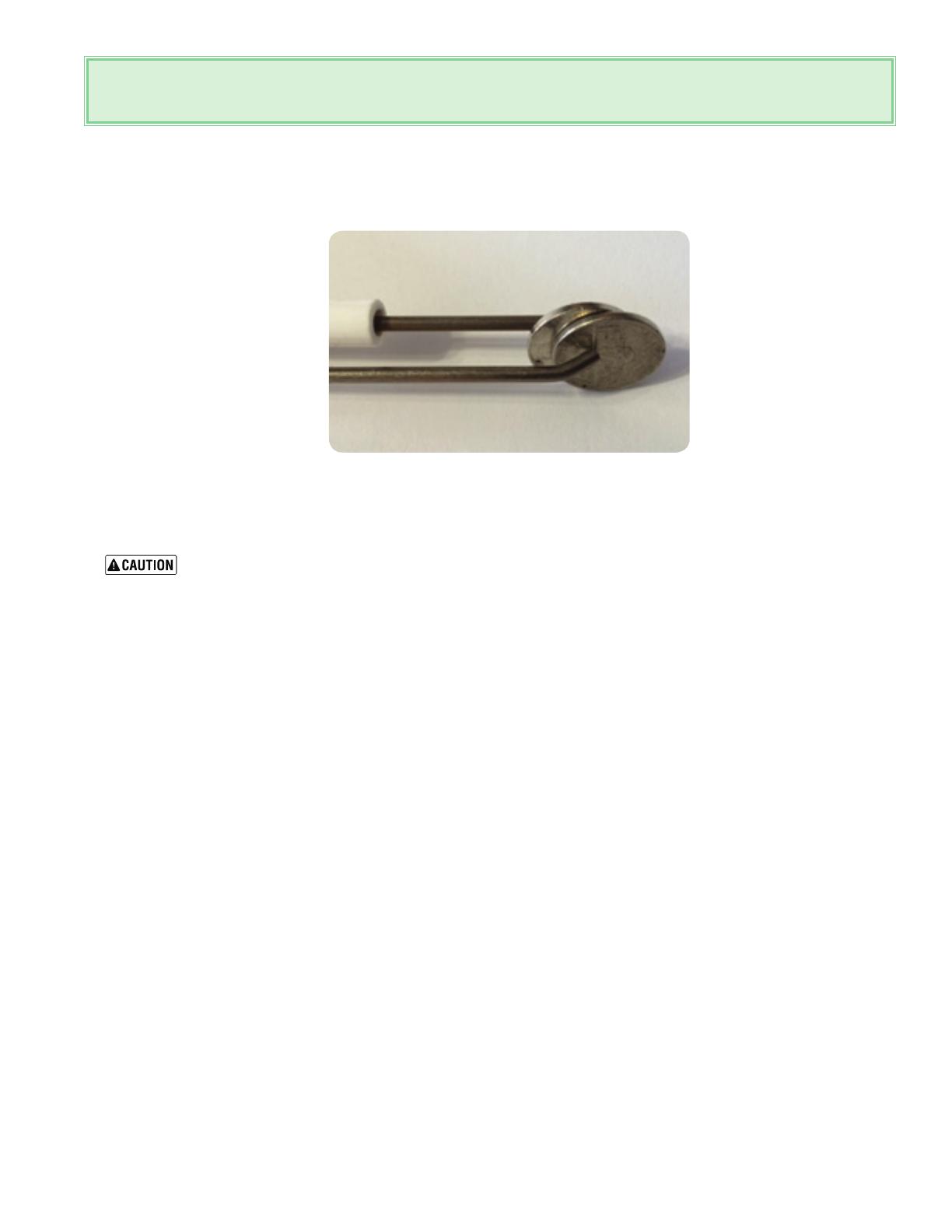
Checking ignitor gap…… Existing installation:
1. Shut off gas supply, remove the ignitor and inspect it for deformities / warped (gap should be 5/32” or the width of
two nickels which will have a “loose fit”.
2. With error code cleared on the control.
Carefully drape the ignitor over the plastic control housing being sure that it does not touch anything
and restart call for heat / check that the ignitor sparks ? If it does, the control board and ignitor are
working….further investigate gas supply and gas valve.
Existing installation:
1. Especially on LP fuel. A warped / deformed ignitor is caused by combustion not properly set per manual for CO
2
on
“HIGH and LOW fire as per the manual with combustion analyzer.
2. Boiler has “air trapped” within the heat exchanger (listen for gurgling / sloshing noise upon the circulators starting)
causing a much higher internal boiler combustion heat condition (where the boiler water is not absorbing the heat of
combustion) causing the ignitor to overheat.
F07….. “High Exhaust Temperature
The exhaust probe detects a higher than normal flue gas temperature of 176 degrees F for PVC vent material.
• Check for air in boiler heat exchanger, listen for sloshing / gurgling noises when pump starts. Boiler must be purged of
air entrapped in heat exchanger.
• Ventingmustbecheckedforproperlengths/longsweepelbowsmustbeinstalled.
• Nearboilersystempipingnotcorrectsize:FULL1inchforAB-155Cseriesboilers.
• Oncombiboilers,insurepumpselectorswitchissettoHIGH.
• ParameterP02 (boiler ramp speed) may be too aggressive for particular installation. (“ramp in degrees F per minute”)
factory set to 11, set to 6……which is a slower degree rise in boiler water temperature.
• Boilercentralheatingsetpointsetto190degreesF,whichinsomecases(dependingonexistingheatingsystempiping
and pumps) may be too high, and swing past set point and trip F07 code. Change user water temp set point for heat-
ing……Set boiler central heating water” temperature to 175-180 degrees F.
F37….”Incorrect system water pressure
• Systemwaterpressuretolow/codewillappearifwaterpressureis>8psi.
• Checkforsystemleakingwater/waterfeedvalvenotrellingsystem.
AquaBalance
®
CONTROL MODULE QUICK START GUIDE
Part number 550-100-316/0419
AquaBalance
®
CONTROL MODULE QUICK START GUIDE
  • Page 1 1
  • Page 2 2
  • Page 3 3
  • Page 4 4
  • Page 5 5
  • Page 6 6
  • Page 7 7
  • Page 8 8
  • Page 9 9
  • Page 10 10
  • Page 11 11
  • Page 12 12
  • Page 13 13
  • Page 14 14
  • Page 15 15
  • Page 16 16

WELL-McLAIN AquaBalance Series 2 User guide

Type
User guide

Ask a question and I''ll find the answer in the document

Finding information in a document is now easier with AI