Munters WM54K Fan 6pack Owner's manual

Type
Owner's manual

Munters WM54K Fan 6pack is a wall-mount fan with a damper door designed for efficient air movement and ventilation in agricultural and industrial settings. It features a durable fiberglass construction, a powerful motor for high airflow capacity, and a damper door for precise airflow control. With its easy installation and low maintenance requirements, the WM54K Fan 6pack is an ideal solution for providing fresh air, removing odors, and controlling humidity in various applications.

Munters WM54K Fan 6pack is a wall-mount fan with a damper door designed for efficient air movement and ventilation in agricultural and industrial settings. It features a durable fiberglass construction, a powerful motor for high airflow capacity, and a damper door for precise airflow control. With its easy installation and low maintenance requirements, the WM54K Fan 6pack is an ideal solution for providing fresh air, removing odors, and controlling humidity in various applications.

1© Munters Corporation, August 2021 QM1078r3
Instruction Manual
WM Fiberglass Wall Mount Fan
with Damper Door - 6 pack
Models: WM54xKxCB-6PK
WM54K
Wall Mount Fan
with Damper Door
6-pack
© Munters Corporation, August 2021
2QM1078r3
Thank You:
Thank you for purchasing a Munters Wall Mount Fan with Damper. Munters equipment is designed to be the
highest performing, highest quality equipment you can buy. With the proper installation and maintenance it will
provide many years of service.
Please Note:
To achieve maximum performance and insure long life from your Munters product it is essential that it be installed
and maintained properly. Please read all instructions carefully before beginning installation.
Warranty:
For Warranty claims information see the “Warranty Claims and Return Policy” form QM1021 available from the
Munters Corporation office at 1-800-227-2376 or by e-mail at [email protected].
Conditions and Limitations:
• Products and Systems involved in a warranty claim under the “Warranty Claims and Return Policy” shall have
been properly installed, maintained and operated under competent supervision, according to the instructions
provided by Munters Corporation.
• Malfunction or failure resulting from misuse, abuse, negligence, alteration, accident or lack of proper
installation or maintenance shall not be considered a defect under the Warranty.
WM54K Fiberglass Wall Mount Fan with Damper
Instructions for Use and Maintenance
3© Munters Corporation, August 2021 QM1078r3
Index
Chapters Page
1. Unpacking the Equipment 4
1.1 Parts List 4
1.2 Fan Dimensions 6
1.3 Tools for Installation 6
2. Installation Instructions 7
2.1 Wall Framing 7
2.2 Fan Assembly 8
2.3 Damper Door Installation 11
2.4 Cone Installation 17
2.5 Motor Mounting 21
3. Electrical Wiring 26
3.1 Recommended Wiring 27
4. Operation 28
5. Maintenance 29
6. Winterizing 31
6.1 Winterizing 31
6.2 Winter Weather Protection 31
7. Troubleshooting 32
8. Exploded View and Parts List 33-35
© Munters Corporation, August 2021
4QM1078r3
1.1 Parts List
Unpacking the Equipment 1.
Each Crate Includes Parts to build 6 fans:
Each WM54K Fan Requires:
1 – Orifice Panel, Fiberglass
1 – Propeller
1 – Tube Strut, PWDCTD
1 – Motor
1 – Drip Shield, AL
1 – Main Frame Assembly, AL
1 – Door Assembly, PL
4 – Cone Sections, PL
1 – Cone Guard
1 – Inlet Guard
½ – Bulk Parts Package (BK1154) For 2 Fans
BK1154 – ½ of Bulk Parts Package needed for 1 – WM54K
1 – Motor Base Bracket, CTD-GZ
1 – Belt Tensioner Bracket, CTD-GZ
4 – Cone Support Brackets, PC Type, GZ
4 – Cone/Strut Mounting Brackets, GZ
1 – V-Belt, A-Section
1 – Hub with Bearings and Shaft
1 – Motor Sheave, CI
1 – Prop Sheave, AL
1 – 3” Idler Pulley, A-Section C.I., Blue
1 – Rotary Tensioner Arm, AL
1 - Motor Mount Stiffener Bracket, GZ
2 – Tension Springs, 11.0”L./10.8”L., SS
1 – Hardware Package (HP1389)
1 – Coated Cable with ferrule, 100”L.
2 – Wing for Damper Door, HDPE, BLK
5© Munters Corporation, August 2021 QM1078r3
[B]
[C]
[D]
[E]
[F]
[G]
[H]
[J]
[K]
[L]
[M]
[N]
[R]
[T]
[X]
[Y]
Unpacking the EquipmentChapter 1
[AA]
[BB]
[CC]
[DD]
[EE]
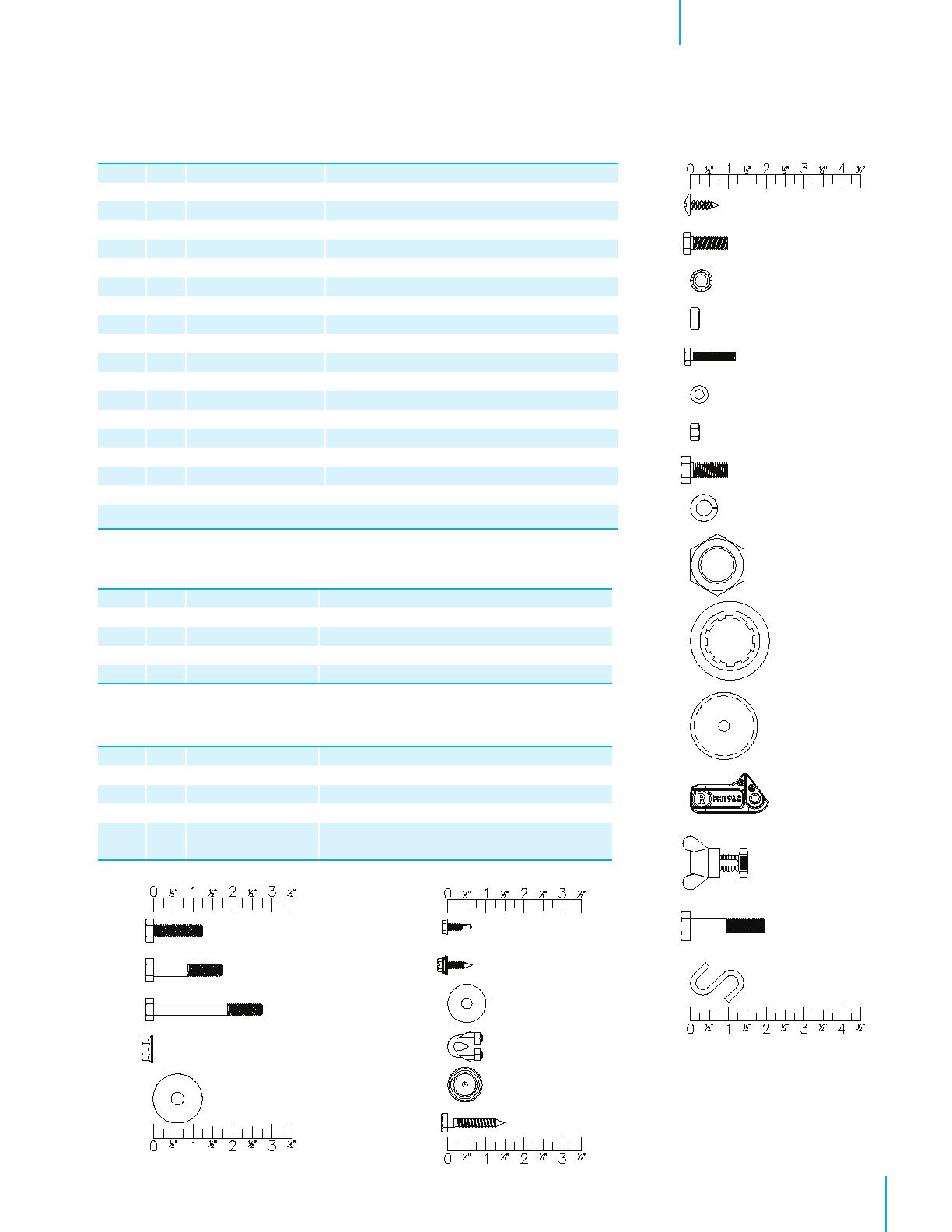
HP1389 – Hardware Package for 1 – WM54K
ID Qty. Cat. No. Description
[B] 1 KS1901 6.3mm x 19mm Tapping Screw, ZP
[C] 4 KS1928 M8-1.25 x 25mm Hex Bolt, ZP (HP1382 only)
[D] 4 KW4906 M8 Star Lock Washer, BLK
[E] 4 KN1849 M8-1.25 x 8mm Hex Nut, ZP
[F] 4 KS1926 M6-1.0 x 30mm Hex Bolt, ZP
[G] 4 KW4901 M6 x 12mm Flat Washer, ZP
[H] 4 KN1855 M6-1.0 x 6mm Hex Nut, ZP
[J] 1 KS1931 M10-1.5 x 25mm Hex Bolt, ZP
[K] 1 KW3509 10mm Splitlock Washer, ZP
[L] 1 KN1860 M25-2.0 x 10mm Hex Nut, ZP
[M] 1 KX1130 Shaft Shield for Prop Sheave, AL
[N] 1 KX1208 40mm Cover Cap, Black PL
[R] 8 FH1968 1-Hole Pivoting Shutter Clip, PL
[T] 1 AC0211 & AC0212 Azuma Bolt & Nut, Blue PL
[X] 1 KS1046 M10-1.5 x 50mm Hex bolt, ZP
[Y] 2 KX1059 1” S-Hook, ¹⁄₁₆”Wire, SS
1 HK1001 Hardware Kit WM54K Fan Assembly, #1 of 2
1 HK1002 Hardware Kit WM54K Fan Assembly, #2 of 2
1 LB2647 Specifi cation Label for WM54K
HK1001 – Hardware Kit for 1 – WM54K Fan
ID Qty. Cat. No. Description
[AA] 18 KS1007 516”-18 x 1.25” Hex Head Bolt, SS
[BB] 4 KS1029 516”-18 x 1.75” Hex Head Bolt, SS
[CC] 7 KS1075 516”-18 x 2.75” Hex Head Bolt, SS
[DD] 37 KN0704 516”-18 SRTD Flange Nut, SS
[EE] 10 KW3011 516” x 1¼ ”O.D. Flat Washer, SS
HK1002 – Hardware Kit for 1 – WM54K Fan
ID Qty. Cat. No. Description
[FF] 4 KS2258 #10-16 x ⁵⁄₈” TEK Screw, SS
[GG] 7 KS1400 #10-12 x 34”, SLTDHX, Seal-Washer Screw, ZP
[HH] 1 KW3012 ¹⁄₄” x 1”O.D. Flat Washer, SS
[JJ] 2 AC1381 18” Dia. Cable Clamp, ZP
[KK] 2 KX1158 Hole Plug, 0.73”-0.76” Dia., BLK PL
[LL] 1 KS2463 14” x 1.5” HEX Lag Screw,ZP
[FF]
[GG]
[HH]
[JJ]
[KK]
[LL]
© Munters Corporation, August 2021
6QM1078r3
1.2 Fan dimensions
Fan Specifications: 60Hz shown (50Hz available)
Power: 115/230 VAC* or 208-230/460 VAC
Phase: 1 or 3
*Available voltages vary depending on HP
Unpacking the EquipmentChapter 1
Dimensions:
Size A B C* D - Dia. E F Wall Openings
54” 60”W. x 60” H. 49” 612”66
516”3
316”4
34”56
12W. x 5612”H.
Wall Opening (W.O.)
D - Dia.
F
A
AB
Guard
E
C
1.3 Tools required for installation
10mm [38”] Socket
13mm [ ½”] Socket
17mm [1116”] Socket or Wrench
27mm [1116”] Wrench
36mm Socket or Wrench
516” Socket or Wrench
38” Socket
Phillips Screwdriver, #3 Size
18” Drill Bit
532” Hex Wrench
Wire Cutting Pliers
*Dimension varies depending on wall construction and motor configuration.
7© Munters Corporation, August 2021 QM1078r3
Installation Instructions 2.
2.1 Wall framing
Step 1
Construct framed opening to correct size according to the Wall Opening listed in chart A below.
See Figure 1A and 1B. When installing exterior sheet metal before fan, leave 2” of the framing
exposed on all sides so the orifice can mount flush to the frame.
Minimum Spacing
'Z'
Chart A
Wall Opening
(W. x H.)
Fan Dia.
54” 56½” W. x 56½” H.
Figure 1B 4 x 4 Post Construction - Elevation View
Ceiling
Framing
H
(see chart A)
12"
W
(see chart A)
See minimum
spacing notes in
Chart A
Z
2 x 8 Header boards
4 x 4 or
4 x 6 Posts
2 x 4
Framing
2 x 8 Banner boards
Ceiling
4 x 4 or 4 x 6 Posts
W
(see chart A)
H
(see chart A)
Note:
Damper doors should
be carefully set aside
out of direct sunlight
until needed.
Center To Center
Dimension
60” Minimum
Figure 1A Frame Construction
5612”W.
Top View
60”W. O.C.
W x H Wall Opening
Sheet Metal Opening
Stud Wall
12” recommended; 3½” minimum
© Munters Corporation, August 2021
8QM1078r3
2.2 Fan assembly
Step 2
Place tube strut on saw horses or a flat work surface. The large center hole should be pointing horizontally.
Attach the Motor Base Bracket and the Belt Tensioner Bracket to the Tube Strut using (3) Long Bolts [CC],
(2) Washers [EE] and (3) Nuts [DD]. The Motor Bracket and the Tensioner Bracket share the middle hole.
See Figure 2A.
Figure 2A
Installation InstructionsChapter 2
Step 2B
Attach the 3” Idler Pulley to the Tensioner Arm using Bolt [X]. Then attach the Tensioner Arm assembly to the
Tensioner Bracket using Bolt [J] and Splitlock Washer [K]. Finger tighten only at this time.
See Figure 2B.
Next attach the Specification Label to the Tube Strut as shown, and then mark the box for the appropriate
model fan.
Figure 2B
Tube Strut
Motor Base Bracket
Tensioner Bracket
Washer [EE]
Long Bolts [CC]
Idler Pulley
Tensioner Arm
Bolt [X]
Washer [K]
Bolt [J]
Nuts [DD]
Label
9© Munters Corporation, August 2021 QM1078r3
Step 3
Attach Prop Sheave to Hub using (4) Bolt [F], Washer [G] and Nut [H]. See Figure 3.
Prop Sheave
Hub
Bolt [F]
Washer [G]
Prop Sheave
Nut [H]
Bolt [F]
Hub
Washer [G]
Step 4
Rotate Tube Strut on saw horses so Motor Bracket is pointing up. Slide Shaft Shield [M] over hub shaft
as shown in Figure 4. Attach Sheave/Hub Assembly to Tube Strut using (1) Hex Nut [L] and tighten to
52 ft-lbs [70 N-m] torque. See Figure 4. Place Plastic Cover Cap [N] over Hex Nut and fasten in place
with (1) Tapping Screw [B]. See Figure 4. Set aside the Strut Assembly for use in a later step.
Figure 3
Shaft Shield [M]
Hex Nut [L]
Cap Cover [N]
Tapping Screw [B]
Figure 4
Installation InstructionsChapter 2
Hub Assembly
© Munters Corporation, August 2021
10 QM1078r3
Step 5
Place Orifice Panel on saw horses with the round orifice pointing up and place (1) Cone/Strut Mounting
Bracket in each corner of the Orifice Panel. See Figure 5.
Mounting Bracket
Orifi ce Panel
Step 6
Corners of Orifice Panel with 2 holes are corners where Strut Assembly attaches. Secure Strut Assembly using
(4) Long Bolts [CC], (6) Washers [EE] and (4) Nuts [DD]. In the opposite corners attach Cone/Strut Mounting
Bracket to the orifice using (1) Short Bolt [AA], Washer [EE] and Nut [DD]. See Figure 6.
Figure 5
Figure 6
Long Bolt [CC]
Washer [EE]
Washer [EE]
Nuts [DD]
Drain Hole
Washer [EE]
Short Bolt [AA]
Nuts [DD]
Installation InstructionsChapter 2
11© Munters Corporation, August 2021 QM1078r3
Step 7
Attach Propeller to Hub Assembly using (4) Bolts [C], Washers [D] and Nuts [E]. Tighten bolts to 180 in-lbs.
of torque. See Figure 7.
Figure 7
WM54K Shown
Propeller
Installation InstructionsChapter 2
Nut [E]
Step 8
Slide Main Frame Assembly onto Orifice Panel with pin on Main Frame opposite the drain holes.
See Figure 8A. Line up 4 holes in Main Frame with holes in the Orifice and fasten using (4) TEK Screws [FF].
See Figure 8B.
Hole in orifi ce panel
Figure 8A Figure 8B
Bolt [C]
Washer [D]
Pin
Main Frame
Orifi ce Panel
TEK Screw [FF]
2.3 Damper Door Installation
Drain Hole
© Munters Corporation, August 2021
12 QM1078r3
Installation InstructionsChapter 2
Step 9
Attach Drip Shield to bottom of framed opening using (3) Barn Screws (Not Provided). See Figure 9A and 9B.
If a 4” wall is used a support board must be installed as shown in Figure 9B. Be sure not to deform Drip Shield
when installing screws.
Figure 9A Figure 9B
Drip Shield
Barn Screw
(not provided)
4” Wall
6” Wall
Drip plate
Drip plate
Support board
Barn Screw Barn Screw
Step 10
Locate Drain Hole in Orifice Panel. This is the bottom of the Panel. Set bottom edge of panel on Drip Shield
ledge and center panel on opening. Secure Panel to wall using (16) Barn Screws (Not Provided).
See Figure10A and 10B.
Figure 10A Figure 10B
Drain Hole
Drip Shield ledge
Orifi ce Panel
Barn Screws (Not Provided)
13© Munters Corporation, August 2021 QM1078r3
Installation InstructionsChapter 2
Step 11
Carefully remove folded door assembly from box. Open doors and lay them flat on solid surface with the
Munters Logo down. The Bottom of the doors has the Hinge Pin with the Nylon Washers. The Wing sits down
in the Groove of the upper right and lower left doors. For the WM54 the Wing will start just after the last
spring mounting dimple and follow the Groove. Make sure Wing is seated in bottom of Groove and fasten in
place using (3) Seal-Washer Screws [GG] per wing. Make sure Hinge Pins do not fall out. See Figure 11.
Figure 11
Seal-Washer
Screw [GG]
Wing
Wing
Groove in Door
Spring Mounting Dimples
© Munters Corporation, August 2021
14 QM1078r3
Installation InstructionsChapter 2
Step 12
Carefully turn doors over and pull upper Latch Pin down until the end is flush with top of doors. Make sure
Long Hinge Pin (bottom) does not fall out. See Figure 12.
Figure 12
Latch Pin
Long Hinge Pin
15© Munters Corporation, August 2021 QM1078r3
Step 13
Being careful not to let pin fall out, set Doors into Main Frame with Hinge Pin in hole at bottom plate of
Main Frame and push top of Doors into place. See Figure 13.
Installation InstructionsChapter 2
Figure 13
Hinge Pin
Door
Step 14
Separate doors and push them into closed position. Push Latch Pin up into place, then turn short leg of
Latch Pin into recess of door. Secure in place using Seal-Washer Screw [GG] and Flat Washer [HH].
Latch Pin should extend up through upper plate in Main Frame. See Figure 14.
Figure 14
Latch Pin
Latch Pin Leg
Flat Washer [HH]
Seal-Washer Screw [GG]
© Munters Corporation, August 2021
16 QM1078r3
Step 15
Find Coated Cable and insert end opposite ferrule into small hole in upper plate of Main Frame. Pull it
through until ferrule stops at the plate. See Figure 15.
Installation InstructionsChapter 2
Hole in Main Frame
Ferrule End
Step 16
On room side of each door drill an 18” dia. hole in each door through one of the dimples, as shown. For WM54
drill the 6th dimple from the center in both upper quadrants. See Figure 16.
Figure 15
Figure 16
Drill 6th Dimple
Drill 6th Dimple
17© Munters Corporation, August 2021 QM1078r3
Step 17
From the inside attach each S-Hook [Y] to hole in upper plate of Main Frame, from the door side through the
Main Frame toward the outside. Then attach each Tension Spring to S-Hook [Y] using end of spring with loop.
Stretch spring and insert opposite end into hole drilled in door previously. See Figure 17.
Figure 17
Installation InstructionsChapter 2
Step 18
Place all 4 cone sections on a flat surface with tabs from one facing slots of the next. See Figure 18A.
Curl up tab end of first cone section and insert tabs up into slots in the next cone section. A mallet may be
needed to seat slots over tabs completely. See Figure 18B. Repeat this step until all 4 cone sections are
connected and laying flat.
2.4 Cone Installation
Figure 18A
Figure 18B
Hole in upper plate
Drilled Hole in
Damper Door
Tension Spring
S-Hook [Y]
Hole in upper plate
S-Hook [Y]
Tension Spring Loop End
© Munters Corporation, August 2021
18 QM1078r3
Installation InstructionsChapter 2
Step 19A
Fasten each of the joints in the single outer hole using (1) Short Bolt [AA] and Nut [DD], with the nut on
the side with the tabs. At the inner pair of holes of each joint attach (1) Cone Support Bracket to the inner
hole using (1) Bolt [AA] and Nut [DD] with the bolt head on the side with the tabs. See Figure 19A.
Nut [DD]
Short Bolt [AA]
Outer hole
Nut [DD]
Short Bolt [AA]
Inner hole
Figure 19A
Step 19B
Stand cone sections on end and curl ends around to form cone with Cone Support Bracket on outside and tabs
on inside. Insert remaining tabs into slots so tabs are inside cone and fasten final joint using (1) Short Bolt [AA]
and Nut [DD], with nut on inside of cone. At the inner pair of holes attach (1) Cone Support Bracket to the
inner hole using (1) Short Bolt [AA] and Nut [DD] with bolt head on inside of cone. See Figure 19B.
Figure 19B
Cone Support Bracket
Short Bolt [AA]
Short Bolt [AA]
Nut [DD]
Nut [DD]
Cone Support Bracket
19© Munters Corporation, August 2021 QM1078r3
Figure 20A
Step 20A
Install cone onto fan by putting top of cone over top of fan. The hole in tab of one cone section should slide
down over the Frame Pin in the Main Frame assembly. Allow remainder of cone to slide over orifice panel
making sure cone support brackets remain on outside of cone. See Figure 20A.
Frame Pin
Installation InstructionsChapter 2
Hole in Tab of Cone Section
Step 20B
Place end of Cone Support Bracket with slot over bolt holding Cone/Strut Mounting Bracket to the orifice and
secure with Nut [DD]. See Figure 20B. Secure Cone to Fan installing Medium Bolt [BB] through the remaining
hole in the Cone Support Bracket and fasten with Nut [DD]. A long screwdriver may be needed to help align
the holes through Cone Support Bracket, Cone, Main Frame and Orifice. Repeat process for all 4 Cone
Support Brackets. See Figure 20B.
Figure 20B
Nut [DD]
Medium Bolt [BB]
Nut [DD]
Use this hole for WM54K
© Munters Corporation, August 2021
20 QM1078r3
Installation InstructionsChapter 2
Step 21
Insert guard into cone with the eyelets facing you. Install eyelets over bolts already installed in cone and fasten
with Nut [DD]. Secure remaining eyelets using Short Bolt [AA] and Nut [DD]. See Figure 21.
Nut [DD]
Nut [DD]
Previously installed - Bolt and Nut
Step 22
Loop Coated Cable that was installed in a previous step, around the lower, middle joint in guard and fasten to
itself with Azuma Bolt & Nut [T]. Make sure cable is pulled snug. See Figure 22.
Figure 21
Figure 22
Azuma [T]
Short Bolt [AA]
Coated Cable
Note:
When installing cable in
temperatures BELOW 60°F,
leave cable slightly slack
(do not overtighten).
  • Page 1 1
  • Page 2 2
  • Page 3 3
  • Page 4 4
  • Page 5 5
  • Page 6 6
  • Page 7 7
  • Page 8 8
  • Page 9 9
  • Page 10 10
  • Page 11 11
  • Page 12 12
  • Page 13 13
  • Page 14 14
  • Page 15 15
  • Page 16 16
  • Page 17 17
  • Page 18 18
  • Page 19 19
  • Page 20 20
  • Page 21 21
  • Page 22 22
  • Page 23 23
  • Page 24 24
  • Page 25 25
  • Page 26 26
  • Page 27 27
  • Page 28 28
  • Page 29 29
  • Page 30 30
  • Page 31 31
  • Page 32 32
  • Page 33 33
  • Page 34 34
  • Page 35 35
  • Page 36 36

Munters WM54K Fan 6pack Owner's manual

Type
Owner's manual

Munters WM54K Fan 6pack is a wall-mount fan with a damper door designed for efficient air movement and ventilation in agricultural and industrial settings. It features a durable fiberglass construction, a powerful motor for high airflow capacity, and a damper door for precise airflow control. With its easy installation and low maintenance requirements, the WM54K Fan 6pack is an ideal solution for providing fresh air, removing odors, and controlling humidity in various applications.

Ask a question and I''ll find the answer in the document

Finding information in a document is now easier with AI