
Model:RLDV3282A

CONTENTS
14
15
16
17
18
19
1
2
2
3
3
6
7
3
4
8
9
8
8
9
9
10
10
4
6
6
7
12
13
13
13
SAFETY
PRECAUTION
IMPORTANT
SAFETY
INSTRUCTION
ACCESSORIES
GETTING
STARTED
5
CONTROL
REFERENCE
GUIDE
WALL MOUNT
INSTALLATION
INITIAL SETUP
TV SETUP
CONNECTIONS
Remote Control
Front View
Back View
Side View
Antenna Connection
AV Connection
YPbPr Connection
HDMI Connection
VGA Connection
Headphone Connection
Power Cord Connection
Coax(SPDIF) Connection
Putting The Unit On A Proper Place
Turning The Unit On For The First Time
Source Selection
TV(CHANNEL) Menu
Picture Menu
Audio Menu
Time Menu
Setup Menu
LOCK(Parental) Menu
1
English
10
11

CONTENTS
20
11
10
12
14
32
15
16
21
24
26
27
30
30
33
34
DISC
FORMATS
CD / DVD
OPERATION
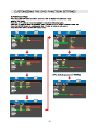
CUSTOMIZING
THE DVD
FUNCTION
SETTINGS
DISPLAY
MODE
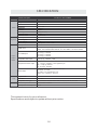
SPECIFICATION
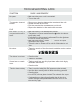
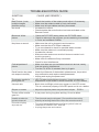
TROUBLE-
SHOOTING
GUIDE
Basic Operations
Special Functions
Mp3 / JPEG Playback
PC Formats
Video Formats
DVD Symptom
TV Symptom
SAFETY CLASS :This is an IEC safety class I product
and it must be grounded for safety.
DVD Menu
13 MAINTENANCE 29

*
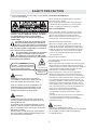
SAFETY PRECAUTION
CAUTION
•
•
•
WARNING:
PLACEMENT INFORMATION
SAFETY INFORMATION
CONDENSATION INFORMATION
RATING PLATE LOCATION
FCC STATEMENTS
CLASS 1 LASER
PRODUCT
WARNING:
CAUTION MARKING WAS LOCATED AT THE REAR
OF THE APPARATUS.
WARNING:TO REDUCE THE RISK OF ELECTRIC
SHOCK,DO NOT REMOVE COVER(OR BACK)
NO USER SERVICEABLE PARTS INSIDE.
REFER SERVICING TO QUALIFIED SERVICE
PERSONNEL.
The lightning flash with arrowhead symbol,
within an equilateral triangle,is intended to
alert the user to the presence of uninsulated
“dangerous voltage”within the product's enclosure
that may beof sufficient magnitude to constitute a
risk of electric shock to persons.
The exclamation point within an equilateral
Triangle is intended to alert the user to
The presence of important operating and
maintenance (servicing) instructions in the literature
accompanying the appliance.
CAUTION
INVISIBLE LASER RADIATION WHEN
OPEN AND INTERLOCKS DEFEATED
AVOID EXPOSURE TO BEAM
This product
Contains a low
power laser device.
DANGER OF EXPLOSION IF BATTERY IS
INCORRECTLY REPLACED. REPLACE ONLY
WITH THE SAME OR EQUIVALENT TYPE.
USE OF CONTROLS OR ADJUSTMENTS OR
PERFORMANCE OF PROCEDURES OTHER
THAN THOSE SPECIFIED MAY RESULT IN
HAZARDOUS RADIATION EXPOSURE.
•
•
TO REDUCE THE RISK OF FIRE OR ELECTRIC
SHOCK, DO NOT EXPOSE THIS APPLIANCE TO
RAIN OR MOISTURE.
TO REVENT FIRE OR SHOCK HAZARD, DO NOT
EXPOSE THIS UNIT TO RAIN OR MOISTURE. DO
NOT PLACE OBJECTS FILLED WITH LIQUIDS ON
OR NEAR THIS UNIT.
SHOULD ANY TROUBLE OCCUR, DISCONNECT
THE AC POWER CORD AND REFER SERVICING
TO A QUALIFIED TECHNICIAN.
Do not use this unit in places that are extremely
hot, cold, dusty or humid.
Do not restrict the airflow of this unit by placing it
somewhere with poor airflow, by covering it with
a cloth, by placing it on bedding or carpeting.
When connecting or disconnecting the AC power
cord, grip the plug and not the cord itself. Pulling
the cord may damage it and create a hazard.
When you are not going to use the unit for a long
period of time, disconnect the AC power cord.
When left in a heated room where it is warm and
damp, water droplets or condensation may form
inside the equipment. When there is condensation
inside the unit, the unit may not function normally.
Let the unit stand for 1-2 hours before turning the
power on or gradually heat the room and let the
unit dry before use.
The rating plate is located on the rear of the unit.
NOTE: This unit has been tested and found to comply
with the limits for a Class B digital device, pursuant
to Part 15 of the FCC Rules. These limits are designed
to provide reasonable protection against harmful
interference in a residential installation.
This unit generates, uses and can radiate radio
frequency energy and, if not installed and used in
accordance with the instructions, may cause harmful
interference to radio communication. However, there
is no guarantee that interference will not occur in a
particular installation. If this unit does cause harmful
interference to radio or television reception, which
can be determined by turning the unit off and on, the
user is encouraged to try to correct the interference
by one or more of the following measures:
- Reorient or relocate the receiving antenna.
- Increase the separation between the unit and
receiver.
-Connect the unit into an outlet on a circuit different
from that to which the receiver is connected.
- Consult the dealer or an experienced radio/TV
technician for help.
Changes or modifications to this
unit not expressly approved by the party responsible
for compliance could void the user authority
to operate the unit.
•
•
•
•
•
1

IMPORTANT SAFETY INSTRUCTIONS
1)Read these instructions.
2)Keep these instructions.
3)Heed all warnings.
4)Follow all instructions.
5)Do not use this apparatus near water.
6)Clean only with a dry cloth.
7)Do not block any ventilation openings.
Install in accordance with the
manufacturer's instructions.
8)Do not install near any heat sources such
as radiators, heat registers, stoves, or
other apparatus (Including amplifiers) that
produce heat.
9)Do not defect the safety purpose of the
polarized or grounding-type plug.
A polarized plug has two blades with one
wider than the other.
A groundingtype plug has two blades
and a third grounding prong.
The wide blade or the third prong is
provided for your safety.
If the provided plug does not fit into your
wall outlet, consult an electrician for
replacement of the obsolete outlet.
10)Protect the power cord from being walked on
or pinched particularly at plugs, convenience
receptacles, and the point where they exit
from the apparatus.
11)Only use attachments / accessories specified
by the manufacturer.
12)Use only with the cart, stand,
tripod, bracket, or table
specified by the manufacturer,
or sold with the apparatus.
When a cart is used, use caution when
moving the cart / apparatus combination to
avoid injury from tip-over.
13)Unplug this apparatus during lightning
Storms or when unused for long periods of
time.
14)Refer all servicing to qualified service
personnel. Servicing is required when the
apparatushas been damaged in any way,
such as the power cord or plug is damaged,
liquid has been spilled or objects have fallen
into the apparatus, the apparatus has been
exposed to rain or moisture, does not operate
normally, or has been dropped.
15)To prevent electric shock, ensure the grounding
pin on the AC cord power plug is securely
connected.
2

ACCESSORIES
Please check and identify the supplied accessories.
............................................................................................................ .........
................................................................................................................
.................................................................................................................
GETTING STARTED
USING THE REMOTE CONTROL
TO INSTALL THE BATTERIES
BATTERY REPLACEMENT
CAUTION
1.Open the battery door. 2. Insert 2 "AA" batteries
: Danger of explosion if battery is incorrectly replaced.
NOTES
WARNING :
x 2
x 1
x 1
x 1
Remote control ..................................................................................................................
Remote control
Battery(AA)
Warranty Card
Instruction Manual
·Point the remote control at the remote sensor located on the unit.
·When there is a strong ambient light source, the performance of the infrared remote sensor
·may be degraded, causing unreliable operation.
·The recommended effective distance for remote operation is about 16 feet (5 meters).
When the batteries become weak, the operating distance of the remote control is greatly
reduced and you will need to replace the batteries.
·If the remote control is not going to be used for a long time, remove the batteries to avoid
damage caused by battery leakage corrosion.
·Do not mix old and new batteries.Do not mix ALKALINE, standard (CARBON-ZINC) or
rechargeable (NICKEL-CADMIUM) batteries.
·Always remove batteries as soon as they become weak.
·Weak batteries can leak and severely damage the remote control.
Do not dispose batteries in a fire. Batteries may explode or leak.
Batteries shall not be exposed to excessive heat such as sunshine, fire or the like.
3
................................................................................................. x 1
................................................................................................................... x 1
Base stand and 4 screws
Screw driver

CONTROL REFERENCE GUIDE
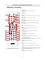
REMOTE CONTROL
1.STANDBY
To switch on the TV or make the TV into
standby mode.
2.EJECT
To eject a disc.
3.INFO
Show the information of the program you are watching.
4.SOURCE
Press this button to select an input source.
5.PMODE
Press this button to select a picture mode for different
picture qualities.
6.SMODE
Press this button to select sound setting for different
sound effects.
7.0-9
Allows you to change the channel of the TV.
8.
Switches back and forth between the current and
previous channels.
9.SLEEP
To select the amount of time before your TV turns
Off automatically.
10.VOL+/VOL-
Increases/Decreases the Volume control.
11.CH+/CH-
Skips to the next/previous channel on TV mode.
12.UP/DOWN/LEFT/RIGHT
Moves the cursor upward/downward/to the left/to the right
when making a selection.
13.MENU
Displays the OSD Menu of the TV.
14.CC
Press the button to enter into the CC mode.
TITLE
To goto the title menu if the DVD disc has a title page.
15.MTS
To change among STEREO, MONO and SAP. If there is no
second language available for the signal received, LED
Display audio will output to mono.
D.MENU
To show the menu of the DVD disc.
4
5
1
2
3
6
8
9
12
7
11
13
10
15
14
19
18
23
22
27
26
31
30
16
17
20
21
24
25
28
29
32
33
FAVFAV
EPGEPG
4
Universal Remote Code: 1218
(Universal Remote Control is not included)

CONTROL REFERENCE GUIDE
REMOTE CONTROL
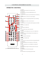
16.ENTER
Press to confirm selections on a menu screen.
17.D.SETUP
Press this button to show the DVD SETUP menu.
18.Play/Pause
Press this button to play or pause the DVD you’re watching.
19.Exit
Press this button to exit the on screen display.
Stop
Press this button to stop playing the DVD you’re watching.
20.MUTE
Press this button to mute or restore sound.
21.AUDIO
Press this button to change the audio language of the DVD.
22.
Fast reverse in DVD mode.
23.
Fast forward in DVD mode.
FAV
Press this button enter the favourite list.
24.ZOOM
To select a screen display size on your TV in DVD mode.
25.GOTO
Press this button to start playing the disc program from
the time you want.
26.
Previous chapter in DVD mode.
27.
Next chapter in DVD mode.
28.EPG
Press this button to select the electronic programme guide.
29.SUBTITLE
To show the subtitle for the program you're watching.
30.PRO
To edit the program list of your DVD disc in DVD mode.
31.ANGLE
To select different angles to which the picture suits your
preference.
32.REPEAT
Press this button for repeat the program.
33.AB
Press this button for repeat play point A and B.
4
5
1
2
3
6
8
9
12
7
11
13
10
15
14
19
18
23
22
27
26
31
30
16
17
20
21
24
25
28
29
32
33
FAVFAV
EPGEPG
Universal Remote Code: 1218
(Universal Remote Control is not included)
5

CONTROL REFERENCE GUIDE
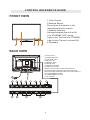
FRONT VIEW
1.Color Screen
2.Remote Sensor
Do not block this sensor or the
remote control will not work.
3.Standby Indicator
Indicates whether the unit is ON
or in STANDBY (OFF) mode.
Light in red: The unit is in STANDBY.
Light in blue:The unit is turned ON.
4.Speakers
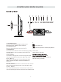
BACK VIEW
6
32
44 1
1.Power Cord
2.Headphone Jack
3.Coax OUT Jack
4.Service Port
5.HDMI IN Jacks
6.VGA IN Jack
7.PC ADUIO IN Jack
8.AUDIO OUT Jack
(Audio out-This connection is for sending
out analog audio signal to the 2nd equipment.
Red is for Right Channel,white is for left channel.)
9.TV ANTENNA Terminal
10.COMPONENT IN Jack
11.AV IN Jack
1

1.
Turn on the TV by pressing the button once.
Press the button again to turn off the TV.
2. SOURCE
3. MENU
This button activates the On Screen Display (OSD).
If a sub-menu is active, pressing this button will
exit the OSD.
4. CH+
This button changes the TV channel up.If the OSD
is active,this button functions as up for the menu.
5. CH-
This button changes the TV channel down.If the
OSD is active,this button functions as down for
the menu.
6. VOL+
This button increases the TV's volume.If a sub-menu is
active,pressing this button will move the select right.
7. VOL-
This button decreases the TV's volume.If a sub-menu
is active,pressing this button will move the selection left.
STANDBY Button
Button
Button
But t on
But t on
But t on
But t on
Press to select the input source of the TV.
8.
Press to eject a disc.
Press this start pause or resume playback of
a disc.
CONTROL REFERENCE GUIDE
9.Disc Slot
Insert discs to disc slot
SIDE VIEW
(Right direction:put the mirror side of
the disc facing yourself)
7
9

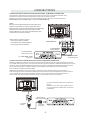
CONNECTIONS
CONNECTING A TV ANTENNA / CABLE / S A TELLITE
To view television channels correctly, a signal must
be received from one of the following sources:
- An indoor or outdoor aerial antenna
- A cable system
- A satellite system
For receiving over-the-air TV broadcasts, we
recommend that you use an external fixed antenna.
Should you require the use of a temporary antenna,
please ensure that you purchase an antenna with
sufficient ability to receive in weak signal areas.
Only when you are in close proximity to a transmitter
will a temporary antenna reproduce a signal as
strongly as a fixed antenna.
To connect to other equipment such as a VCR, camcorder, satellite system or cable, etc.
CONNECTING AN A/V DEVICE
NOTE
CONNECTING DEVICES WITH A COMPOSITE (YELLOW RCA-TYPE)
VIDEO OUTPUT
Connecting to a VCR / Video Game System / Camcorder
AUDIO VIDEO OUT
NOTE
To connect A/V devices such as a VCR, video game system or camcorder.
Connect the AUDIO / VIDEO cable (not included) as shown.
Make sure you connect the cable from the other equipment ( and ) to this unit
Please refer to the user manual
for the other equipment for
more information.
Satellite, cable or TV antenna
cable to TV ANTENNA
terminal (cable not included)
To AUDIO / VIDEO
IN jacks
To AUDIO / VIDEO
OUT jacks
(AV in)
8

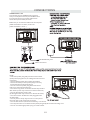
CONNECTIONS
CONNECTING A HIGH-DEFINITION (HD) SOURCE USING CONNECTION
NOTE
COMPONENT
High-Definition (HD) Devices with component video output must be connected to the Y input.
Connect the component video cable and audio cable (not included) as shown.
Make sure you connect the component video cable and audio cable from the other equipment
When connecting a DVD player to the television,
the picture resolution is solely dependent upon
the resolution supported by the DVD player attached.
DVD player resolutions vary from 480i to 1080i.
and this television can support DVD players up to
a maximum resolution of 1080i.
PbPr
* May require a subscription
for receiving HD channels,
check with your cable/satellite
service provider for details.
To COMPONENT
VIDEO OUT jacks
CONNECTING A HIGH-DEFINITION (HD) SOURCE USING HDMI CONNECTION
HDMI (High Definition Multimedia Interface) supports both video and audio on a single digital connection
for use with DVD players, DTV, set-top boxes and other digital AV devices. HDMI was developed to provide
the technologies of High Bandwidth Digital Content Protection (HDCP) as well as Digital Visual Interface
(DVI) in one specification. HDCP is used to protect digital content transmitted and received by
DVI-compliant or HDMIcompliant displays.
HDMI has the capability to support standard, enhanced or high-definition video plus standard to
multi-channel surround-sound audio. HDMI features include uncompressed digital video, a bandwidth of
up to 2.2 gigabytes per second (with HDTV signals), one connector (instead of several cables and
connectors), and communication between the AV source and AV devices such as DTVs.
To HDMI
IN jack To HDMI
jackOUT
To COMPONENT
VIDEO IN jacks
AUDIO IN jacks
To COMPONENT AUDIO
OUT jacks
Connect the HDMI cable (not included) as
shown:
Make sure you connect the cable from the
source equipment ( ) to this unit
( ).
HDMI OUT
HDMI IN
HDMI CABLE
(NOT INCLUDED)
(COMPONENT OUT and AUDIO OUT)to the unit COMPONENT IN.
COMPONENT IN
To COMPONENT
9

CONNECTIONS
CONNECTING A
AUDIO - PC OUT
VGA AUDIO - PC IN
PC
VGA
Connect the 15-pin D-SUB PC/VGA connector
from your computer to the 15-pin D-SUB PC/VGA
input on this unit using a monitor cable and an
audio cable (not included) as shown.
Make sure you connect the cable from the computer
(and ) to this unit
(and ).
TO PC Connector
TO AUDIO OUT jacks
NOTE
• Insert the power plug fully into the socket outlet
If the power plug is loose it could generate heat and
cause fire
Do not touch the power plug with a wet hand
This may cause electrical shock
Do not use any power cord other than that provided
with this TV This may cause fire or electrical shock
Do not damage the power cord
A damaged cord may cause fire or electrical shock
• Do not move the TV with the cord plugged in the
socket outlet.
• Do not place a heavy object on the cord or place
the cord near a high-temperature object.
• Do not twist the cord, bend it excessively, or stretch it.
• Do not pull on the cord. Hold onto the power plug body when disconnecting cord.
• Do not use a damaged power plug or socket outlet.
.
( ,
.)
.
( .)
. ( .)
.
( ).
•
•
•
connected to prevent electrical shock.
Ensure that the power plug is easily accessible.
Ensure the earth pin on the power plug is securely
•
•
10

CONNECTIONS
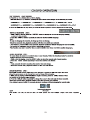
Connection to a Home Theater Audio System
For BEST audio performance
Connecting to a Home Theater System
Dolby Digital can deliver optimal 2 channel
stereo or surround sound with five discrete
full range channels plus a sixth channel for
a subwoofer.
Enjoy optimal sound reproduction from your
system with a Dolby Digital amplifier that
incorporates a digital coaxial input. Connect
an optional digital cable directly to the
television’s Coax audio output to listen
through all inputs except VGA.
(The VGA does not support digital audio)
How To Setup Digital Output
Press the MENU button on the remote control
Press the right ► arrow button to select sound
Press the down ▼ arrow button to highlight
SPDIF type right ► Raw or PCM
Coax
SPDIF OUT
11
Setup
12
6
Tim e
Equalizer Settings
MTS
Audio Language
AVL
Surround Sound
Move Select Exit
MENU
Off
Picture Sound
English
Digital Audio Output PCM
Off
Mono

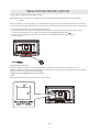
WALL MOUNT INSTALLATION
INSTALLING REMOVING THE BASE STAND
WARNING
/
:The TV Display is very fragile and must be protected at all times when removing the base
Stand
Be sure that no hard or sharp object or anything that could scratch or damage the TV display comes into
contact with it Do NOT exert pressure on the front of the unit at any time because the screen could crack
1 Disconnect all cables or cords connected to the unit
2 Lay the unit down on a flat surface with the back side facing up Please make sure to place a soft
cushioned material such as a pillow or thick piece of foam beneath the screen
3 To remove the base stand loosen screws off the holes then pull downwards to release
the base stand
,
.
. .
. .
. .
. ,
.
MOUNTING ON THE WALL
NOTE
Remove the base stand before mounting the unit on the wall.
This unit is VESA-compliant, and is designed to be wall-mounted with a VESA-compliant 8”x 4”
(200mm x 100mm) mounting kit designed for flat-panel TV's (not supplied). Mount this unit according to
the instructions included in the mounting kit.
Length of screw should not exceed 14 mm.
8”
4”
M5
12

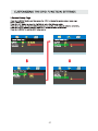
INITIAL SETUP
When you turn on your television set for
the first time, be sure to place it on a solid
stable surface.
To avoid danger, do not expose the TV
to water, or a heat source
(e.g. lamp, candle, radiator).
Do not obstruct the ventilation grid
at the rear and be sure to leave sufficient
gaps around the unit.
PUTTING THE UNIT ON A PROPER PLACE
TURNING THE UNIT ON FOR THE FIRST TIME
After you have initially connected your TV
antenna or cable,
turn the television ON.
A screen will display asking you to run a
to search and receive
available local digital channels.
It is here where you will select antenna options
and run .
Channels will be stored in the TV tuner.
Press the button on the remote control.
Press the button to highlight AIR/CABLE.
Channel Auto Scan
Channel Auto Scan
MENU
Using the buttons, scroll to highlight channel mode.
1. Press the button on the remo te control.
2.
and select any of them using the button or
the button.
ource
Note:
Before wa tching please ma ke sure all necessary
cables and devices are connected.
ENT ER
Use or button to select the optionsthe
(The screen will change to your desired s).
(TV,AV,YPBPR,HDMI1,HDMI2,HDMI3, PC, DVD)
13
Source Select
TV
AV
YPBPR
HDMI1
HDMI2
HDMI3
PC
DVD

14
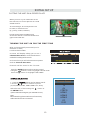
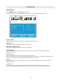
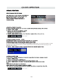
TV SETUP
Press MENU button to display the main menu.
Press ◄ / ► button to select CHANNEL in the main menu,it will highlight the first option.
Setup LOCK
12
6
Tim e
Picture Sound
CHANNEL
Air /Cable
Auto Scan
FavoriteFavorite
Show HideShow Hide
Channel NoumberChannel Noumber
Channel labelChannel label
Channel ListChannel List
Air
Select ExitMove MENU
Move MENU
AIR / CABLE
This feature allows you to switch between air (such as using antenna) and cable.
AUTO SCAN
This feature searches channels automatically for you.
FAVORITES
This feature gives the favorite list of channels added by you.
CHANNEL LIST
This feature shows the list of stored channels.
SHOW / HIDE
This feature tells you if you have chosen for channel to be skipped.
CHANNEL NUMBER
This feature tells you what channel you are currently on.
CHANNEL LABEL
This feature changes the name of the channel.
Please Note:
The channel options are only available when you select TV as your SOURCE.
When you open the OSD menu on other sources (HDMI, AV, Component, PC, Media) these
options will be grayed out.
CHANNEL MENU

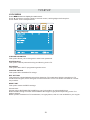
TV SETUP
15
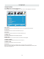
Press MENU button to display the main menu.
Press ◄ / ► button to select PICTURE in the main menu,it will highlight the first option.
PICTURE MODE
This feature changes various color modes for the TV.
BRIGHTNESS
This feature changes the picture's detail in dark colors.
CONTRAST
This feature changes the difference between dark and bright objects.
COLOR
This feature changes the amount of color in the picture.
TINT
This feature changes the white balance of the color.
SHARPNESS
This feature changes the picture quality.
COLOR TEMPERATURE
This feature adjusts the color temperature of the TV, giving warm, normal,
cool.
ADVANCED SETTINGS
a)ASPECT RATIO This feature changes the various aspects of the TV's video.
(Aspects include wide, zoom, cinema,normal).
b)NOISE REDUCTION This feature reduces general pixilation by blurring them.
c)DYNAMIC CONTRAST This feature allows the TV to automatically adjust the contrast of the
TV depending on the picture you are viewing.
PICTURE MENU
Setup
12
6
Tim e
Picture Sound
Picture Mode
Contrast
Brightness
Color
Tint
Sharpness
Color Temperature
Standard
Normal
Move Select Exit
MENU
50
50
50
0
50
Advanced Settings

TV SETUP
16
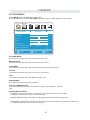
Press MENU button to display the main menu.
Press ◄ / ►button to select SOUND in the main menu,it will highlight the first option.
EQUALIZER SETTINGS
This feature enables the internal equalizer of the speakers.
You can adjust the settings individually or use the presets (standard, music, movie, sports, user).
MTS
This feature adjusts the second audio programming in analog channels.
AUDIO LANGUAGE
This feature adjusts the digital second audio programming in digital channels.
DIGITAL AUDIO OUTPUT
This feature adjusts the digital audio output.
SURROUND SOUND
This feature adjusts the dimensional surround effect on or off (for built-in speakers only).
AVL
This feature adjusts the auto volume leveler enabling volume protection from overly loud
commercials.
SOUND MENU
Setup
12
6
Tim e
Equalizer Settings
MTS
Audio Language
AVL
Surround Sound
Move Select Exit
MENU
Off
Pict ure Sound
English
Digital Audio Output PCM
Off
Mono
Please Note:
AUDIO LANGUAGE and MTS are dependent on the broadcasting station's support and are only
available under the source TV.

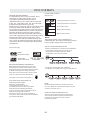
TV SETUP
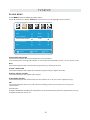
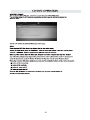
17
Press MENU button to display the main menu.
Press ◄ / ►button to select TIME in the main menu,it will highlight the first option.
TIME MENU
Setup
Sleep Timer
Time Zone
Daylight Saving Time
Clock
Move Select Exit
MENU
Picture
Off
Pacific
Off
1980/01/06 00:00
12
6
Tim e
Sound
Time Format 24-hour
Auto Clock Off
SLEEP TIMER
This timer automatically turns off the TV at the designated time.
TIME ZONE
This option adjusts the global time zone for the TV.
DAYLIGHT SAVING TIME
This option toggles the daylight saving time feature.
TIME FORMAT
This option adjusts the display format for the time.(IE.Under 24 hour format 1PM would
display as 13:00).
AUTO CLOCK
This option enables the TV to sync time with the antenna.
(Put it on AUTO if you have an antenna attached to the TV.If you have CABLE or SATELLITE or
anything else please use make sure AUTO CLOCK is turned off)
CLOCK
This option adjusts the time and date of the TV.You need to disable AUTOCLOCK in order to
use this function.
Please Note:
The TIME function will only keep accurate time if the TV is plugged into a power source.
If the TV is unplugged or the power strip is turned off, the TV's time will not be accurate.
Page is loading ...
Page is loading ...
Page is loading ...
Page is loading ...
Page is loading ...
Page is loading ...
Page is loading ...
Page is loading ...
Page is loading ...
Page is loading ...
Page is loading ...
Page is loading ...
Page is loading ...
Page is loading ...
Page is loading ...
Page is loading ...
Page is loading ...
-
 1
1
-
 2
2
-
 3
3
-
 4
4
-
 5
5
-
 6
6
-
 7
7
-
 8
8
-
 9
9
-
 10
10
-
 11
11
-
 12
12
-
 13
13
-
 14
14
-
 15
15
-
 16
16
-
 17
17
-
 18
18
-
 19
19
-
 20
20
-
 21
21
-
 22
22
-
 23
23
-
 24
24
-
 25
25
-
 26
26
-
 27
27
-
 28
28
-
 29
29
-
 30
30
-
 31
31
-
 32
32
-
 33
33
-
 34
34
-
 35
35
-
 36
36
-
 37
37


Ask a question and I''ll find the answer in the document
Finding information in a document is now easier with AI
Related papers
Other documents
-
Curtis PL4210A User manual
-
-
ProScan PLED4897A User manual
-
-
ProScan PLDED3273A User manual
-
ProScan Proscan PLDV321300 User manual
-
ProScan PLDED3257A-C User manual
-
-
-
Sony KDL-40W3000 Owner's manual