Page is loading ...

Installation Instructions
Instrucciones de Instalación
Chancellor
™
Pressure Balancing Bath and Shower Set
7022.502
Chancellor
™
Juego de Bañera y Regadera con Presión Equilibrada
7022.502
77
8
Remove Plaster Guard and
Assemble Cartridge Cap and
Escutcheon to Valve Body.
Retire la protección de masilla y
ensamble la tapa del cartucho
y el escudete en el cuerpo
de la válvula.
Install Handle, Tighten with
Hex Wrench Supplied. Push in Index Cap.
Instale la manija, apriete con la llave hexagonal provista.
Empuje hacia adentro la tapa índice.
OFF
Recommended Tools
Herramientas Recomendadas
Care and Cleaning:
Do
:
Simply rinse the product clean with clear water, dry with a soft cotton flannel cloth.
Do Not:
Clean the product with soaps, acid, polish, abrasives,
harsh cleaners, or a cloth with a coarse surface.
Para el Cuidado:
Debe:
Lavar el producto sólo con agua limpia, secar con un paño suave de algodón.
No Debe:
Limpiar el producto con jabones, ácido, productos para pulir, abrasivos, limpiadores duros ni con paño grueso.
10'
2
3
6
4
5
3-1/16"
(78mm)
SHR
SHR
SHR
Apply Sealing Tape to
all Threaded Connections.
Thread the four Piping Assemblies
to the Valve Body.
Aplique cinta sellante en todas
las conexiones roscadas.
Enrosque los cuatro ensambles
de la tubería en el cuerpo de
la válvula.
“SHR” Faces Up
“SHR” hacia arriba
1/2" NPT
Threaded Inlets
Entradas Roscadas
1/2" NPT
Inlets
Entradas
1/2" NPT
Tub Port
Orificio de Bañera
1/2" NPT
Shower
Ducha
Finished Wall
Pared Terminada
4"
(102mm)
Top of Tub Rim
Borde Superior de la Bañera
1-7/8" to 3-1/4"
(48mm a 83mm)
18" (457cm)
Optional
Optativa
*5-1/8"
(130mm) REF.
1/2" NPT
1/2" NPT
7-11/16"
(195mm)
3-1/16"
(78mm)
Finished Floor Usually
Between 65" and 78"
(1651 a 1981mm)
Piso Terminado, Por lo
General Entre
65" y 78" (1651 a 1981mm)
Roughing-In Dimensions
Dimensions de Desbastado
4" Min.
4" mín.
Bottom
of Tub
Fondo de la tina
18" Optional
18" opcionales
74" for Head
Clearance
from Bottom
of Tub
74" para el
espacio de la
cabeza desde el
fondo de la tina
Shower Arm
Support
Soporte del brazo
de la ducha
Valve Body
Support
Soporte del cuerpo
de la válvula
Tub Spout
Support
Soporte del
pico de la tina
1
Install Supports for Tub Spout, Valve Body and Shower
Instale los soportes para el pico de la tina, el cuerpo de la válvula y la ducha
Assemble and Solder
All Connections on
Piping Assemblies
Ensamble y suelde todas
las conexiones en los
ensambles de la tubería
1/2" Copper
1/2" Cobre
Apply Sealing Tape to all
Threaded Connections.
Install Shower Arm, Shower
Head and Diverter Spout.
Aplique cinta selladora en
todas las conexiones roscadas.
Instale el brazo de la ducha,
el cabezal de la ducha y
el pico diversor.
Screw Adapter onto
Pipe Connection.
Screw Diverter Spout
onto Adapter.
Atornille el adaptador en la
conexión de la tubería.
Atornille el pico diversor
al adaptador.
Long End
Extremo largo
Turn On Water Supplies and Check all Connections for Leaks.
Turn Off Supplies.Install Plaster Guards and Finish all
Wall Construction.
Abra los suministros de agua y revise todas las conexiones en busca
de fugas. Cierre los suministros. Instale las protecciones de masilla
y termine toda
la construcción
de la pared.
Secure the Bath/Shower Assembly to the Supports
Asegure el ensamble de la tina/ducha en los soportes
Connect Hot and Cold
Water Supplies to
Valve Body
Conecte los suministros
de agua caliente y fría
al cuerpo de la válvula
Hot
Caliente
Cold
Fría
C
H
OFF
C
H
OFF
For use with shower heads rated at 6.8 L/min (1.8 gpm) or higher.
Para uso con cabezales de ducha de 6,8 L / min (1,8 gpm) o superior.
1
5
1
3
1
1
9
7
5
3
1
0
1
5
1
3
1
1
9
7
5
3
1
1
5
1
3
1
1
9
7
5
3
1
COLDER
(Larger Numbers)
MÁS FRÍA
(números mayores)
0 1 3 5 7 9 11 13 15
HOTTER
(Smaller Numbers)
MÁS CALIENTE
(números menores)
0 1 3 5 7 9 11 13 15
1
5
1
5
4
4
3
3
2
2
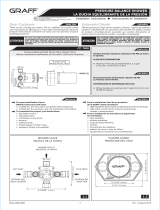
Adjust Hot Limit Stop
By restricting HANDLE rotation and limiting the amount
of hot water allowed to mix with the cold, the HOT
LIMIT STOP (1) reduces risk of accidental scalding.
To set the maximum hot water temperature of your faucet,
all you need to do is adjust the setting on the HOT LIMIT
STOP (1).
Turn CARTRIDGE STEM (2) to the OFF position (coldest setting)
before making adjustment to HOT LIMIT STOP (1). Use a flat
blade screwdriver to pry free the HOT LIMIT STOP (1).
Pull forward and rotate counterclockwise to limit hot water
temperature. Use ARROW (3) on CARTRIDGE (4) and NUMBERS
(5) on HOT LIMIT STOP (1) for indication.
El LIMITADOR DE AGUA CALIENTE (1) restringe la rotación de la
MANIJA y limita la cantidad de agua caliente que puede mezclarse
con el agua fría, reduciendo así el riesgo de quemaduras. Para
especificar la temperatura máxima del agua caliente que sale de la
llave, lo único que tiene que hacer es ajustar el LIMITADOR DE AGUA CALIENTE (1).
Gire el TALLO DEL CARTUCHO (2) a la posición de cierre (OFF, la más fría)
antes de efectuar los ajustes al LIMITADOR DE AGUA CALIENTE (1). Utilice un
destornillador plano para separar el LIMITADOR DE AGUA CALIENTE (1). Tire hacia
fuera y gire en sentido antihorario una posición para limitar la temperatura del
agua caliente. Use la FLECHA (3) del CARTUCHO (4) y los NÚMEROS (5) del
LIMITADOR DE AGUA CALIENTE (1) como indicadores.
Regule el Limitador de Agua Caliente
M965885_SP (12/17)
/