Page is loading ...

Page 1
THIS MANUAL MUST BE LEFT WITH THE
BUILDING OWNER FOR FUTURE REFERENCE
WARNING
Improper installation, adjustment, alteration, service
or maintenance can cause property damage, personal
injury or loss of life. Installation and service must be
performed by a licensed professional HVAC installer or
equivalent, or service agency.
IMPORTANT
The Clean Air Act of 1990 bans the intentional venting of
refrigerant (CFCs, HCFCs and HFCs) as of July 1, 1992.
Approved methods of recovery, recycling or reclaiming
must be followed. Fines and/or incarceration may be
levied for noncompliance.
WARNING
This product contains a chemical known to the State
of California to cause cancer, birth defects, or other
reproductive harm.
CAUTION
As with any mechanical equipment, contact with sharp
sheet metal edges can result in personal injury. Take
care while handling this equipment and wear gloves and
protective clothing.
INSTALLATION
INSTRUCTIONS
HEAT PUMPS
7.5 AND 10 TONS
507744-01
11/2017
Elite Class
™ ELP Series
7.5 and 10 Ton
Shipping and Packing List
Check the unit for shipping damage. If damaged or parts
are missing, immediately contact the last shipping carrier.
1 - Assembled outdoor unit
1 - Installation instructions
Outdoor Unit
ELP Series heat pumps, which will also be referred to in
this instruction as the outdoor unit, uses HFC-410A refrig-
erant. This outdoor unit must be installed with a matching
indoor unit and line set as outlined in the EL Series Engi-
neering Handbook.
This outdoor unit is designed for use in thermal expansion
valve (TXV) systems only.
Table of Contents
Shipping and Packing List .............................................1
Outdoor Unit ..................................................................1
Unit Dimensions, Corner Weights and Centers of Gravity .2
Unit Plumbing Parts Arrangement ..................................3
Model Number Identication ..........................................4
Unit Control Box Components Arrangement ..................4
Rigging the Unit for Lifting .............................................4
Installation Clearances ..................................................5
Line Set .........................................................................5
Electrical Connections ................................................... 5
Refrigerant Charge ........................................................ 9
System Operation ........................................................12
Defrost System ............................................................12
Defrost Control Board ..................................................12
Maintenance ................................................................13

Page 2
Unit Dimensions, Corner Weights and Centers of Gravity
Corner Weights
Model No.AA BB CC DD
lbs. kg lbs. kg lbs. kg lbs. kg
ELP090S4S 108 49 108 49 114 52 114 52
ELP120S4S 120 54 114 52 139 63 149 68
Centers of Gravity
Model No.EE FF
inch mm inch mm
ELP090S4S 21.80 554 29.0 737
ELP120S4S 20.0 508 25.30 643
9−1/8
(232)
(29)
(54)
SUCTION
LINE
LIQUID
LINE
REFRIGERANT LINE
CONNECTIONS DETAIL
(29)
(127)
BASE
REFRIGERANT
LINE CONNECTIONS
SEE DETAIL
DISCHARGE
AIR
41−3/8
60−1/8
(1470)
CONTROL
BOX ACCESS
COMPRESSOR
DISCHARGE
AIR
LIFTING HOLES
(For Rigging)
FRONT VIEW
TOP VIEW
FORKLIFT SLOTS
(Both Sides)
SIDE VIEW
(1108)
48−3/4
(1238)
3−1/2
(89)
(1149)
FF
EE
INLET AIR
INLET AIR
BBAA
CC
DD
CENTER OF
GRAVITY
ELECTRICAL
INLETS (Above
Refrigerant Lines)
OUTDOOR
FAN GUARDS
INLET AIR
BASE
ELECTRICAL
INLETS (Above
Refrigerant Lines)
OPTIONAL HAIL GUARD
(Field Installed All Coil Sides)
(Not used with Coil Guard)
OPTIONAL HAIL GUARD
(Field Installed All Coil Sides)
(Not used with Coil Guard)
OPTIONAL
COIL GUARD
(Field Installed All Coil Sides)
(Not used with Hail Guard)
12
(286)
(Not used with
Hail Guard)
OPTIONAL COIL GUARD
(Field Installed All Coil Sides)
(Not used with Hail Guard)
OPTIONAL
COIL GUARD
(Field Installed
All Coil Sides)
1−1/8
1−1/8
2−1/2
5
57−7/8
(1051)
2 (51)
(1527)
43−5/8
45−1/4

Page 3
Unit Plumbing Parts Arrangement
ELP090S4S
HIGH PRESSURE
SWITCH (S4)
PRESSURE
SWITCH (S192)
LIQUID LINE
BI-FLOW DRIER
LIQUID LINE SERVICE VALVE
SUCTION LINE SERVICE VALVE
LOSS OF CHARGE
SWITCH (S24)
CTXV SENSING BULB
DEFROST SWITCH
LOCATION (S6)
REVERSING
VALVE
CHECK EXPANSION
VALVE (CTXV)
ELP120S4S
HIGH PRESSURE
SWITCH (S4)
PRESSURE
SWITCH (S192)
DEFROST SWITCH
LOCATION (S6)
REVERSING
VALVE
LIQUID LINE
BI-FLOW DRIER
LIQUID LINE SERVICE VALVE
SUCTION LINE SERVICE VALVE
CTXV SENSING BULB
CTXV SENSING BULB
LOSS OF CHARGE
SWITCH (S24)
DEFROST SWITCH
LOCATION (S6)
CHECK EXPANSION
VALVE (CTXV)

Page 4
Model Number Identication
ELPY1120 S N4 S
Brand/Family
Elite™ Product Line
P = Split System Heat Pump
Nominal Cooling Capacity -
Tons
090 = 7.5 Tons
120 = 10 Tons
Cooling Efficiency
S = Standard Efficiency
Minor Design Sequence
1 = 1st Revision
2 = 2nd Revision
3 = 3rd Revision
Voltage
Y = 208/230V‐3 phase‐60hz
G = 460V‐3 phase‐60hz
J = 575V‐3 phase‐60hz
M = 380/420V-3 phase-50hz
Refrigerant Type
4 = R-410A
Refrigerant Circuits
S = Single Circuit
Part Load Capability
N = Single Stage Compressor
Unit Control Box Components Arrangement
ELP090S4S AND ELP120S4S
TRANSFORMER
(T1)
CONTACTOR
(K1)
RUN CAPACITORS
(C1, C2) GROUND LUG
TERMINAL STRIP
(TB14)
DEFROST CONTRO
L
BOARD
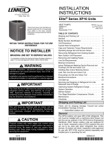
Rigging the Unit for Lifting
Rig the unit for lifting by attaching four cables to the holes
in the base rail of the unit. See gure 1.
1 - Remove protective packaging before rigging the
unit for lifting.
2 - Connect the rigging to the holes in each corner of
the unit’s base.
3 - All panels must be in place for rigging.
4 - Place a eld-provided H-style frame just above the
top edge of the unit. The frame must be of adequate
strength and length. (An H-style frame will prevent
the top of the unit from being damaged.)

Page 5
Caution - do not
walk on unit.
Lifting point should be directly above the center of gravity.
Important - all panels
must be in place for
rigging.
FIGURE 1. ELP090S4S and ELP120S4S
Installation Clearances
See Unit Dimensions on page 2 for sizing mounting slab,
platforms or supports. Refer to gures 4 through 6 for
mandatory installation clearance requirements.
NOTES:
• Clearance to one of the remaining two sides may be 12
in. (305 mm) and the nal side may be 6 in. (152 mm).
• A clearance of 24 in. (610 mm) must be maintained be-
tween two units.
• 48 in. (1219 mm) clearance required on top of unit.
CONTROL BOX
ACCESS
SEE
NOTES
SEE
NOTES
36”
30”
FIGURE 2. ELP090S4S and ELP120S4S
Installation Clearances
Line Set
Field refrigerant piping consists of liquid and suction lines
connecting the condensing unit and the indoor unit. Liquid
and suction service valves are located in a compartment
at the corner of the unit below the control box.
Piping can be routed directly from the service valves or
eld supplied elbows can be added to divert the piping as
required.
Refer to table 1 for eld-fabricated refrigerant line sizes for
runs up to 50 linear feet (15 m).
TABLE 1. Refrigerant Line Sizes for Runs
Up to 50 Linear Feet
Unit Liquid Line Suction Line
ELP090 5/8” (16mm) 1-1/8” (29mm)
ELP120 5/8" (16mm) 1-1/8” (29mm)
Refrigerant Line Limitations
You may install the unit in applications that have line set
lengths of up to 50 linear feet (15 m) with refrigerant line
sizes as outlined in table 1 (excluding equivalent length of
ttings). Size refrigerant lines greater than 50 linear feet
(15m or greater) according to the Lennox Refrigerant Pip-
ing Design and Fabrication Guidelines (Corp. 9351-L9) or
latest version.
Electrical Connections
WARNING
Electric Shock Hazard. Can cause injury or
death. Unit must be properly grounded in
accordance with national and local codes.
Line voltage is present at all components
when unit is not in operation on units with
single-pole contactors. Disconnect all remote
electric power supplies before opening
access panel. Unit may have multiple power
supplies.
In the United States, wiring must conform with current lo-
cal codes and the current National Electric Code (NEC). In
Canada, wiring must conform with current local codes and
the current Canadian Electrical Code (CEC).
TRANSFORMER – 24VAC, 70VA – PROVIDED
NOTE – The addition of accessories to the system could
exceed the 70VA power requirement of the factory-pro-
vided transformer. Measure the system’s current and
voltage after installation is complete to determine trans-
former loading. If loading exceeds the factory-provided
transformer capacity, a larger eld-provided transformer
will need to be installed in the system.

Page 6
Refer to the unit nameplate for minimum circuit ampacity amperage
minimum, and maximum fuse or circuit breaker fusible (HACR per
NEC). Install power wiring and properly sized disconnect switch.
NOTE — UNITS ARE APPROVED FOR USE ONLY WITH COPPER
CONDUCTORS. GROUND UNIT AT DISCONNECT SWITCH OR TO AN EARTH
GROUND.
CIRCUIT SIZING AND DISCONNECT SWITCH
DISCONNECT
SWITCH
MAIN FUSE
BOX/BREAKER
PANEL
1
K1 CONTACTOR
LEFT CUTOUT
HIGH VOLTAGE WIRING
GROUND LUG
CONTROL BOX
USE THE LEFT CUTOUT TO ROUTE
HIGH VOLTAGE WIRING TO THE K1
CONTACTOR ON THE ELP090S AND
120S MODELS.
NOTE - ANY EXCESS HIGH VOLTAGE
FIELD WIRING SHOULD BE TRIMMED
AND SECURED AWAY FROM ANY LO
W
VOLTAGE FIELD WIRING.
ROUTE EARTH GROUND THROUGH
LEFT CUTOUT AND CONNECT TO
GROUND LUG.
2
TYPICAL HIGH VOLTAGE POWER SUPPLY
CONNECTIONS
Install room thermostat (ordered separately) on an inside wall
approximately in the center of the conditioned area and 5 feet (1.5m)
from the floor. It should not be installed on an outside wall or where it
can be affected by sunlight, drafts or vibrations.
THERMOSTAT
5 FEET
(1.5M)
INSTALL THERMOSTAT
3
Install low voltage wiring from outdoor to indoor unit and from
thermostat to indoor unit as illustrated.
TYPICAL CONTROL WIRING
ELP HEAT
PUMP
C1
W1
C
R
C1
C
RO
ELA AIR
HANDER
Y1
C
R
A2
THERMOSTAT
RT2 REMOTE
SENSOR
S2
S1
W2
W
W2
W1
W2
4

Page 7
TYPICAL UNIT CONTROL WIRE CONNECTIONS
5
WIRE RUN LENGTH AWG# INSULATION TYPE
LESS THAN 100’ (30M) 18 TEMPERATURE RATING
MORE THAN 100’ (30M) 16 35°C MINIMUM
ARUN CONTROL WIRES THROUGH RIGHT CUTOUT.
B RUN CONTROL WIRES THROUGH WIRE TIES.
MAKE CONTROL WIRE CONNECTIONS USING FIELD
PROVIDED WIRE NUTS. SEE FIGURE 3 FOR CONNECTION
REQUIREMENTS.
C
DTIGHTEN WIRE TIE TO SECURE 24VDC CONTROL WIRING.
NOTE - FOR PROPER VOLTAGES, SELECT THERMOSTAT WIRE (CONTROL
WIRING) GAUGE PER TABLE ABOVE.
NOTE - WIRE TIE PROVIDES LOW VOLTAGE WIRE STRAIN RELIEF AND
MAINTAINS SEPARATION OF FIELD INSTALLED LOW AND HIGH VOLTAGE
CIRCUITS.
NOTE - DO NOT BUNDLE ANY EXCESS 24VAC CONTROL WIRES INSIDE
CONTROL BOX.
K1
CONT
ACTOR
CONTROL BOX
ROUTE THROUGH
WIRE TIES
LOW VOLTAGE
CONTROL WIRING
ROUTE EARTH GROUND
THROUGH LEFT CUTOUT
AND CONNECT TO
GROUND LUG.
HIGH VOLTAGE
WIRING
RIGHT CUTOUT
TIGHTEN
WIRE TIES
C
D
A
B

Page 8
DENOTES OPTIONAL COMPONENTS
LINE VOLTAGE, FIELD INSTALLED
K1
FAN
O OUT
LO-PS
DF
Y1 OUT
K3
HI PS
P45
Y1ORC
DF
PS
TST
K2
K2
S24
W1
C
L
R
O
Y1
COM
24
CMC1
P45
S24 SWITCH-LOSS OF CHARGE COMP 1
PLUG-INPUT
IF ANY WIRE IN THIS APPLIANCE IS REPLACED,
IT MUST BE REPLACED WITH WIRE OF LIKE SIZE,
RATING,INSULATION THICKNESS AND TERMINATION
537912-02
B5
WARNING-ELECTRIC SHOCK HAZARD, CAN CAUSE
INJURY OR DEATH, UNIT MUST BE GROUNDED IN
ACCORDANCE WITH NATIONAL AND LOCAL CODES
DISCONNECT ALL POWER BEFORE SERVICING
7
C2
C2
B5 MOTOR-OUTDOOR FAN 2
CAPACITOR-OUTDOOR FAN 2
1
4
K10,-1
2
1
K8-1
2
85
K8-2
CB8 CIRCUIT BREAKER-TRANS T1
S9
T1 TRANSFORMER-CONTROL
SWITCH-DEFROST,COMPRESSOR 2
SWITCH-DEFROST,COMPRESSOR 1
T1
CB8
208V
240 / 460 / 575V
400V
HEAT 1
HEAT 2
COOL 1
H1
H2
C1
1
S9
SECTION A5
WIRING DIAGRAM
B
A
ELP-090,120-G,J,M,Y WITH 2 SPD
COMP PROTECTION
J36
2
31
2
31
6
2S9 IS USED ON ELP120 ONLY
2
3FOR USE WITH COPPER CONDUCTORS ONLY
3
2011
09/17
L34
7
4
K67-1
69
3
COOL 2
C2
DUAL SPEED COMPRESSOR
L34
K48
II
REV. 0
4
1
S192
K48
K67,-1
SWITCH, LIMIT HI PRESS CHANGEOVER COMP 1
FIGURE 3. Typical Wiring Diagram – ELP090S4S and ELP120S4S (G, J, Y, M Voltages)

Page 9
Refrigerant Charge
ELP units have a factory holding charge of 2 pounds of
HFC-410A. Additional refrigerant will need to be added
during installation (table 2).
TABLE 2. Adding Refrigerant
Models 25 Feet1
(pounds
Liquid
Line
Dia.
(inches)
Vapor
Line
Dia.
(inches)
Ounces
Adjustment
per foot of
line set2
ELP090 /
ELA090
23.25 5/8 1-1/8 1.7
ELP120 /
ELA120
31.0 5/8 1-1/8 1.7
1Total amount of charge necessary to accommodate 25
feet of line set.
2If line set length is greater than 25 feet, add this amount
to each circuit. If line set is less than 25 feet, subtract this
amount from each circuit. Refer to Lennox Refrigerant
Piping Design and Fabrication Guidelines for more infor-
mation.
NOTE - Refrigerant line sets longer than 200 feet (60 me-
ters) are not recommended. For assistance contact Len-
nox Application Department.
To charge the system, use either of the following proce-
dures:
CHARGE PROCEDURE – NORMAL OPERATING
PRESSURES
1 - Connect a manifold gauge set to the service valves:
A - Low pressure gauge to vapor service port.
B - High pressure gauge to liquid valve service port
2 - Operate system in cooling mode until pressures
and temperatures stabilize (5 minutes minimum).
3 - Use a thermometer to measure the outdoor
ambient temperature. The outdoor temperature will
determine which charging procedure to use.
Outdoor Temp > 65ºF (18ºC)
1 - Apply the outdoor ambient temperature to table
4 or 5 to determine normal operating pressures.
Compare the normal operating pressures to the
pressures obtained from the connected gauges.
If discharge pressure is high, remove refrigerant
from the system. If discharge pressure is low, add
refrigerant to the system.
A - Add or remove charge in increments.
B - Allow the system to stabilize at least 5 minutes each
time refrigerant is added or removed
2 - Minor variations in these pressures may be
expected due to differences in installations.
Signicant differences could mean that the system
is not properly charged or that a problem exists with
some component in the system.
3 - Switch to heating mode to conrm normal operating
pressures. Let the system stabilize at least 10
minutes, then compare the pressure obtained from
the connected gauges to the normal operating
pressures (heating mode) in table 5.
4 - Verify the charge, as described in the approach
method section.
Outdoor Temp < 65ºF (18ºC)
1 - When the outdoor ambient temperature is below
65F (18C) it may be necessary to restrict the air ow
through the outdoor coil to achieve liquid pressures
in the 325-375 psig (2240-2585 kPa) range. These
higher pressures are necessary for checking the
charge. Block equal sections of the outdoor coil on
all coil sides until the liquid pressure is in the 325-
375 psig range (gure 4).
2 - Charge the unit using the approach method in the
approach method section.
3 - Switch to heating mode and let the system stabilize
at least 10 minutes. Then conrm that the pressures
obtained from the connected gauges match the
normal operating pressures (heating mode) in table 5.
4 - Minor variations in these pressures may be
expected due to differences in installations.
Signicant differences could mean that the system
is not properly charged or that a problem exists with
some component in the system.
CARDBOARD OR
PLASTIC SHEET
OUTDOOR
COIL SHOULD BE BLOCKED ONE SIDE AT A TIME
WIT
H CARDBOARD OR PLASTIC SHEET UNTIL PROPER
TESTIN
G PRESSURES ARE REACHED.
FIGURE 4. Blocking Outdoor Coil
CHARGE PROCEDURE – APPROACH METHOD
Use the following approach method along with the normal
operating pressures to conrm readings.
1 - Using the same thermometer, compare liquid
temperature at service valve to outdoor ambient
temperature.
Approach Temperature = Liquid temperature minus
ambient temperature

Page 10
2 - Approach temperature should be as indicated in
table 3 for each stage. An approach temperature
greater than this value indicates an undercharge.
An approach temperature less than this value
indicates an overcharge.
A - Add or remove charge in increments.
B - Allow system to stabilize at least 5 minutes each
time refrigerant is added or removed.
3 - Do not use the approach method if system pressures
do not match pressures in table 4 except when the
outdoor ambient temperature is below 65ºF (18ºC).
The approach method is not valid for grossly over or
undercharged systems.
TABLE 3. HFC-410A Approach Temperatures*
Models
Approach
Temperature (ºF)
(+/-1)
Approach
Temperature (ºC)
(+/-.05)
ELP090S4S /
ELA090 7.0 3.9
ELP120S4S /
ELA120 6.0 3.3
*Approach temperature method valid at full load.
TABLE 4. HFC-410A Normal Operating Pressures – Cooling Mode (Liquid ±10 and Suction ±5 psig)**
Temp* ELP090 / ELA090 ELP120 / ELA120
Liquid Suction Liquid Suction
65º F (18º C) 226 119 247 132
75º F (24º C) 261 125 291 136
85º F (29º C) 303 129 333 138
95º F (35º C) 349 133 370 140
105º F (41º C) 404 135 437 142
115º F (46º C) 462 137 495 144
125º F (52º C) 525 136 562 146
STD. CFM 2760 4000
*Temperature of air entering outdoor coil.
Liquid and suction pressures measured via condenser service valve ports.
** Indoor conditions – 80° F Dry Bulb and 67° F Wet Bulb.
TABLE 5. HFC-410A Normal Operating Pressures – Heating Mode (Liquid ±10 and Suction ±5 psig)**
Temp* ELP090 / ELA090 ELP120 / ELA120
Liquid Suction Liquid Suction
60º F (15º C) 364 121 335 115
50º F (10º C) 343 100 322 101
40º F (4º C) 324 83 308 86
30º F (-1º C) 311 72 294 72
20º F (-6º C) 297 57 280 58
10º F (-12º C) 280 44 266 44
STD. CFM 2760 4000
*Temperature of air entering outdoor coil.
Liquid and suction pressures measured via condenser service valve ports.
** Indoor conditions – 70° F.

Page 11
TABLE 6. HFC-410A Temperature (ºF) – Pressure (Psig)
°F Psig °F Psig °F Psig °F Psig °F Psig °F Psig °F Psig °F Psig
32 100.8 48 137.1 63 178.5 79 231.6 94 290.8 110 365.0 125 445.9 141 545.6
33 102.9 49 139.6 64 181.6 80 235.3 95 295.1 111 370.0 126 451.8 142 552.3
34 105.0 50 142.2 65 184.3 81 239.0 96 299.4 112 375.1 127 457.6 143 559.1
35 107.1 51 144.8 66 187.7 82 242.7 97 303.8 113 380.2 128 463.5 144 565.9
36 109.2 52 147.4 67 190.9 83 246.5 98 308.2 114 385.4 129 469.5 145 572.8
37 111.4 53 150.1 68 194.1 84 250.3 99 312.7 115 390.7 130 475.6 146 579.8
38 113.6 54 152.8 69 197.3 85 254.1 100 317.2 116 396.0 131 481.6 147 586.8
39 115.8 55 155.5 70 200.6 86 258.0 101 321.8 117 401.3 132 487.8 148 593.8
40 118.0 56 158.2 71 203.9 87 262.0 102 326.4 118 406.7 133 494.0 149 601.0
41 120.3 57 161.0 72 207.2 88 266.0 103 331.0 119 412.2 134 500.2 150 608.1
42 122.6 58 163.9 73 210.6 89 270.0 104 335.7 120 417.7 135 506.5 151 615.4
43 125.0 59 166.7 74 214.0 90 274.1 105 340.5 121 423.2 136 512.9 152 622.7
44 127.3 60 169.6 75 217.4 91 278.2 106 345.3 122 428.8 137 519.3 153 630.1
45 129.7 61 172.6 76 220.9 92 282.3 107 350.1 123 434.5 138 525.8 154 637.5
46 132.2 62 175.4 77 224.4 93 286.5 108 355.0 124 440.2 139 532.4 155 645.0
47 134.6 78 228.0 109 360.0 140 539.0

Page 12
System Operation
The outdoor unit and indoor blower cycle on demand from
the room thermostat. When the thermostat blower switch
is in the ON position, the indoor blower operates contin-
uously.
HIGH PRESSURE SWITCHES (S4 AND S7)
These units are equipped with an auto-reset high pressure
switch (single-pole, single-throw) which is located on the
discharge line. The switch shuts off the compressor when
discharge pressure rises above the factory setting. High
Pressure (auto reset) – trip at 640 psig; reset at 512 psig.
LOSS OF CHARGE SWITCH (S24)
These units are equipped with a loss-of-charge switch that
is located in the liquid line. The switch is a SPST, auto-re-
set switch that is normally closed. The switch opens at 40
psi and closes at 90 psi.
Defrost System
The defrost system includes a defrost thermostat and a
defrost control.
DEFROST THERMOSTAT
The defrost thermostat is located on the liquid line between
the check/expansion valve and the distributor on each
coil. When the defrost thermostat senses 42°F (5.5°C) or
cooler, its contacts close and send a signal to the defrost
control board to start the defrost timing. It also terminates
defrost when the liquid line warms up to 70°F (21°C).
DEFROST CONTROL
The defrost control board includes the combined functions
of a time/temperature defrost control, defrost relay, time
delay, diagnostic LEDs, and a terminal strip for eld wiring
connections.
The control provides automatic switching from normal
heating operation to defrost mode and back. During com-
pressor cycle (defrost thermostat is closed, calling for de-
frost), the control accumulates compressor run times at
30, 60, or 90 minute eld adjustable intervals. If the de-
frost thermostat is closed when the selected compressor
run time interval ends, the defrost relay is energized and
defrost begins.
Each timing pin selection provides a different accumulat-
ed compressor run time period for one defrost cycle. This
time period must occur before a defrost cycle is initiated.
The defrost interval can be adjusted to 30 (T1), 60 (T2), or
90 (T3) minutes. The maximum defrost period is 14 min-
utes and cannot be adjusted.
NOTE — Defrost control part number is listed near the P1
timing pins.
• Units with defrost control 100269-02: The factory de-
fault defrost interval is 60 minutes.
• Units with defrost control 100269-04 or higher: The fac-
tory default defrost interval is 90 minutes.
If the timing selector jumper is missing, the defrost control
defaults to a 90-minute defrost interval.
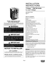
Defrost Control Board
DEFROST CONTROL TIMING PINS
24V TERMINAL
STRIP
CONNECTIONS
DIAGNOSTIC
LEDS
HIGH PRESSURE
SWITCH
TEST
PINS
FIELD SELECT
TIMING PINS
REVERSING
VALVE
DEFROST
THERMOSTAT
LOSS-OF-CHARGE
SWITCH
COMPRESSOR
DELAY PINS
S4
S24
SERVICE LIGHT
CONNECTIONS
FIGURE 5. Outdoor Unit Defrost Control Board
A TEST option is provided for troubleshooting. The TEST
mode may be started any time the unit is operating in the
heating mode and the defrost thermostat is closed or jum-
pered. If the jumper is in the TEST position at power-up,
the control will ignore the test pins. When the jumper is
placed across the TEST pins for two seconds, the con-
trol will enter the defrost mode. If the jumper is removed
before an additional 5-second period has elapsed (7 sec-
onds total), the unit will remain in defrost mode until the
defrost thermostat opens or 14 minutes have passed. If
the jumper is not removed until after the additional 5-sec-
ond period has elapsed, the defrost will terminate and the
test option will not function again until the jumper is re-
moved and re-applied.
COMPRESSOR DELAY
The defrost board has a eld-selectable function to reduce
occasional sounds that may occur while the unit is cycling
in and out of the defrost mode. When the compressor de-
lay jumper is removed, the compressor will be cycled off
for 30 seconds going in and out of the defrost mode.
NOTE – The 30-second compressor feature is ignored
when the TEST pins have been jumpered.
TIME DELAY
The timed-off delay is ve minutes long. The delay helps
protect the compressor from short-cycling in case the
power to the unit is interrupted or a pressure switch opens.
The delay is bypassed by placing the timer select jumper
across the TEST pins for 0.5 seconds.
NOTE – The board must have a thermostat demand for
the bypass function.
PRESSURE SWITCH CIRCUITS
The defrost control includes two pressure switch circuits.
The factory-installed high pressure switch (S4) wires are
connected to the board’s HI PS terminals (gure 5). The
board also includes LO PS terminals to accommodate the
factory installed loss-of-charge switch.

Page 13
During a single thermostat cycle, the defrost control will
lock out the unit after the fth time that the circuit is in-
terrupted by any pressure switch that is wired to the con-
trol board. In addition, the diagnostic LEDs will indicate
a pressure switch lockout after the fth occurrence of an
open pressure switch (table 7). The unit will remain locked
out until power is broken then remade to the control or un-
til the jumper is applied to the TEST pins for 0.5 seconds.
NOTE – The defrost control board ignores input from the
loss-of-charge switch terminals during the TEST mode,
during the defrost cycle, during the 90-second start-up
period, and for the rst 90 seconds each time the revers-
ing valve switches heat/cool modes. If the TEST pins are
jumpered and the 5-minute delay is being bypassed,
the LO PS terminal signal is not ignored during the
90-second start-up period.
SERVICE LIGHT CONNECTION
The defrost control board includes terminal connections
for a service light which provides a signal that activates
the room thermostat service light during periods of inef-
cient operation.
IMPORTANT
After testing has been completed, properly reposition
test jumper across desired timing pins.
DIAGNOSTIC LEDS
The defrost board uses two LEDs for diagnostics. The
LEDs ash a specic sequence according to the diagno-
sis (table 7).
TABLE 7. Defrost Control Board Diagnostic LEDs
DS2 Green DS1 Red Condition
OFF OFF Power problem
Simultaneous Slow Flash Normal operation
Alternating Slow Flash5-min. anti-short cycle delay
Fault and Lockout Codes
OFF Slow FlashLoss-of-Charge Fault
OFF ON Loss-of-Charge Lockout
Slow Flash OFF High Pressure Fault
ON OFF High Pressure Lockout
Maintenance
At the beginning of each cooling season, the system
should be checked as follows:
OUTDOOR UNIT
1 - Clean and inspect the condenser coil. You can ush
the coil with a water hose.
2 - The outdoor fan motor is prelubricated and sealed.
No further lubrication is necessary.
3 - Visually inspect connecting lines and coils for
evidence of oil leaks.
4 - Check wiring for loose connections.
5 - Check for correct voltage at the unit while the unit is
operating and while it is off.
6 - Check amp-draw of the outdoor fan motor.
Unit nameplate _________ Actual ____________
7 - Check amp-draw of the compressor.
Unit nameplate _________ Actual ____________
NOTE — If the owner complains of insufcient cooling,
gauge the unit and check the refrigerant charge. Refer to
section on refrigerant charging in this instruction.
INDOOR COIL
1 - If necessary, clean the coil.
2 - Check connecting lines and coils for evidence of oil
leaks.
3 - If necessary, check the condensate line and clean it.
INDOOR UNIT
1 - Clean or change lters.
2 - Adjust the blower speed for cooling. Measure the
pressure drop over the coil to determine the correct
blower CFM. Refer to the unit information service
manual for pressure drop tables and procedure.
3 - On belt drive blowers, check the belt for wear and
proper tension.
4 - Check all wiring for loose connections.
5 - Check for correct voltage at the unit (blower
operating).
6 - Check amp-draw on blower motor.
Unit nameplate _________ Actual ____________

Page 14
Start-Up and Performance Checklist
Job Name Job no. Date
Job Location City State
Installer City State
Unit Model No. Serial No. Service Technician
Nameplate Voltage
Rated Load Ampacity Compressor Amperage:
Maximum Fuse or Circuit Breaker
Electrical Connections Tight? Indoor Filter clean? Supply Voltage (Unit Off)
Indoor Blower RPM S.P. Drop Over Indoor (Dry) Outdoor Coil Entering Air Te mp.
Vapor Pressure;
Refrigerant Lines: Leak Checked? Properly Insulated? Outdoor Fan Checked?
Service Valves: Fully Opened? Caps Tight? Voltage With Compressor Operating
SEQUENCE OF OPERATION
Calibrated?
THERMOSTAT
Properly Set? Level?
Heating Correct? Cooling Correct?
/