Page is loading ...

BlueWave
®
AX-550 Flood System User Guide
Compact Large-Area LED System
▪ Instructions for Safe Use
▪ Setup and Operation
▪ Maintenance
▪ Ordering Spare Parts and Accessories

BlueWave® AX-550 LED Flood Curing System User Guide
2
About Dymax
UV/Visible light-curable adhesives. Systems for light curing, fluid dispensing, and fluid packaging.
Dymax manufactures industrial adhesives, light-curable adhesives, epoxy resins, cyanoacrylates, and activator-cured adhesives. We also
manufacture a complete line of manual fluid dispensing systems, automatic fluid dispensing systems, and light-curing systems. Light-curing
systems include UV broad-spectrum and LED curing sources configured in, spot, flood, and conveyor systems designed for compatibility and
high performance with Dymax adhesives.
Dymax adhesives and light-curing systems optimize the speed of automated assembly, allow for 100% in-line inspection, and increase
throughput. System designs enable stand-alone configuration or integration into your existing assembly line.
Please note that most dispensing and curing system applications are unique. Dymax does not warrant the fitness of the product for the
intended application. Any warranty applicable to the product, its application, and use is strictly limited to that contained in the Dymax standard
Conditions of Sale. Dymax recommends that any intended application be evaluated and tested by the user to ensure that desired performance
criteria are satisfied. Dymax is willing to assist users in their performance testing and evaluation by offering equipment trial rental and leasing
programs to assist in such testing and evaluations.

3
BlueWave® AX-550 LED Flood Curing System User Guide
Contents
Introduction .................................................................................................................................................... 4
Intended Audience ........................................................................................................................................ 4
Where to Get Help ........................................................................................................................................ 4
Safety ............................................................................................................................................................. 4
Product Overview ........................................................................................................................................... 5
Description of BlueWave
®
AX-550 LED Flood Curing System ........................................................................ 5
Unpacking ....................................................................................................................................................... 6
Unpacking and Inspecting Your Shipment .................................................................................................... 6
Parts Included ............................................................................................................................................... 6
System Installation ......................................................................................................................................... 7
System Assembly........................................................................................................................................... 7
System Cooling .............................................................................................................................................. 7
Wiring and Connections ................................................................................................................................ 8
Connections .................................................................................................................................................. 9
PLC UV Control ............................................................................................................................................. 13
Status Output .............................................................................................................................................. 14
Operation ..................................................................................................................................................... 14
Rotary Push Button ..................................................................................................................................... 15
System Initializing ....................................................................................................................................... 16
System Settings ........................................................................................................................................... 17
Irradiation Setup ......................................................................................................................................... 22
Irradiation in Production or Admin Mode................................................................................................... 24
Irradiation in PLC mode ............................................................................................................................... 25
Maintenance ................................................................................................................................................ 26
Product Cleaning ......................................................................................................................................... 26
Emitter Replacement .................................................................................................................................. 26
Replace Fuse ............................................................................................................................................... 27
Troubleshooting ........................................................................................................................................... 28
Error Screen ................................................................................................................................................ 28
Spare Parts & Accessories ............................................................................................................................. 30
Accessories .................................................................................................................................................. 30
Components & Spare Parts ......................................................................................................................... 30
Specifications ................................................................................................................................................ 31
Validation ..................................................................................................................................................... 33
Set Exposure Time, Determine Intensity..................................................................................................... 33
Set Intensity, Determine Exposure Time..................................................................................................... 33
Control ........................................................................................................................................................ 33
Warranty ...................................................................................................................................................... 33

BlueWave® AX-550 LED Flood Curing System User Guide
4
Introduction
This guide describes how to set up, use, and maintain BlueWave® AX-550 LED Flood Curing System safely and
efficiently.
Intended Audience
This user guide is meant for experienced process engineers, technicians, and manufacturing personnel. If you are
new to high-intensity LED light sources and do not understand the instructions, contact Dymax Application
Engineering for answers to your questions before using the equipment.
Where to Get Help
Dymax Customer Support and Application Engineering teams are available by phone in the United States, Monday
through Friday, from 8:00 a.m. to 5:30 p.m. Eastern Standard Time. You can also email Dymax at [email protected].
Contact information for additional Dymax locations can be found on the back cover of this user guide.
Additional resources are available to ensure a trouble-free experience with our products:
▪ Detailed product information on our website www.dymax.com
▪ Dymax adhesive product data sheets on our website
▪ Safety data sheets (SDS) provided with shipments of Dymax materials
Safety
WARNING! If you use this UV light source without first reading and understanding the information in
the UV Light Safety Guide, SAF001, injury can result from exposure to high-intensity light. To reduce the
risk of injury, please read and ensure you understand the information in that guide before assembling
and operating the Dymax UV LED light source.
This device falls under IEC 62471 Risk Group 3 for UVA and Blue Light emissions:
WARNING. UV emitted from this product. Avoid eye and skin exposure to unshielded products.
WARNING. Possibly hazardous optical radiation emitted from this product. Do not look at operating
lamp. Eye injury may result.

5
BlueWave® AX-550 LED Flood Curing System User Guide
Product Overview
Description of BlueWave
®
AX-550 LED Flood Curing System
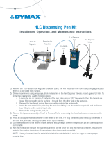
The BlueWave® AX-550 is a high-intensity LED flood system used for curing light-curable materials. The unit is
designed to be integrated into a larger system, such as an automated manufacturing system, or used with a light
shielding enclosure to create a bench-top curing station.
The BlueWave® AX-550 is a single component system that incorporates an LED flood emitter and control system
for manual and automated process applications. Dymax offers three different wavelength LED flood emitters:
VisiCure® (405 nm), PrimeCure® (385 nm), and RediCure® (365 nm).
The controller portion includes the controller and power supply, which is designed to identify the type of emitter
that is connected so the control portion of the system can be used with any of the three LED emitter
configurations.
The BlueWave® AX-550 functions as a flood-curing system with a 125 mm x 125 mm (5 in x 5 in) irradiated curing
area.
The unit can be operated in admin mode
(unrestricted control) or production mode (restricted
control) which allows for process management via
access restrictions.
The unit can be controlled as well by Programmable
Logic Controller (PLC) for automation applications.
LED technology within the BlueWave® AX-550 LED
Flood System allows for instant on/off activation
without the need for a warm-up period, but is also
rated for continuous operation.
Fans in the emitter provide cooling air flow. The vents
on the top and side of the system must not be
covered or blocked, refer to the section “System
Coolingfor details.
There are thermal sensors in the controller and
emitter to protect the system if the internal
temperature exceeds maximum limits.
Figure 1. AX-550 LED Flood Curing System

BlueWave® AX-550 LED Flood Curing System User Guide
6
Unpacking
Unpacking and Inspecting Your Shipment
Upon arrival, inspect all boxes for damage and notify the shipper of box damage immediately. Open each box and
check for equipment damage. If parts are damaged, notify the shipper and submit a claim for the damaged parts.
Contact Dymax so that new parts can be shipped to you immediately.
The parts below are included in every package/order. If parts are missing from your order, contact your local
Dymax representative or Dymax Customer Support to resolve the problem.
Inspect the glass for any damage or residue on the surface. Carefully clean the glass with the alcohol swab. Take
care not to touch the glass with bare hands, as any residue left on the window can adversely affect performance
on the unit.
Parts Included
▪ BlueWave® AX-550 Controller
▪ BlueWave® AX-550 Emitter (RediCure®, PrimeCure®, or
VisiCure®, model as selected at time of purchase)
▪ Power Cord
▪ BlueWave® AX-550 LED Flood System User Guide
(document not shown)
▪ Terminal Block (Plugged on the BlueWave® AX-550 Controller)
▪ Foot Pedal
▪ Safety Eyewear
Figure 2. System Packaging
Figure 3. Components of the BlueWave® AX-550 Curing System
Controller Packaging
Emitter Packaging
Foot Pedal (CE Compliant)

7
BlueWave® AX-550 LED Flood Curing System User Guide
System Installation
System Assembly
The system includes two major parts, the Controller and the Emitter. The two parts are shipped separately. To
assemble the two parts together, please follow the instruction below:
1. Locate the 4 Screws to be used to assemble the Emitter to the Controller.
2. Carefully place the Emitter on a clean and flat surface. Align the Controller and the Emitter as shown in Figure 4.
Plug the Controller into the Emitter.
Note: Be careful to keep the glass at the bottom of the Emitter clean. To avoid leaving finger prints on the glass,
do not touch the glass with bare hands.
3. Install the 4 Screws to secure the Emitter to the Controller.
Figure 4. Align Controller and Emitter
Figure 5. Install 4 Screws
System Cooling
The system can be used in various scenarios with
additional mounting fixtures or Dymax accessories.
For example: on a desktop with a Dymax stand, on a
chamber, conveyer, etc. This system should only be
operated in a location that provides proper cooling.
Location requirements are as follows:
▪ For proper cooling of the unit, upper intake
and lower exhaust must not be blocked.
▪ Minimum clearance as shown in Figure 6.
Figure 6. Minimum Clearance
Intake requires
1" vertical clearance
Minimum of one side
open with 1" clearance

BlueWave® AX-550 LED Flood Curing System User Guide
8
Wiring and Connections
All the wire and cable connections are at the top side of the controller.
Figure 7. Controller, Topside
Power Input: The power cord plugs in here.
Power Switch: Turns the unit on and off.
I/O Interface: Reference connector pin-out on the back of the controller (Figure 8).
PLC Connector: Terminal block for all wiring of remote control features including foot pedal, inhibit/interlock,
PLC and status display.
Figure 8. PLC Connector Pin Reference
I/O Interface with
Terminal Block installed
Power Input
Power Switch

9
BlueWave® AX-550 LED Flood Curing System User Guide
Connections
An 18-pin removable terminal block (the green part in the photos below) comes with the controller. The terminal
block allows quick and easy wiring. The terminal block can fit the wire from AWG 24 to AWG 16.
▪ To connect a hard wire to the terminal block (such as the foot pedal terminals): Plug the end of the wire
into the terminal (Figure 9).
▪ To connect a soft wire to the terminal block or pull out the wire from the terminal block: Use a flat
screw driver to push the orange tab located beside the terminal. Then plug the wire in or pull the wire out
(Figure 10).
Figure 9. Insert Hard Wire into Terminal
Block
Figure 10. Insert Soft Wire or Pull Wire Out
of Terminal Block
▪ To remove the jumper from the terminal block: Use two flat screw drivers to simultaneously push the
orange tabs located beside the terminal. Then pull the jumper out. (
▪ Figure 11)
Figure 11. Remove Jumper from Terminal Block

BlueWave® AX-550 LED Flood Curing System User Guide
10
I/O Interface Summary
Table 1 below shows the summary of all signals on the PLC Connector.
Table 1. I/O Interface
Signal Name / Description
Isolated Inputs/
outputs
Connector
-Pin
Signal Level
Asserted
De-Asserted
I/O Inputs
Reserved
1
Do Not Use
Reserved
2
Reserved
9
Analog Intensity
Only used in PLC – EXT mode
Sets Emitter intensity level (0~1V=10% output, 10V=100% output)
Input Impedance: 10KΩ
IN
3
0 – 10 VDC
N/A
Master Interlock
Input Current: 0 – 7mA
IN
5
0 VDC, GND
(Open)
PLC Enable
Input Current: 0 – 7mA
IN
12
0 VDC, GND
(Open)
LED ON/OFF
Input Current: 0 – 7mA
IN
6
0 VDC, GND
(Open)
Intensity INT/EXT
Input Current: 0 – 7mA
IN
7
0 VDC, GND
(Open)
LED Inhibit
Input Current: 0 – 7mA
IN
15
0 VDC, GND
(Open)
Trigger Common
Switch Input: Open and Close
Close Current: 7mA
IN
13
Shorted to
PIN 14
(Open)
Trigger
Switch Input: Open and Close
Close Current: 7mA
IN
14
Shorted to
PIN 13
(Open)
PLC Enable
Input Current: 0 – 7mA
IN
12
0 VDC, GND
(Open)
PLC Ground
OUT
A, B, 4,16
Common Ground
PLC Power
(24V, 500mA maximum)
OUT
8
Always ON
System Health
Sink Current: 50mA max.
OUT
10
0 VDC, GND
Open
LED State
Sink Current: 50mA max.
OUT
11
0 VDC, GND
Open

11
BlueWave® AX-550 LED Flood Curing System User Guide
Connect Power Cord
1. Attach the Power Cord to the Power Input located on the unit’s top panel (Figure 7).
2. Plug the opposite end of the Power Cord into an appropriate AC outlet. The system uses universal 100 ~ 240
VAC power.
WARNING! If the BlueWave® AX-550 controller is powered on without an LED emitter connected, the
controller screen will show an alert notification and audible alarm.
Connect the Inhibit/Interlock PLC Controls
There are 2 control inputs to disable the UV output. These 2 signals must be connected to PLC GND or COM to
enable proper operation of the system. The factory supplied I/O connector has jumpers installed for basic
operation.
The LED INHIBIT is used to disable the UV output at the
emitter head when the jumper or circuit attached is open.
LED INHIBIT is controlled by connecting Pins 15 and 16 on
the PLC terminal block.
The MASTER INTERLOCK is used to disable the UV output at the
controller when the jumper or circuit attached is open.
MASTER INTERLOCK is controlled by connecting Pins 4 and 5.
See Figure 12 for the jumper and Figure 13 for the example
connection.
Figure 12. Factory Jumpers on
the PLC Connector, Viewed
from Backside
Figure 13. Example Connection for LED INHIBIT and MASTER INTERLOCK
Jumper
Locations

BlueWave® AX-550 LED Flood Curing System User Guide
12
Connect Foot Pedal
The system’s UV can be turned off/off using the rotary push button on the front of the unit or with an optional
foot pedal. If using the foot pedal, connect the TRIGGER and TRIGGER COM pins (PIN 13 & PIN 14) on the PLC
Connector. The pins will lock in place when inserted.
Figure 14. Foot Pedal Connection
Pin13
Pin 14

13
BlueWave® AX-550 LED Flood Curing System User Guide
PLC UV Control
PLC switching may be driven by manual switch, relay, or optical coupler. Only analog intensity uses a voltage input
to the PLC.
To use the PLC mode inputs, the PLC ENABLE pin 12 must be pulled down to low by grounding to the common
ground COM.
The PLC can control the UV on/off using the LED ON/OFF input Pin 6. When this input is pull down to LOW via COM
ground, the UV LED will turn on.
The PLC can also control the intensity of the UV output.
When the INTENSITY IN/EXT input Pin 7 is pull down to LOW, the Intensity will be controlled by the EXTERNAL
ANALOG INTENSITY input voltage.
The ANALOG INTENSITY input, Pin 3, is an analog voltage input. The voltage range is 0 to 10VDC.
Any setting 1 VDC or below will set the Intensity to 10% and each additional volt increases intensity by 10%.
(Example: 5V=50%, 10V=100%)
All three PLC inputs, LED ON/OFF, INTENSITY IN/EXT and ANALOG INTENSITY work in PLC mode only. They are
ignored in other working modes. The example connection for the PLC control signal is shown in Figure 15.
Figure 15. PLC Connection

BlueWave® AX-550 LED Flood Curing System User Guide
14
Status Output
There are two status outputs. They are driven by optical coupler. These outputs work in any mode, can be used as
status inputs for PLC or any status display/monitor purpose.
▪ System Health - Output Low to indicated the unit is normally working.
▪ LED State - Output Low to indicated the UV LEDs are ON.
The example application of these signals is shown below in Figure 16.
Figure 16. Status Outputs Connection
Operation
To operate the BlueWave® AX-550 system:
1. Verify that the Controller and Emitter are assembled properly, the input power is correctly plugged into the
AC Inlet on the top of the unit, and the Interlock Jumpers (or external safety sensor) are installed between
Pins 4 & 5, and 15 & 16 of the I/O Connector on the top of the unit.
2. When all connections are properly made, toggle the Power Switch on the top of the unit. The system is now
ready for use.

15
BlueWave® AX-550 LED Flood Curing System User Guide
Rotary Push Button
The front panel on the controller (Error! Reference source
not found.) features a rotary push button for function
selection and programming and a color LCD display where
settings and status can be viewed and selected.
▪ Turning the rotary push button moves the
selection field as indicated on the LCD display.
▪ Pressing the center of the rotary push button
selects the menu item or sets the input for the
active field.
Figure 17. Front Panel
Note: The selected value will appear in blue color, when selected value requires modification press the rotary
pushbutton, then, this value will turn yellow indicating it is ready to be modified. Turning the rotary pushbutton
changes the value to be selected.
Figure 18. Set and Modify a New Value
LCD Display
Rotary
Push Button
Control

BlueWave® AX-550 LED Flood Curing System User Guide
16
System Initializing
Upon startup of the unit, a splash screen displays the
controller and emitter FW versions. After about 6 seconds,
the control screen should appear in the display. The unit
loads in administrator mode the first time it’s started.
The control screen is used to set up and run curing cycles.
Admin screen allows users to switch back and forth between
admin/production mode if the PLC mode is disabled. Curing
parameters are set in the admin screen.
The unit was designed to work in three modes of operations
as indicated in on the upper left of the display:
Figure 19. Initializing Screen
Admin Mode: The administration mode allows full control of system functions.
Production Mode: This mode doesn’t allow changes to the irradiation parameters.
PLC Mode: in PLC mode, an external PLC can control the unit.
To enter PLC mode, connect the external PLC system and toggle the PLC ENABLE input to Low. The PLC icon will be
seen on the screen automatically. Leave the PLC ENABLE open to enter the Administrator or Production mode.
Selecting the padlock button switches between Administration and Production modes, a password will be required
to enter admin mode.
The default password to enter admin mode is 00000. To change the password, please see “System Settings” and
Figure 25.
NOTE: Switching between PLC and non-PLC mode can happen when the system is powered ON or OFF, but the LED
must be OFF for safety.
Figure 20. Padlock location

17
BlueWave® AX-550 LED Flood Curing System User Guide
System Settings
In Admin Mode or Production Mode, select the settings icon located at the upper right corner.
Settings: Loads the settings screen where the volume, language, screen brightness, and other user
settings can be adjusted.
In admin mode, the settings screen shows all settings (Figure 21). In the production mode, the settings
screen layout is identical to the admin screen, except the admin settings option is not available (Figure 22).
Figure 21. Admin Mode Settings Screen
Figure 22. Production Mode Setting Screen
Settings Screen
Language - Future support for multiple languages.
Brightness - Opens the brightness screen where the adjustment of the LCD backlight can be modified in a
range from 1 to 10.
Volume - Opens the volume screen where the operation volume can be modified in a range from 0 to 10
Admin - While in Admin mode opens the user screen where boot mode can be selected and the Admin
password may be accessed.
Figure 23. Configuration Settings

BlueWave® AX-550 LED Flood Curing System User Guide
18
The settings and operations for both Admin and Production Mode are shown below:
Table 2. Production and Admin Settings Menu
Setting
Symbol
Operation
Operation Result
Press the rotary push button when it turns blue
to return to the previous menu or to ignore the
changes made and keep the current value
Used to change the language (only English is
available at this time)
Opens the brightness screen where the
adjustment of the LCD backlight can be modified
in a range from 1 to 10, 1 to get the lowest
luminosity and 10 the highest luminosity
Used to change the operation volume in a range
from 0 to 10, 0 to get the mute mode and 10 the
highest volume

19
BlueWave® AX-550 LED Flood Curing System User Guide
The settings and operations for Admin Mode only are shown below:
Figure 24. Admin Only Settings
Default User Mode Screen
ADMIN ON BOOT - Controller enters Admin mode immediately after power-up.
PRODUCTION ON BOOT - Controller enters production mode immediately after power-up.

BlueWave® AX-550 LED Flood Curing System User Guide
20
Admin Password Screen
Set up the admin password as instructed below.
The password is typed and confirmed in the password screen via the rotary push button. The Password fields only
accept a numeric password from 0 to 9 in each column, the password must have 5 characters. Follow the steps
shown below to entry a new password.
Figure 25. New Password Screens
Swap Between Admin and Production Mode
To change from admin mode to production mode: Select the padlock icon at the upper left corner of the screen
(which is un-locked) using the rotary push button. Push the center of the rotary push button. The padlock icon will
become locked. This indicates that the mode has switched to production mode.
Figure 26. Padlock Icon for Admin and Production Mode
Admin Mode
Production Mode
/