Page is loading ...

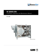
CA3XRT shown
CA2XRT
CA3XRT
CA4XRT
CA SERIES ERV
Installation, Operation and Maintenance Manual

1.800.627.44992
CA-Series Rooftop
ERV
RISK OF FIRE, ELECTRIC SHOCK, OR INJURY.
OBSERVE ALL CODES AND THE FOLLOWING:
1. Before serviceing or cleaning the unit, switch power off at
system disconnect switch or service panel and lock-out/
tag-out to prevent power from being switched on acciden-
tally. More than one disconnect switch may be required to
de-energize the system for servicing.
2. This installation manual shows the suggested installation
method. Additional measures may be required by local
codes and standards.
3. Installation work and electrical wiring must be done by
qualified professional(s) in accordance with all applicable
codes, standards, and licensing requirements.
4. Any structural alterations necessary for installation must
comply with all applicable building, health, and safety code
requirements.
5. Electrical equipment connected to this unit must be properly
grounded.
6. Sufficient air is needed for proper combustion and exhaust-
ing of gases through the flue (chimney) of fuel burning
equipment that might be installed in the area affected by
this equipment. If this unit is exhausting air from a space in
which chimney-vented fuel burning equipment is located,
take steps to assure that combustion air supply require-
ments of applicable codes and standards.
7. Use the unit only in the manner intended by the manufac-
turer. If you have questions, contact the manufacturer.
8. This unit is intended for general ventilating only. Do not use
to exhaust hazardous or explosive materials and vapors. Do
not connect this unit to range hoods, fume hoods, or collec-
tion systems for toxics.
9. This unit must be properly ducted to the outdoors. Outside
air inlets must not be located where air may be contami-
nated, for example by vehicle or appliance exhausts.
WARNING
Maximum Differential Pressure
The maximum pressure differential between the two air-
streams shound not exceed 4 inches (H2O).
CAUTION
The unit’s outside air inlet should be at least 10' away from any
exhaust, such as dryer vents, chimneys, furnace, and water
heater exhausts, or other sources of contamination or carbon
monoxide. Do not locate the outside air intet where vehicles
may be serviced or left idling. Never locate the unit inside a
structure.
WARNING
Danger of damage or severe injury if high winds move this unit.
Secure unit to structure. Observe local code requirements at a
minimum.
WARNING
It is the installer’s responsibility to make sure that the screws
or bolts used for securing the units are properly selected for
the loads and substrates involved. Secure the CA2–4XRT so
that it cannot fall or tip in the event of an accident, structural
failure, or earthquake. See the Rigging Information section for
unit weight.
RenewAire strongly recommends that you secure rooftop
units properly to the building structure. Strong winds,
tornados, and hurricanes can and do displace or remove
rooftop equipment from rails or curbs. When this happens,
the equipment, adjacent roof structure, and even vehicles
parked near the building can be damaged, and rain typically
enters the building. The equipment is put out of service and
the collateral damage can be very expensive.
CAUTION
Provide Adequate Service Access for Maintenance
The CA-Series Rooftop cabinet will require regular filter and
core inspections. Install the CA-Series Rooftop cabinet where
you can remove the doors for cleaning the core and replaceing
the filters, and where you can get at the wiring for installation
and service.
CAUTION
Tape both inner and outer vapor barriers of insulated duct to
collars on duct adapters. This is critical to prevent migration
of moisture into insulation. Build-up of moisture can result in
failure of the duct system and/or frost in the insulation. Make
sure any tears in the inner and outer vapor barriers are sealed.
CAUTION
Danger of injury if unit started unexpectedly. Switch power off
at service disconnect. Lock-out/tag-out the disconnect.
WARNING
Filters must be used or the energy exchanger core will become
blocked by dust and the unit will not do its job. In extreme
cases components may be damaged.
CAUTION
Do Not Wash the Energy Exchange Core.
Keep it away from water or fire to avoid damaging it. Always
handle the core carefully.
CAUTION

31.800.627.4499
CA-Series Rooftop ERV
SAVE THIS MANUAL
UNIT INFORMATION
Record information as shown below.
In the unlikely event that factory assistance is ever required, information located on the unit
label will be needed.
Locate the RenewAire unit label found on the outside of the unit.
NOTE: This information is for purposes of identifying the unit-specific option data from the
Option Code.
SO#: 063585
JO#: 35920-0000
Option Code: CA-4XJRT--S-------------N
This space left blank intentionally.
Serial Number:
MODEL/MODELE:
Energy Recovery Ventilator
Label No:
134784_002
CA4XRT
J19 4987
UNIT INFORMATION
UNIT LABEL (TYPICAL)
C - -X -- -R - -A -J - -- -T - -
OPTION CODE:
SERIAL NUMBER:
SO #:
OWNER INFORMATION
NOTE: This page
is to be completed
by the installing
contractor. The completed
document is to be turned
over to the owner after
start-up.
N

1.800.627.44994
RENEWAIRE.COM 1.800.627.4499
8
SPECIFICATIONS & DIMENSIONS
Specifi cations may be subject to change without notice.
ROOFTOP UNITS
Modular Cabinets
Description CA2XRT CA3XRT CA4XRT
Typical Airfl ow
Range CFM 500-2,200 750-3,300 1,000-4,400
AHRI 1060 Certifi ed Core Two L125-G5 Three L125-G5 Four L125-G5
Unit Dimensions
& Weight
55 1/2" L x 43 1/4" W x
42 1/4" H
250-329 lbs.
55 1/2" L x 63 1/2" W x
42 1/2" H
377-482 lbs.
55 1/2" L x 83 1/4" W x
42 1/4" H
462-593 lbs.
Max. Shipping Dimensions
& Weight (on pallet)
63" L x 47" W x 48" H
400 lbs.
60" L x 90" W x 48" H
590 lbs.
60" L x 90" W x 48" H
700 lbs.
Filters: MERV 8:
20" x 20" x 2" Total qty. 4 Total qty. 6 Total qty. 8
ThermalPerformanceRatingsG52015.2.xlsx 2Cores(IOM)
30%
50%
70%
90%
500 1000 1500 2000
Effectiveness(%)
Airflow(CFM)
CA2XRT
ThermalPerformanceRatingsG52015.2.xlsx 3Cores(IOM)
30%
50%
70%
90%
500 1000 1500 2000 2500 3000 3500
Effectiveness(%)
Airflow(CFM)
CA3XRT
ThermalPerformanceRatingsG52015.2.xlsx 4Cores(IOM)
30%
50%
70%
90%
1000 2000 3000 4000
Effectiveness(%)
Airflow(CFM)
CA4XRT
CA‐RTFlowRatingsAnalysis.xlsx Chart
0.0
0.5
1.0
1.5
2.0
0 1000 2000 3000 4000
Static Presure
Drop (in.w.g)
Airflow (CFM)
CA‐RTFlowRatingsAnalysis.xlsx Chart
0.0
0.5
1.0
1.5
2.0
0 1000 2000 3000 4000
Static Presure
Drop (in.w.g)
Airflow (CFM)
CORE PERFORMANCE AIRFLOW PERFORMANCE
At AHRI 1060 standard conditions.
See all AHRI certifi ed ratings at www.ahrinet.org.
Note: Airfl ow performance includes effect of clean,
standard fi lter supplied with unit.
SPECIFICATIONS
Ventilation Type:
Static plate, heat and humidity transfer
Standard Features:
Insulated sheet metal cabinets with energy
exchange cores and fi lters.
Blower not included and must be specifi ed to
meet job requirements.
Insulation:
One inch, high density, FSK faced, fi berglass
Options:
Double wall construction
Exterior paint - white, custom colors
Accessories:
Roof curb - standard 14"
Filters - MERV 13, 2" (shipped loose)
OUTDOORCA Energy Recovery Module
Download specification at:
renewaire.com/specifications
CA-SERIES
35 1/2" Case
55 1/2" Overall
33 7/8" Minimum
Service Area
35 1/2" Minimum
Service Area
C
L
9 1/2"
C
L
25 7/8"
C
L
20 1/4"
Typ.
TOP VIEW
Alternate Hood Location.
If hood location switched,
plug existing mounting holes
on opposite side of unit to
prevent leakage.
24" X 10"
Floor Opening
Typ.
Door
Swing
26 1/4" I.D.
12 5/8" I.D.
28 7/8" I.D.
33 7/8" I.D.
37 5/8" O.D.
32 5/8" O.D.
5 3/4"
1 7/8"
AA
FA
RA
CURB CA2XRT
4"
Typ.
8 1/8"
Typ.
37 5/8"
Lifting Lugs
41 3/4" Case
43 1/4" Overall
2"
Typ.
Floor pan inlets/outlets are open by
default; These can be patched from
inside the unit with removeable insulated
pans from the side openings, if unused.
LEFT VIEW
35 3/4"
Lifting Lugs
Note: Pleated, disposable 20" X 20" X
2" filters are provided for installation
and are interchangeable based on
your airflow path requirements. Filters
are to be mounted upstream to the
core in the direction of airflow
entering the unit.
FRONT VIEW
OA Hood can be
mounted to either
side of unit
Pressure Ports
(4) Typ.
24 1/8"
Typ.
25 1/4"
Typ.
10"
Typ.
39 1/8" Case
42 1/4" Overall
Lower side pan inlets/outlets
are patched with
removable insulated pans.
RIGHT VIEW
1 7/8"
14"
3"
SECTION A-A
CURB CROSS-SECTION A-A (TYP.)
1 1/2" X 1/4"
Neoprene Gasket
3/4" X 3 1/2"
Wooden Nailer
TOP VIEW
Model: CA2XRT
Drawing Type: Unit Dimension
Version: MAY16
ABBREVIATIONS
EA: Exhaust Air to outside
OA: Outside Air intake
RA: Room Air to be exhausted
FA: Fresh Air to inside
INSTALLATION ORIENTATION
Unit must be installed in orientation
shown.
NOTE
1. UNLESS OTHERWISE SPECIFIED,
DIMENSIONS ARE ROUNDED TO THE
NEAREST EIGHTH OF AN INCH.
2. SPECIFICATIONS MAY BE SUBJECT
TO CHANGE WITHOUT NOTICE.
CA2XRT Energy Recovery Module
AIRFLOW CONFIGURATION
Available as shown in dimension drawing.
UNIT MOUNTING & APPLICATION
Must be mounted as shown. Duct confi guration is
fi eld convertible. Weather hood can be moved in
the fi eld. RA/EA airstream can be switched with
OA/FA airstream.

51.800.627.4499
FOR THE MOST COMPLETE AND CURRENT INFORMATION VISIT RENEWAIRE.COM 9
SPECIFICATIONS & DIMENSIONS
Specifi cations may be subject to change without notice.
ROOFTOP UNITS
Modular Cabinets
Description CA2XRT CA3XRT CA4XRT
Typical Airfl ow
Range CFM 500-2,200 750-3,300 1,000-4,400
AHRI 1060 Certifi ed Core Two L125-G5 Three L125-G5 Four L125-G5
Unit Dimensions
& Weight
55 1/2" L x 43 1/4" W x
42 1/4" H
250-329 lbs.
55 1/2" L x 63 1/2" W x
42 1/2" H
377-482 lbs.
55 1/2" L x 83 1/4" W x
42 1/4" H
462-593 lbs.
Max. Shipping Dimensions
& Weight (on pallet)
63" L x 47" W x 48" H
400 lbs.
60" L x 90" W x 48" H
590 lbs.
60" L x 90" W x 48" H
700 lbs.
Filters: MERV 8:
20" x 20" x 2" Total qty. 4 Total qty. 6 Total qty. 8
ThermalPerformanceRatingsG52015.2.xlsx 2Cores(IOM)
30%
50%
70%
90%
500 1000 1500 2000
Effectiveness(%)
Airflow(CFM)
CA2XRT
ThermalPerformanceRatingsG52015.2.xlsx 3Cores(IOM)
30%
50%
70%
90%
500 1000 1500 2000 2500 3000 3500
Effectiveness(%)
Airflow(CFM)
CA3XRT
ThermalPerformanceRatingsG52015.2.xlsx 4Cores(IOM)
30%
50%
70%
90%
1000 2000 3000 4000
Effectiveness(%)
Airflow(CFM)
CA4XRT
CA‐RTFlowRatingsAnalysis.xlsx Chart
0.0
0.5
1.0
1.5
2.0
0 1000 2000 3000 4000
Static Presure
Drop (in.w.g)
Airflow (CFM)
CA‐RTFlowRatingsAnalysis.xlsx Chart
0.0
0.5
1.0
1.5
2.0
0 1000 2000 3000 4000
Static Presure
Drop (in.w.g)
Airflow (CFM)
CORE PERFORMANCE AIRFLOW PERFORMANCE
At AHRI 1060 standard conditions.
See all AHRI certifi ed ratings at www.ahrinet.org.
Note: Airfl ow performance includes effect of clean,
standard fi lter supplied with unit.
SPECIFICATIONS
Ventilation Type:
Static plate, heat and humidity transfer
Standard Features:
Insulated sheet metal cabinets with energy
exchange cores and fi lters.
Blower not included and must be specifi ed to
meet job requirements.
Insulation:
One inch, high density, FSK faced, fi berglass
Options:
Double wall construction
Exterior paint - white, custom colors
Accessories:
Roof curb - standard 14"
Filters - MERV 13, 2" (shipped loose)
OUTDOORCA Energy Recovery Module
Download specification at:
renewaire.com/specifications
CA-SERIES
35 1/2" Case
55 1/2" Overall
33 7/8" Minimum
Service Area
35 1/2" Minimum
Service Area
C
L
9 1/2"
C
L
25 7/8"
C
L
20 1/4"
Typ.
TOP VIEW
Alternate Hood Location.
If hood location switched,
plug existing mounting holes
on opposite side of unit to
prevent leakage.
24" X 10"
Floor Opening
Typ.
Door
Swing
26 1/4" I.D.
12 5/8" I.D.
28 7/8" I.D.
33 7/8" I.D.
37 5/8" O.D.
32 5/8" O.D.
5 3/4"
1 7/8"
AA
FA
RA
CURB CA2XRT
4"
Typ.
8 1/8"
Typ.
37 5/8"
Lifting Lugs
41 3/4" Case
43 1/4" Overall
2"
Typ.
Floor pan inlets/outlets are open by
default; These can be patched from
inside the unit with removeable insulated
pans from the side openings, if unused.
LEFT VIEW
35 3/4"
Lifting Lugs
Note: Pleated, disposable 20" X 20" X
2" filters are provided for installation
and are interchangeable based on
your airflow path requirements. Filters
are to be mounted upstream to the
core in the direction of airflow
entering the unit.
FRONT VIEW
OA Hood can be
mounted to either
side of unit
Pressure Ports
(4) Typ.
24 1/8"
Typ.
25 1/4"
Typ.
10"
Typ.
39 1/8" Case
42 1/4" Overall
Lower side pan inlets/outlets
are patched with
removable insulated pans.
RIGHT VIEW
1 7/8"
14"
3"
SECTION A-A
CURB CROSS-SECTION A-A (TYP.)
1 1/2" X 1/4"
Neoprene Gasket
3/4" X 3 1/2"
Wooden Nailer
TOP VIEW
Model: CA2XRT
Drawing Type: Unit Dimension
Version: MAY16
ABBREVIATIONS
EA: Exhaust Air to outside
OA: Outside Air intake
RA: Room Air to be exhausted
FA: Fresh Air to inside
INSTALLATION ORIENTATION
Unit must be installed in orientation
shown.
NOTE
1. UNLESS OTHERWISE SPECIFIED,
DIMENSIONS ARE ROUNDED TO THE
NEAREST EIGHTH OF AN INCH.
2. SPECIFICATIONS MAY BE SUBJECT
TO CHANGE WITHOUT NOTICE.
CA2XRT Energy Recovery Module
AIRFLOW CONFIGURATION
Available as shown in dimension drawing.
UNIT MOUNTING & APPLICATION
Must be mounted as shown. Duct confi guration is
fi eld convertible. Weather hood can be moved in
the fi eld. RA/EA airstream can be switched with
OA/FA airstream.

1.800.627.44996
RENEWAIRE.COM 1.800.627.4499
10
SPECIFICATIONS & DIMENSIONS
35 1/2" Case
55 1/2" Overall
33 3/4" Minimum
Service Area
35 1/2" Minimum
Service Area
C
L
9 1/2"
C
L
26"
C
L
30 1/4"
Typ.
TOP VIEW
Alternate Hood Location. If hood location
switched, plug existing mounting holes on
opposite side of unit to prevent leakage.
36" X 10"
Floor
Opening
Typ.
Door
Swing
38 1/4" I.D.
12 3/8"
I.D.
28 7/8" I.D.
53 3/4" I.D.
57 1/2" O.D.
32 5/8"
O.D.
9 5/8"
1 7/8"
A
A
FA
RA
TOP VIEW
5"
Typ.
12"
Typ.
57 5/8" Lifting Lugs
61 1/2" Case
63 3/8" Overall
2"
Typ.
Floor pan inlets/outlets are open by
default; These can be patched from
inside the unit with removeable insulated
pans from the side openings, if unused.
LEFT VIEW
35 3/4"
Lifting Lugs
Note: Pleated, disposable 20" X 20" X 2"
filters are provided for installation and
are interchangeable based on your
airflow path requirements. Filters are
to be mounted upstream to the core
in the direction of airflow entering the
unit.
FRONT VIEW
OA Hood can be
mounted to either
side of unit
Pressure Ports
(4) Typ.
36 1/8" Typ.
10" Typ.
24 7/8" Typ.
39 1/4" Case
42 1/4" Overall
Lower side pan inlets/outlets
are patched with
removable insulated pans.
RIGHT VIEW
3"
1 7/8"
14"
SECTION A-A
1 1/2" X 1/4"
Neoprene Gasket
3/4" X 3 1/2"
Wooden Nailer
CURB CROSS-SECTION A-A (TYP.)
CURB CA3XRT
Model: CA3XRT
Drawing Type: Unit Dimension
Version: MAY16
ABBREVIATIONS
EA: Exhaust Air to outside
OA: Outside Air intake
RA: Room Air to be exhausted
FA: Fresh Air to inside
INSTALLATION ORIENTATION
Unit must be installed in orientation
shown.
NOTE
1. UNLESS OTHERWISE SPECIFIED,
DIMENSIONS ARE ROUNDED TO THE
NEAREST EIGHTH OF AN INCH.
2. SPECIFICATIONS MAY BE SUBJECT
TO CHANGE WITHOUT NOTICE.
CA3XRT Energy Recovery Module
AIRFLOW CONFIGURATION
Available as shown in dimension drawing.
UNIT MOUNTING & APPLICATION
Must be mounted as shown. Duct confi guration is
fi eld convertible. Weather hood can be moved in
the fi eld. RA/EA airstream can be switched with
OA/FA airstream.
CA-SERIES
35 1/2" Case
C
L
9 1/2"
C
L
26"
33 7/8" Minimum
Service Area
35 1/2" Minimum
Service Area
C
L
40 1/8"
Typ.
TOP VIEW
Alternate Hood Location. If hood location
switched, plug existing mounting holes on
opposite side of unit to prevent leakage.
48" X 10"
Floor Openings
Typ.
Door
Swing
50 1/2" I.D.
12 5/8"
I.D.
28 7/8" I.D.
73 3/8" I.D.
77 1/8" O.D.
32 5/8" O.D.
13 3/8"
1 7/8"
A
A
FA
RA
TOP VIEW
5 7/8"
Typ.
16"
Typ.
77 1/4" Lifting Lugs
81 3/8" Case
83" Overall
2"
Typ.
Floor pan inlets/outlets are open by
default; These can be patched from
inside the unit with removeable insulated
pans from the side openings, if unused.
LEFT VIEW
30 5/8"
Lifting Lugs
55 1/2" Overall
Note: Pleated, disposable
20" X 20" X 2" filters are
provided for installation and
are interchangeable based
on your airflow path
requirements. Filters are to
be mounted upstream to
the core in the direction of
airflow entering the unit.
FRONT VIEW
OA Hood can be
mounted to either
side of unit
Pressure Ports
(4) Typ.
48 1/8" Typ.
10" Typ.
24 7/8" Typ.
39 1/4" Case
42 1/8" Overall
Lower side pan inlets/outlets
are patched with
removable insulated pans.
RIGHT VIEW
1 7/8"
3"
14"
SECTION A-A
1 1/2" X 1/4"
Neoprene Gasket
3/4" X 3 1/2"
Wooden Nailer
CURB CROSS-SECTION A-A (TYP.)
CURB CA4XRT
Model: CA4XRT
Drawing Type: Unit Dimension
Version: MAY16
ABBREVIATIONS
EA: Exhaust Air to outside
OA: Outside Air intake
RA: Room Air to be exhausted
FA: Fresh Air to inside
INSTALLATION ORIENTATION
Unit must be installed in orientation
shown.
NOTE
1. UNLESS OTHERWISE SPECIFIED,
DIMENSIONS ARE ROUNDED TO THE
NEAREST EIGHTH OF AN INCH.
2. SPECIFICATIONS MAY BE SUBJECT
TO CHANGE WITHOUT NOTICE.
CA4XRT Energy Recovery Module
AIRFLOW CONFIGURATION
Available as shown in dimension drawing.
UNIT MOUNTING & APPLICATION
Must be mounted as shown. Duct confi guration is
fi eld convertible. Weather hood can be moved in
the fi eld. RA/EA airstream can be switched with
OA/FA airstream.

71.800.627.4499
FOR THE MOST COMPLETE AND CURRENT INFORMATION VISIT RENEWAIRE.COM 11
SPECIFICATIONS & DIMENSIONS
35 1/2" Case
55 1/2" Overall
33 3/4" Minimum
Service Area
35 1/2" Minimum
Service Area
C
L
9 1/2"
C
L
26"
C
L
30 1/4"
Typ.
TOP VIEW
Alternate Hood Location. If hood location
switched, plug existing mounting holes on
opposite side of unit to prevent leakage.
36" X 10"
Floor
Opening
Typ.
Door
Swing
38 1/4" I.D.
12 3/8"
I.D.
28 7/8" I.D.
53 3/4" I.D.
57 1/2" O.D.
32 5/8"
O.D.
9 5/8"
1 7/8"
A
A
FA
RA
TOP VIEW
5"
Typ.
12"
Typ.
57 5/8" Lifting Lugs
61 1/2" Case
63 3/8" Overall
2"
Typ.
Floor pan inlets/outlets are open by
default; These can be patched from
inside the unit with removeable insulated
pans from the side openings, if unused.
LEFT VIEW
35 3/4"
Lifting Lugs
Note: Pleated, disposable 20" X 20" X 2"
filters are provided for installation and
are interchangeable based on your
airflow path requirements. Filters are
to be mounted upstream to the core
in the direction of airflow entering the
unit.
FRONT VIEW
OA Hood can be
mounted to either
side of unit
Pressure Ports
(4) Typ.
36 1/8" Typ.
10" Typ.
24 7/8" Typ.
39 1/4" Case
42 1/4" Overall
Lower side pan inlets/outlets
are patched with
removable insulated pans.
RIGHT VIEW
3"
1 7/8"
14"
SECTION A-A
1 1/2" X 1/4"
Neoprene Gasket
3/4" X 3 1/2"
Wooden Nailer
CURB CROSS-SECTION A-A (TYP.)
CURB CA3XRT
Model: CA3XRT
Drawing Type: Unit Dimension
Version: MAY16
ABBREVIATIONS
EA: Exhaust Air to outside
OA: Outside Air intake
RA: Room Air to be exhausted
FA: Fresh Air to inside
INSTALLATION ORIENTATION
Unit must be installed in orientation
shown.
NOTE
1. UNLESS OTHERWISE SPECIFIED,
DIMENSIONS ARE ROUNDED TO THE
NEAREST EIGHTH OF AN INCH.
2. SPECIFICATIONS MAY BE SUBJECT
TO CHANGE WITHOUT NOTICE.
CA3XRT Energy Recovery Module
AIRFLOW CONFIGURATION
Available as shown in dimension drawing.
UNIT MOUNTING & APPLICATION
Must be mounted as shown. Duct confi guration is
fi eld convertible. Weather hood can be moved in
the fi eld. RA/EA airstream can be switched with
OA/FA airstream.
CA-SERIES
35 1/2" Case
C
L
9 1/2"
C
L
26"
33 7/8" Minimum
Service Area
35 1/2" Minimum
Service Area
C
L
40 1/8"
Typ.
TOP VIEW
Alternate Hood Location. If hood location
switched, plug existing mounting holes on
opposite side of unit to prevent leakage.
48" X 10"
Floor Openings
Typ.
Door
Swing
50 1/2" I.D.
12 5/8"
I.D.
28 7/8" I.D.
73 3/8" I.D.
77 1/8" O.D.
32 5/8" O.D.
13 3/8"
1 7/8"
A
A
FA
RA
TOP VIEW
5 7/8"
Typ.
16"
Typ.
77 1/4" Lifting Lugs
81 3/8" Case
83" Overall
2"
Typ.
Floor pan inlets/outlets are open by
default; These can be patched from
inside the unit with removeable insulated
pans from the side openings, if unused.
LEFT VIEW
30 5/8"
Lifting Lugs
55 1/2" Overall
Note: Pleated, disposable
20" X 20" X 2" filters are
provided for installation and
are interchangeable based
on your airflow path
requirements. Filters are to
be mounted upstream to
the core in the direction of
airflow entering the unit.
FRONT VIEW
OA Hood can be
mounted to either
side of unit
Pressure Ports
(4) Typ.
48 1/8" Typ.
10" Typ.
24 7/8" Typ.
39 1/4" Case
42 1/8" Overall
Lower side pan inlets/outlets
are patched with
removable insulated pans.
RIGHT VIEW
1 7/8"
3"
14"
SECTION A-A
1 1/2" X 1/4"
Neoprene Gasket
3/4" X 3 1/2"
Wooden Nailer
CURB CROSS-SECTION A-A (TYP.)
CURB CA4XRT
Model: CA4XRT
Drawing Type: Unit Dimension
Version: MAY16
ABBREVIATIONS
EA: Exhaust Air to outside
OA: Outside Air intake
RA: Room Air to be exhausted
FA: Fresh Air to inside
INSTALLATION ORIENTATION
Unit must be installed in orientation
shown.
NOTE
1. UNLESS OTHERWISE SPECIFIED,
DIMENSIONS ARE ROUNDED TO THE
NEAREST EIGHTH OF AN INCH.
2. SPECIFICATIONS MAY BE SUBJECT
TO CHANGE WITHOUT NOTICE.
CA4XRT Energy Recovery Module
AIRFLOW CONFIGURATION
Available as shown in dimension drawing.
UNIT MOUNTING & APPLICATION
Must be mounted as shown. Duct confi guration is
fi eld convertible. Weather hood can be moved in
the fi eld. RA/EA airstream can be switched with
OA/FA airstream.

1.800.627.44998
CA-Series Rooftop
ERV
1.0 OVERVIEW 9
1.1 CA-SERIES OPERATION .......................................... 9
1.2 APPLICATION GUILDLINES ....................................... 9
1.2.1 Purpose of CA-Series Rooftop Cabinets ...............................9
1.2.2 General Layout ...................................................................9
1.3 SERVICE ACCESS ..................................................10
1.3.1 Service Access .................................................................10
1.3.2 Connection to HVAC System .............................................. 10
2.0 INSTALLATION 10
2.1 BLOWER ORIENTATION .........................................10
2.1.1 Pull-Pull—Recomended .................................................... 11
2.1.2 Advantages ....................................................................... 11
2.1.3 Disadvantages .................................................................. 11
2.2 BLOWER SIZING ...................................................11
2.3 STATIC PRESSURE DROP THROUGH THE CABINET .11
2.4 PLACEMENT OF THE CA-SERIES ROOFTOP ............12
2.5 RIGGING INFORMATION .........................................12
2.6 MOUNTING THE CA-SERIES ROOFTOP ...................13
2.6.1 On Roof Curbs .................................................................. 13
2.6.2 On Equipment Rails........................................................... 13
2.7 DUCTING ..............................................................13
2.8 INSIDE DUCTWORK SYSTEM .................................14
TABLE OF CONTENTS
TABLE OF ILLUSTRATIONS
Figure 1.3.0 CA-Series Rooftop Cross Section ............................................................................................................................................9
Figure 2.1.0 CA-Series Rooftop Blower Orientation ................................................................................................................................... 10
Figure 2.3.0 Rated Pressure Drop Through Cabinet .................................................................................................................................. 11
Figure 2.5.0 CA-Series Rooftop Unit and Corner Weights (lbs) .................................................................................................................. 12
Figure 2.7.0 CA-Series Rooftop Ducting Information ................................................................................................................................. 13
Figure 2.8.0 CA-Series Rooftop Ducting Configuration 1 ........................................................................................................................... 14
Figure 2.8.1 CA-Series Rooftop Ducting Configuration 2 ........................................................................................................................... 15
Figure 2.8.2 CA-Series Rooftop Ducting Configuration 3 ........................................................................................................................... 15
Figure 3.6.0 Proper Operating Airflow Range ............................................................................................................................................ 16
Figure 3.6.1 Pressure Tap Locations ........................................................................................................................................................ 17
Figure 3.6.2 Differential Static Across Core DSP vs. CFM ......................................................................................................................... 17
Figure 4.4.0 CA-2XRT Initial Pressure Drop 20" x 20" MERV 8 Filters ....................................................................................................... 18
Figure 4.4.1 CA-3XRT Initial Pressure Drop 20" x 20" MERV 8 Filters ....................................................................................................... 19
Figure 4.4.2 CA-4XRT Initial Pressure Drop 20" x 20" MERV 8 Filters ....................................................................................................... 19
3.0 OPERATION 15
3.1 PRINCIPAL OF OPERATION ....................................15
3.2 CHECKING THAT UNIT IS OPERATING ..................... 15
3.2.1 Airflow ............................................................................. 15
3.2.2 Use Static Taps in Doors to Measure Airflow Rates ............ 15
3.3 ENERGY EXCHANGE .............................................. 16
3.4 CONTINUOUS OPERATION .....................................16
3.5 OPERATION IN EXTREME COLD WEATHER .............16
3.6 MEASURE AIRFLOW .............................................. 16
3.6.1 Equipment Required .......................................................... 16
3.6.2 Cross Core Static Pressure Measurement Instructions ....... 16
4.0 MAINTENANCE 17
4.1 CHANGING THE FILTERS .......................................17
4.2 GENERAL CLEANING AND INSPECTION ..................17
4.3 CLEAN THE ENERGY EXCHANGE CORE ..................17
4.4 FILTERS ...............................................................18
4.4.1 Filter Specifications ..........................................................18
4.4.2 Filter Resistance ............................................................... 18
5.0 FACTORY ASSISTANCE ...........................19

91.800.627.4499
CA-Series Rooftop ERV
1.0 OVERVIEW
1.1 CA-SERIES ROOFTOP OPERATION
The CA-Series Rooftop cabinets have one basic purpose: to transfer heating or cooling energy
from an exhaust airstream to a fresh airstream.
The CA-Series Rooftop cabinets operate with no moving parts. The cores in the modules will
transfer energy between the two airstreams as long as the two system blowers are moving air
through the module. (These blowers are separate from the cabinets).
1.2 APPLICATION GUIDELINES
1.2.1 Purpose of CA-Series Rooftop
The CA-Series Rooftop cabinets are modular cases with 2, 3, or 4 energy recovery cores.
A variety of duct connection configurations are possible. Disposable filters are provided; they
are of a common size and can easily be replaced.
1.2.2 General Layout
The CA-Series Rooftop cabinets are used to transfer energy from exhaust air leaving a building,
into fresh air being brought in from the outside for ventilation. By recoverying energy from the
exhaust airstream, the benefits of ventilation can be enjoyed without the full energy cost to
condition the outside air.
The CA-Series Rooftop cabinets do not contain blowers. Therefore, two blowers must be
installed as part of the system. Several ducts must also be installed.
CONFIGURATION CODE
MODEL NUMBER
Model
1 2 3 4 5 6 7 8 9 10 11 12 13 14 15 16 17 18 19 20 21 22 23 24 25
J - -
DIGIT NUMBER
Digits 1 - 5:
*NOTES:
Digit 6 "J" = G5 Core Type Digits 9-10 and 12-23 are not used in these models.
Other Options
Digit 24:
"-" = None
"W" = White Paint
"C" = Custom Paint
"X" = Custom Unit
Safety Listing
Digit 25:
"N" = Non-Listed
"CA-2X" = Cabinet Applied 2 Cores
"CA-3X" = Cabinet Applied 3 Cores
"CA-4X" = Cabinet Applied 4 Cores
---- ------ N
Wall Type
Digit 11:
"S" = Single
"D" = Double
CA RT- --
CA ROOFTOP
APPLIED PRODUCT CONFIGURATION CODE

1.800.627.449910
CA-Series Rooftop
ERV
The maximum pressure
differential between the
two airstreams shound not
exceed 4 inches (H2O).
CAUTION
2.0 INSTALLATION
2.1 BLOWER ORIENTATION
Two blowers will be required: one for the air to be exhausted from the building, another for the
fresh air to be brought into the building. See diagram for proper and improper blower locations.
FIGURE 2.1.0 CA-SERIES ROOFTOP BLOWER ORIENTATION
INSTALLATION
Alternate
Construction
1.3 SERVICE ACCESS
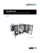
1.3.1 Service Access
Install the ERV where you can open the door for cleaning the core and filter. Although there is
no electrical connection to the cabinet, there should be a nearby system disconnect switch, so
service people can shut off the blowers connect to the system when changing filters.
1.3.2 Connection to the HVAC System
In most cases, one or two ducts connect the CA-Series Rooftop cabinet to the building’s ducted
HVAC system. A variety of connection approaches are possible, depending on the number of CA-
Series Rooftop cabinets in the installation, purpose of the system, and available space.
The filters must cover the INLET FACES of the cores. Filter racks are provided at each face to
handle all possible airflow configurations.
FIGURE 1.3.0 CA-SERIES ROOFTOP CROSS SECTION

111.800.627.4499
CA-Series Rooftop ERV
INSTALLATION
2.3 STATIC PRESSURE DROP THROUGH THE CABINET
The following chart is to be used when considering a Pull-Pull orientation of the blowers. The
chart represents clean filters. It will be necessary to add an additional drop to allow for the
build-up of dirt on the filters.
FIGURE 2.3.0 RATED PRESSURE DROP THROUGH CABINET
CA‐RTFlowRatingsAnalysisMAR16 Chart
0.0
0.5
1.0
1.5
2.0
0 1000 2000 3000 4000
Static Presure
Drop (in.w.g)
Airflow (CFM)
2.2 BLOWER SIZING
Most “low airflow” problems in the field are caused by under-sized blowers. Systems can
under-perform if the designer does not make sufficient allowance for duct leakage, variations in
duct layout from ideal design, less-than-ideal blower outlet conditions, dirty filters, and the like.
In general, ventilation systems with energy-recovery components tend to need blowers with
relatively high static pressure curves. In addition, parts of the duct system may be operating
at higher static pressures than usual, and greater duct leakage may result. While these
effects may be small, they may consume a large portion of the “safety factor” that a designer
conventionally adds in every blower selection exercise.
Given all these concerns, it is prudent to select blowers and motors that can be operated at
higher RPMs than required by the nominal design.
2.1.1 Pull-Pull—RECOMMENDED
This is the recommended blower orientations for virtually every application. In “Pull-Pull”
applications, both pull from the cabinet.
With Pull-Pull blower orientation, there is generally no need to review the static pressure
differences between the two airstreams.
An “RA Push-FA Pull” blower orientation is unacceptable.
The advantage is that both blowers are on the “outside” of the cabinets, taking advatage of
the acoustic attenuation offered by the cabinets. If outside airstream bypass airflow occurs, it
additionally insures no exhaust contaminants leak past seals into the fresh air.
The disadvantage is that both blowers must be sized to provide the additional bypass air, which
in most cases is a needless waist of energy.
The higher overall static pressure tend to increase duct leakage.
NOTE: This bypass
air volume is
lower than in most
competing technologies,
such as heat wheels, and
even some other plate-type
exchangers.

1.800.627.449912
CA-Series Rooftop
ERV
Provide Adequate Service Access for Maintenance
The CA-Series Rooftop cabinet will require regular filter and core inspections. Install the CA-
Series Rooftop cabinet where you can remove the doors for cleaning the core and replacing the
filters, and where you can get at the wiring for installation and service.
CAUTION
The CA-Series Rooftop cabinet is available from the factory in one configuration where room air
enters the bottom of the unit and fresh air exits the bottom of the unit. The relocatable patch
pans allow different duct connection configurations.
2.5 RIGGING INFORMATION
There are lifting lugs at each upper corner of the unit. Use slings or shackles at all four corners.
Spreader bars are recommended in order to avoid damage to the unit.
INSTALLATION
It is the installer’s responsibility to make sure that the screws or bolts used for securing the units
are properly selected for the loads and substrates involved. Secure the CA-Series Rooftop cabi-
net so that it cannot fall or tip in the event of an accident, structural failure, or earthquake. See
Rigging Information for unit weight.
RenewAire strongly recommends that you secure rooftop units properly to the building struc-
ture. Strong winds, tornados, and hurricanes can and do displace or remove rooftop equip-
ment from rails or curbs. When this happens, the equipment, adjacent roof structure, and
even vehicles parked near the building can be damaged, and rain typically enters the build-
ing. The equipment is put out of service and the collateral damage can be very expensive.
CAUTION
The unit’s outside air inlet should be at least 10' away from any exhaust, such as dryer vents,
chimneys, furnace, and water heater exhausts, or other sources of contamination or carbon
monoxide. Do not locate the outside air inlet where vehicles may be serviced or left idling. Never
locate the unit inside a structure.
WARNING
Danger of damage or severe injury if high winds move this unit. Secure unit to structure. Ovserve
local code requirements at a minimum.
WARNING
2.4 PLACEMENT OF THE CA-SERIES ROOFTOP
The CA-Series Rooftop cabinet is designed for installation on a roof or other outside location.
Select a location that is central to the inside duct runs, and close to any other air handler that
might be part of the system.

131.800.627.4499
CA-Series Rooftop ERV
2.6.2 On Equipment Rails:
Review drawing of Roof Curb and specify Equipment Rail to fit.
Before installing CA-Series Rooftop cabinets, apply roofing and counterflashing to Equipment
Rails as per standard practice.
Set CA-Series Rooftop cabinet in place. We recommend bolting through sides of unit base into
the Equipment Rails to secure the unit against high winds.
2.7 DUCTING
Before unit is installed on Curb:
Basic Requirements:
Always connect an RA and an FA duct to each Rooftop unit.
The RA and FA ducts can be interchanged depending on where you install the OA hood.
With standard configuration units, both ducts are inside the building. In other unit, that
utilize the optional configuration openings, at least one of the ducts is outside and must be
weatherized.
Any weatherized duct must be thermally insulated to prevent condensation on the inside or
outside of the duct. The duct lining must be vapor-sealed, and the duct exterior must be rain
tight.
Duct(s) connected to the bottom of the CA-Series Rooftop cabinet are generally installed at this
time. Install (2) ducts with CA-Series Rooftop cabinet standard configuration.
Drop duct(s) into openings in top of roof curb.
Install appropriate gasket on top of Roof Curb and edges of ducts.
NOTE: OA Hood
provided, can be
mounted on either
side of the cabinet
over the upper cabinet
openings. See Duct Con-
nection locations below
depending on which side of
the cabinet the OA hood is
installed.
INSTALLATION
2.6 MOUNTING THE CA-SERIES ROOFTOP
2.6.1 On Roof Curbs:
The base of the CA-Series Rooftop cabinets are designed for installation on our optional Roof
Curb. See Curb portion on Dimension Drawings.
Before installing CA-Series Rooftop cabinets, apply roofing and counterflashing to Roof Curb as
per standard practice.
Install appropriate gasket on top of Roof Curb.
Set CA-Series Rooftop cabinet in place. We recommend bolting through sides of unit base into
the Roof Curb to secure the unit against high winds.
12/3/12 WD
SPECIFICATIONS SUBJECT
TO CHANGE WITHOUT NOTICE.
RenewAire LLC
Scale: 1" = 24"
Do not scale drawing
CA-RT_CORNER_WEIGHTS_DEC12.dwg
CA-RT Corner Weights
822 3/4
A
LR RR
LF RF
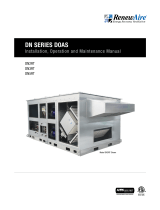
CA2-4XRT CABINET UNIT WEIGHTS (LBS)
MODELS UNIT Dim "A" LF LR RR RF
CA2XRT 250 39 3/8
"
71 69 54 56
CA3XRT 377 59 1/4" 107 104 81 85
CA4XRT 462 79" 131 128 99 104
TOP VIEW
(CA2XRT depicted)
FIGURE 2.5.0 CA-SERIES ROOFTOP UNIT AND CORNER WEIGHTS (LBS) (CA2XRT DEPICTED)
12/3/12 WD
SPECIFICATIONS SUBJECT
TO CHANGE WITHOUT NOTICE.
RenewAire LLC
Scale: 1" = 24"
Do not scale drawing
CA-RT_CORNER_WEIGHTS_DEC12.dwg
CA-RT Corner Weights
822 3/4
A
LR RR
LF RF
CA2-4XRT CABINET UNIT WEIGHTS (LBS)
MODELS UNIT Dim "A" LF LR RR RF
CA2XRT 250 39 3/8
"
71 69 54 56
CA3XRT 377 59 1/4" 107 104 81 85
CA4XRT 462 79" 131 128 99 104
TOP VIEW
(CA2XRT depicted)

1.800.627.449914
CA-Series Rooftop
ERV
2.8 INSIDE DUCTWORK SYSTEM
Follow Engineer’s Ductwork Design:
u Ductwork should be designed by an engineer to allow the unit to provide the required airflow.
u Ducts should enter and exit the unit through smoot gradual transitions.
u If the inside ducts run through un-conditioned spaces, they must be insulated, with a sealed
vapor barrier on both inside and outside of insulation.
See drawings below for examples of some common installation approaches.
INSTALLATION
FIGURE 2.8.0 CA-SERIES ROOFTOP DUCTING CONFIGURATION 1
Tape both inner and outer vapr barriers of insulated duct to collars on duct adapters. This is criti-
cal to prevent migration of moisture into insulation. Build-up of moisture can result in failure of
the duct system and/or frost in the insulation. Make sure any tears in the inner and outer vapor
barriers are sealed.
CAUTION
FIGURE 2.7.0 CA-SERIES ROOFTOP DUCTING INFORMATION
RA
FA
IF HOOD IS
HERE
RA
FA
IF HOOD IS
HERE
19 3/4"
CLEARANCE
FOR HOOD
19 3/4"
CLEARANCE
FOR HOOD
35 1/4"
SERVICE AREA
FOR DOOR
BOTTOM VIEW

151.800.627.4499
CA-Series Rooftop ERV
OPERATION
3.0 OPERATION
3.1 PRINCIPAL OF OPERATION
The CA-Series Rooftop cabinet has one basic purpose: to exhaust air from a structure and bring
in fresh air from outside, while transferring heating or cooling energy from the exhaust air to the
fresh air.
The CA-Series Rooftop cabinet is a very simple device, and will accomplish this purpose as long
as the blowers for both airstreams are able to move air through the energy-exchange core.
3.2 CHECKING THAT UNIT IS OPERATING
3.2.1 Airflow
Airflow should be occurring in both airstreams. Sometimes the easiest place to confirm that air
is moving is at the weatherhoods.
If exact airflow is critical, it may be desirable to permanently install flow measuring stations and
manometers in the ductwork connected to the unit. These also can be used to determine when
filters should be cleaned or changed.
3.2.2 Use Static Taps in Doors to Measure Airflow Rates
See “Cross-Core Static Drop” in MEASURING AIRFLOW table. These may be used to directly
measure airflow in the unit.
FIGURE 2.8.2 CA-SERIES ROOFTOP DUCTING CONFIGURATION 3
FIGURE 2.8.1 CA-SERIES ROOFTOP DUCTING CONFIGURATION 2

1.800.627.449916
CA-Series Rooftop
ERV
Model CFM
CA2X 500–2200
CA3X 750–3300
CA4X 1000–4400
3.6 MEASURING AIRFLOW
3.6.1 Equipment Required
u A magnehelic gauge or other device capable of measuring 0–1.5 inch water of differential
pressure.
u Two pieces of natural rubber latex tubing, 1/8" ID, 1/16" wall works the best.
3.6.2 Cross Core Static Pressure Measurement Instructions
u The individual differential static pressures (DSP) can be measured using the installed
pressure ports located in the front of the units core access doors.
u To read SCFM of Fresh Air (FA), install the “high” pressure side (+) of your measuring device
to the Outside Air (OA) port and the “low” pressure side (-) to the FA port.
u To read SCFM of Room Air (RA) install the “high” pressure side (+) of your measuring device
to the RA port and the “low” pressure side (-) to the Exhaust Air (EA) port.
u Use the reading displayed on your measurement device to cross reference the CFM output
using the conversion chart.
NOTE: Be sure to
remove cap from
pressure port
before inserting tubing.
Insure tubing is well seated
in pressure port.
NOTE: The tubing
should extend in
thepressure port
approximately 1".
NOTE: These
ports have been
carefully located
on the unit as to give you
the most accurate airflow
measurement.
NOTE: Do not
relocate pressure
ports.
NOTE: Be sure to
replace cap into
pressure port
when air flow measuring is
completed.
FIGURE 3.6.0 PROPER OPERATING AIRFLOW RANGE
OPERATION
3.3 ENERGY EXCHANGE
Precise determination of installed sensible energy exchange effectiveness requires careful
measurement of temperatures and air flows in all four airstreams, and in practice is somewhat
difficult.
It is possible to confirm that energy is being exchanged simply by feeling the ducts. If the
Fresh Air duct from the unit into the room is closer to room temperature than to the outside
temperature, energy is being recovered.
3.4 CONTINUOUS OPERATION
Continuous operation is acceptable in virtually all conditions. Unit will not be damaged by
continuous operation as long as air flow occurs. Blower motors may overheat if filters become
completely blocked due to lack of maintenance. With continuous operation, some external
frosting may occur in very cold weather (see below).
3.5 OPERATION IN EXTREME COLD WEATHER
Unit is capable of operating at outside temperatures down to -10˚F, with indoor humidities below
40%, without any internal frosting. Unit can operate at more severe conditions occasionally
with little or no impact on its performance. At lower humidities, it can operate at lower outside
temperatures without freezing the energy-exchange core.

171.800.627.4499
CA-Series Rooftop ERV
MAINTENANCE
4.0 MAINTENANCE
4.1 CHANGING THE FILTERS
Inspect and/or replace filters every 2–3 months when the unit is in regular use, or as needed.
u Turn off unit completely! Lock-out and tag-out the system disconnect switch.
u Open the door. The door is secured with turn-type latches.
u Remove and dispose of all filters. Replace all filters.
u Close the door.
4.2 GENERAL CLEANING AND INSPECTION
Perform general cleaning and inspection when changing filters.
u Remove paper, leaves, etc. from inlet and outlet screens.
u Inspect for insect nests.
4.3 CLEAN THE ENERGY EXCHANGE CORE
Clean the core annually.
u Remove the filters.
u Vacuum the exposed faces of the energy exchanger core with a soft brush.
u Vacuum out dust from the rest of the unit case.
u Install new filters.
NOTE: See chart
for information
on the initial
resistance of the filters
originally supplied with this
unit. If replacement filters
have higher resistance, the
airflow of the system will
be lower.
DSP 0.20" 0.25" 0.30" 0.35" 0.40" 0.45" 0.50" 0.55" 0.60" 0.65" 0.70" 0.75"
CA2X
Fresh Air (FA)
CFM
529 662 794 926 1058 1191 1323 1455 1588 1720 1852 1985
Room Air (EA) 567 709 851 993 1134 1276 1418 1560 1701 1843 1985 2127
CA3X
Fresh Air (FA) 818 1023 1227 1432 1636 1841 2045 2250 2454 2659 2863 3068
Room Air (EA) 732 915 1098 1281 1464 1647 1830 2013 2196 2379 2562 2745
CA4X
Fresh Air (FA) 1221 1526 1832 2137 2442 2747 3053 3358 3663 3969 4274 4579
Room Air (EA) 1130 1412 1695 1977 2260 2542 2825 3107 3390 3672 3955 4237
FIGURE 3.6.2 DIFFERENTIAL STATIC ACROSS CORE DSP VS. CFM
FIGURE 3.6.1 PRESSURE PORT LOCATIONS
PRESSURE
PORTS (4) TYP.

1.800.627.449918
CA-Series Rooftop
ERV
4.4 FILTERS
4.4.1 Filter Specifications
u 20" x 20" x 2" (nominal) pleated filters
u Actual size: 19.5" x 19.5" x 1.75"
Units are shipped with MERV 8 Filters. Minimum recommended effectiveness is MERV 6.
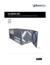
4.4.2 Filter Resistance
Initial resistance of filters supplied with this unit:
FIGURE 4.4.0 CA-2XRT INITIAL PRESSURE DROP 20" X 20" MERV 8 FILTERS
MAINTENANCE
Pleated_Filter_PD_APR16 (2)20x20x2 MERV 8 (IOM)
0.0
0.1
0.2
0.3
0.4
500 1000 1500 2000
Clean-filter Pressure Drop (in.w.g.)
Unit Airflow (CFM)
Initial Pressure Drop of MERV 8 Filters
supplied with this unit
Filters must be used or the energy exchanger core will become blocked by dust and the unit will
not do its job. In extreme cases components may be damaged.
CAUTION
Do Not Wash the Energy Exchange Core.
Keep it away from water or fire to avoid damaging it. Always handle the core carefully.
CAUTION
ALWAYS DISCONNECT POWER SOURCE BEFORE SERVICING, TO ENSURE NO AIR FLOW IN THE
SYSTEM.
High volume of air in the case when operating! If you open an access door when the system
is running, you may be exposed to as much as 8,000 CFM! Severe eye injury could result!
WARNING
IMPORTANT
Make sure all four lips of the core enter the receiver channels when re-inserting the core into
the unit.

191.800.627.4499
CA-Series Rooftop ERV
FACTORY ASSISTANCE
FIGURE 4.4.2 CA-4XRT INITIAL PRESSURE DROP 20" X 20" MERV 8 FILTERS
In the unlikely event that you need assistance from the factory for a specific issue, make sure
that you have the information called for in the Unit Records page in the Owner Information
section of this manual. The person you speak with at the factory will need that information to
properly identify the unit and the installed options.
To contact RenewAire Customer Service:
Call 800-627-4499
Email: RenewAireSuppor[email protected]
Remember that RenewAire Customer Service can only assist with the products sold by
RenewAire, it cannot resolve engineering issues that result from air handling system design by
others.
5.0 FACTORY ASSISTANCE
FIGURE 4.4.1 CA-3XRT INITIAL PRESSURE DROP 20" X 20" MERV 8 FILTERS
Pleated_Filter_PD_APR16 (4)20x20x2 MERV 8 (IOM)
0.0
0.1
0.2
0.3
0.4
500 1000 1500 2000 2500 3000 3500 4000
Clean-filter Pressure Drop (in.w.g.)
Unit Airflow (CFM)
Initial Pressure Drop of MERV 8 Filters
supplied with this unit
Pleated_Filter_PD_APR16 (3)20x20x2 MERV 8 (IOM)
0.0
0.1
0.2
0.3
0.4
500 1000 1500 2000 2500 3000 3500
Clean-filter Pressure Drop (in.w.g.)
Unit Airflow (CFM)
Initial Pressure Drop of MERV 8 Filters
supplied with this unit

About RenewAire
For over 30 years, RenewAire has been a pioneer in enhancing indoor air quality (IAQ)
in commercial and residential buildings of every size.This is achieved while maximizing
sustainability through our fifth-generation, static-plate, enthalpic-core Energy Recovery
Ventilators (ERVs) that optimize energy efficiency, lower capital costs via load reduction and
decrease operational expenses by minimizing equipment needs, resulting in significant energy
savings. Our ERVs are competitively priced, simple to install, easy to use and maintain and have
a quick payback. They also enjoy the industry’s best warranty with the lowest claims due to
long-term reliability derived from innovative design practices, expert workmanship and Quick
Response Manufacturing (QRM).
As the pioneer of static-plate core technology in North America, RenewAire is the largest ERV
producer in the USA. We’re committed to sustainable manufacturing and lessening our
environmental footprint, and to that end our Waunakee, WI plant is 100% powered by wind
turbines. The facility is also one of the few buildings worldwide to be LEED and Green Globes
certified, as well as having achieved ENERGY STAR Building status. In 2010, RenewAire joined
the Soler & Palau (S&P) Ventilation Group in order to provide direct access to the latest in energy-
efficient air-moving technologies. For more information, visit: renewaire.com
Member of the S&P Group
Family of Brands
2021 © RenewAire LLC
148051_003_JUN21
201 Raemisch Road | Waunakee, WI | 53597 | 800.627.4499 | RenewAire.com
/