Page is loading ...

INTRODUCTION
Congratulations on your Portable Plasma Cutter purchase. You have purchased one of
the most reliable, technologically advanced and economical portable plasma cutters
available today. This machine will allow you to cut almost any material that conducts
electricity including mild steel, galvanized steel, stainless steel, and aluminum to name
a few.
This owner’s manual has been designed to instruct you on a safe operation and
maintenance of your Plasma Cutting System. If you read and follow the instructions in
this manual, your Plasma Cutter will provide you with years of trouble free operation.
If you do not read and understand this owner’s manual, you MAY significantly shorten
the operating life and may also operate the unit under unsafe conditions, which may
result in SERIOUS INJURY OR DEATH!
If you have any questions regarding the information contained in this manual, contact
your local distributor or the factory help line @ 800-554-0074.
SAFETY
Follow Safety Instructions – Read carefully all safety messages in this manual and
safety labels on the machine. Do not let anyone operate the machine without complete
understanding of the safety instructions.
Electric Shock Can Kill – Personal contact with live electrical parts can cause fatal
shock or severe burns. The torch uses high voltage (>250VDC) and produces an
electrical arc in excess of 10,000°F. Never touch the torch body, workpiece, ground
clamp or the cutting table water when the cutter is in operation as a shock could result.
Electric Shock Prevention
- Wear insulated gloves and boots.
- Insulate operator from work and ground with mats or covers.
- Always operate machine in a dry environment.
- Use fixtures or clamps to secure workpiece in place.
- Provide earth ground to work, fixtures, tables and water tray.
- Inspect all electrical cables for damage, wear or exposed copper.
- Never bypass or short-cut machine ground.
- Disconnect power cord before checking, replacing components or servicing
machine.

SAFETY
(cont.)
Plasma Arc Can Burn Operator – The arc will cut through protective gloves, boots and
clothing as well as human skin and bone.
- Keep away from the torch tip and arc.
- Do not hold metal near the cutting arc.
- Never point the torch towards yourself or others.
Plasma Arc Ray Can Damage Eyes – Plasma Arc rays produce intense visible and
invisible (ultraviolet & infrared) rays that can cause eye damage. Protective eyewear
should always be worn when operating the plasma cutter.
- Wear safety glasses, goggles or welding helmet with proper lens shading.
- Install UV blocking safety screens around work area.
- Install warning signs instructing people not to watch the arc.
Recommended Lens Shade
Arc Current <100 Amps #8 (AWS) #11 (ISO 4850)
Arc Noise Can Damage Hearing – Prolonged exposure to noise can damage hearing.
Appropriate hearing protection should be worn during operation.
Cutting Can Cause Fire or Explosion – The plasma cutter generates an arc with
intense heat to cut through material. This heat can ignite flammable materials, including
gases, on contact leading to fire or explosion.
Fire & Explosion Prevention
- Keep a fire extinguisher (correctly shielded) close to the work area.
- Remove all flammable material within 35 feet of work area.
- Provide adequate ventilation of explosive dusts and gases.
- Never cut pressurized cylinders, pipes or any closed container.
- Never cut containers or tanks that have held combustible materials
- Do not use oxygen or other flammable gases as cutting plasma gas.
SETUP & OPERATION

Initial Machine Inspection – Inspect the machine, torch and all components included
in the shipping carton.
Contact your retailer or distributor and report any missing items. Have your machine
model and serial number ready for any claim.
Contact your freight carrier immediately if unit was damaged in shipment and file a
claim. All damage claims are the responsibility of the carrier that damaged the unit and
any copies of bills of lading or other required materials, will be furnished by your retailer
or distributor.
Contents of Carton – Your plasma cutting system includes the following items:
1) Plasma cutting machine with the following attachments:
a) Plasma cutting torch with 13 foot cable assembly.
b) Heavy-duty work clamp with cable assembly
c) Power cord with 3-prong UL plug.
d) ¼” NPT air line connector
2) Spare cutting tips (bag containing 5 pieces)
3) Spare Electrodes (bag containing 3 pieces)
4) Operators manual
Machine Setup – Before beginning any cutting operations it is important to set the
machine up correctly. The machine will not function properly without careful attention to
the line power supply, compressed air supply, work grounding clamp and torch contact.
Electrical Power Supply – The machine supply voltage is clearly labeled on the back
of the machine near the power cord. Note the following required NEMA outlets and
corresponding minimum supply Amps for operation.
Line Power Requirements
Voltage Amp (min) Cycles (Hz) Outlet
120 Volt 20A 60Hz 5-15R
240 Volt 15A 60Hz 6-15R
NOTE: Insufficient line voltage or amperage can cause the torch not to fire.

Compressed Air Supply
– The machine requires clean & dry air with adequate head-
pressure and flow-rates of for optimal operation. The air for cutting can be supplied by
a shop compressor or air cylinder with a high-pressure regulator. It is recommended
that an external air filter & dryer unit be attached directly to the machine air inlet.
Clean - The torch has internal air ports that are smaller in diameter than a human
hair. If these ports become blocked, reduced cutting capacity and overheating
can occur.
Dry – The plasma arc is generated with a high voltage charge of electricity
ionizing the compressed air. Any water in the air will result in arc grounding,
which reduces cutting power. Additionally, the extreme temperature of the arc will
cause the water to instantaneously turn to steam that can damage the torch.
Pressure – A minimum air pressure of 72 PSI (5.0 bar) is required. Pressures in
excess of 120-PSI (9.4 bar) can damage the machine.
Flow – A minimum flow rate of 4.5 scfm (127 l/min) is required for cool
operation of the cutting torch. Insufficient flow rates will reduce cutting depths,
reduce consumable life and can result in complete torch failure.
NOTE: If the supply-line is disconnected from the machine or the air pressure
drops below 30 PSI, the low-air limit switch will engage
and the torch will not fire.
Air Hose Mounting – The supply line air hose that is attached the plasma cutter should
be of sufficient size and construction to insure safe operation.
Fitting – A factory supplied ¼” NPT male air inlet fitting is located on the back of
the machine. When attaching the filter/dryer, quick dis-connect coupler or air
hose fitting be sure to use liquid pipe sealant only.
Hose – An air hose with a minimum inside diameter of 3/8” (9.5mm) should be
used on the machine to insure adequate airflow.
NOTE: Never use Teflon tape on this fitting as small pieces of the tape can break
off and block the flow of air to the machine.
Work Clamp Mounting – The work clamp must be attached to the workpiece while
cutting and should be as close to the cut area as possible. Make sure that the surface
under the clamp is free of contamination or paint that could interfere with the electrical
connection. Do not attach the clamp to the piece of material that is being cut.

Operating the Plasma Cutter
– Now that all of the necessary setup connections and
work area conditions have been made, you are ready to start cutting with your new
plasma machine.
Power ON – With the torch cable completely uncoiled and making sure the
trigger is not depressed, turn the power switch to the “ON” position. At this
time you see the toggle switch light go on and will hear the internal cooling fan
energize.
Air ON – Check to see that the machine is receiving supply air by reading the air
pressure gauge on the front panel. The air regulator is factory set for optimal
performance between 45-60 PSI and initial adjustment should not be necessary.
Torch READY – The torch should be held 1/16” off the edge, or directly in
contact with the surface for a piercing cut, of the workpiece.
Trigger ON – Depress the trigger and the torch will fire. Move the torch to the
workpiece, setting the tip directly on the surface as you move through the
material. This insures a clean, smooth cut with minimal back spatter.
Cutting Torch Operation – The Nu-Tec torch provides the latest in plasma cutting
torch technology with a compact ergonomic design for ease of operation.
The torch is designed for contact cutting on both the 25 & 35 units.
Cutting – Hold the torch so the flat end of the cutting tip is parallel to the cutting
surface and just off the edge. Start the torch against edge of the workpiece and
move it into the material making light contact as you cut. If sparks fly up at the
operator, you are moving the torch too fast.
Piercing – When a pierce (start) hole is required, hold the torch straight down to
the surface and hold it fixed in place until the flash sparks stop and the sparks
shoot through the material. Then move across the surface in a standard cutting
mode.
Work Clamp – Always make sure the work clamp is attached to the cutting
surface. The work clamp completes the electrical circuit during high amperage
cutting, which reduces the load on the torch cable.
WARNING
Firing the torch more than 1/8” from the cutting surface greatly reduces
consumable life and may cause permanent torch damage.

MAINTENA
NCE & REPAIR
Installing / Replacing Torch Consumables – Now that you have completed some
cuts and noticed reduced cutting speed, reduced cutting depth, or a ragged edge, it is
time to replace the torch consumables.
WARNING
The power switch should be in the “OFF” position and the line cord should be
disconnected from the outlet while replacing torch consumables.
Benchtop – The torch should be resting on a bench surface with the tip facing up
during disassembly and re-assembly. The work area should be clean of all debris as
the torch components contain very small air ports that are easily contaminated. Items
that drop from the torch should be cleaned and inspected before re-installing.
Shield Cup – Loosen the shield cup by turning counter-clockwise from the cutting tip
end. Inspect for debris, surface burn-through and/or damage to the inner bore towards
the top of the cup. If the cup is severely burned and/or any cooling air ports are
blocked, replace the cup.
Cutting Tip – Lift the cutting tip off the torch body and inspect for wear. If the center
hole diameter is larger than 1/16” and/or not round, replace the tip.
Swirl Ring – The swirl ring (gas diffuser) is mounted at the base of the cutting tip and
channels the cutting gas across the electrode. Inspect for cracks or plugged air holes
and replace as required.
Electrode – The electrode may be removed by simply putting a wrench or pliers on the
flats and turning loose like a screw. Inspect for wear and pitting. If the work end is
pitted (concave) or burned away by 1/16” as compared to a new electrode, replace with
new electrode.
Torch Head – While the torch is disassembled, it is a good idea to inspect the complete
torch head for signs of clogged air ports or damaged o-rings. The torch head should not
require replacement except in the event of contamination (water, oil or dirt in the air
supply) or overheating due to poor maintenance. If the torch head is deformed due to
excessive heat, dis-assemble handle and replace
Re-assembly – Take care to return components to their original position, especially the
swirl ring, and “snug” shield cup into place. Do not over-tighten shield cup as damage
to the internal torch tip components may result.

Troubleshooting Guide
Problem
Procedure
1.
Power "ON" light not illuminated
Power cord not plugged into outlet - Plug-in cord
Outlet not energized - Check circuit breaker/dis-connect
Low Voltage - Check for proper line voltage at outlet
2.
Cooling fan not running
Power switch in "OFF" position - Switch power "ON"
Finger guard blocking fan blade - Bend away from blade
3.
No or low air pressure on gauge
Air line not attached to machine - Attach air line
Air supply line shut-off - Turn air supply "ON"
Regulator set too low- Pull knob and adjust
Filter/dryer devices installed incorrectly - Repair
4.
Torch does not fire - no air flow through torch
Power is switched "OFF" or not connected - See #1
Air pressure is off or too low to ignite torch - See #3
Shield Cup not correctly installed - See Consumables
5.
Torch does not fire - air flow through torch
Low supply voltage- Check outlet voltage
Air pressure too high - Adjust to 65 psi
Torch missing or failed components - Check torch
Worn /damaged cutting tip - Replace
Worn/damaged electrode - Replace
6.
The arc will not stay "lit"
Air pressure is set too high - Reduce pressure setting
Inconsistent air flow - Check for contamination & filter
Worn or damaged consumables - Replace consumables
Low or varying voltage - New service or add transformer
- Remove extension cord
7.
The arc "Sputters" and flares
Check for water in air line - Add air dryer
Check for contamination in air line - Add air filter
8.
The arc does not transfer to the workpiece
Work Clamp failure - Check clamp location & connection
Torch is too far from workpiece - Move torch within 1/8"
Technical Questions – In the event additional assistance is required beyond the scope
of this trouble-shooting guide or custom plasma products are desired, please contact
your local distributor or the factory direct line at 800-554-0074.

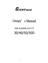
NPT40 Plasma Torch Consumables
1) Torch Head 70° 907N9602 2) Standard Electrode 907N0110
3) Swirl Ring/Gas Diffuser (20-50A) 907N0106 4) Cutting Tip (30A) 907N1168
5) Shield Cup 907N1160 6) Stand-Off (40Amp only) 907N0010
Specifications – Power Supply
Rated Power Supply
Single Phase / 60 Hz
Rated Input Current (I1) & Voltage (U1)
20A @ 120 Volts / 16A @ 208 / 14A @ 240 Volts
Rated Output Current (I2)
18A @ 120 Volts / 25A @ 208 / 28A @ 240 Volts
Rated Open Circuit Voltage (Uo)
290 VDC
Rated Output Voltage (U2)
94 VDC
Duty-Cycle @ 40°C
60%
Air/Gas Pressure (Min.)
60 PSI (4.2 bar)
Air/Gas Flow Rate (Min.)
4.5 scfm (127 l/min.)
Weight (Shipping Carton)
46 Lbs.

NPT40 Plasma Cutting Torch
– Parts List
Operator Manual 25/35, Rev 3. (May 2006)
/