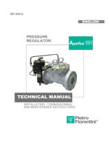
Elster J125B Regulator 1 1/2'', 2'' Operating instructions
- Type
- Operating instructions

Commissioning Instructions
General Arrangements
Parts Lists
Maintenance Instructions
For: J125B MKII Regulator with balanced valve
1 ½”, 2” & 50mm size
Service Regulator
Inlet pressures up to 8.6bar
Nominal Diameter ¾” – 2”
HONEYWELL
ELSTER JEAVONS
J125B

2
OPERATING INSTRUCTIONS
• Ensure that this product is suitable for the chosen application.
• Installation, adjustment and maintenance by authorised, trained
personnel only.
• When being fitted to an appliance, refer to the appliance
manufacturers instructions.
FITTING REGULATOR INTO PIPEWORK
1. The unit should not be installed in a corrosive environment.
2. The ambient temperature (surface temperature) should be within
the limits stated on the regulator catalogue.
3. Check the maximum allowable pressure on the regulator nameplate
against the installation specification.
4. Remove the protection plugs from inlet and outlet ports.
5. Ensure that installation pipework is thoroughly clean.
6. The direction of gas flow must be the same as arrows on regulator
body. See Fig. 1.
7. Install the regulator into pipework using jointing compound
approved to national standards.
8. In order to fit the regulator into confined spaces it may be necessary
to rotate the diaphragm case. This is achieved by slacking off the
three set screws, rotating the diaphragm case, and then re-
tightening the set screws evenly. See Fig. 2.
9. For units with no OPSS fitted it is advised that a slam shut device is
fitted to protect downstream equipment.
INSTALLATION OF VENT LINE.
1. Remove clip and vent screen from regulator top cover.
2. Connect the vent line (2"), using a jointing compound approved to
national standards, and lead to atmosphere in accordance with
national standards. Ensure that no water can penetrate vent
pipeline. See Fig. 3.
3. If the regulator is fitted with an internal relief valve, ensure that the
vent line is of sufficient diameter to carry gas vented by the relief
valve to a safe outside location. Reference to any national standard.
INSTALLATION OF IMPULSE LINE
4. Remove the plastic protection plug.
5. Connect the impulse line (½"), using a jointing compound approved
to national standards, and lead to a point downstream not less than
fifteen times the nominal pipe diameter from the outlet. See Fig. 4.
FOR PRE-SET UNITS ONLY.
1. Turn off downstream valves.
2. Slowly turn on inlet supply.
3. If safety shut-off device is not fitted, go to instruction 6.
Fig. 1
Fig. 2
Fig. 3
Fig. 1
Fig. 2
Fig. 3
Fig. 4
Warning! Incorrect installation, adjustment, modification, operation and
maintenance may cause injury or damage.
Read the instructions before use. This control must be installed in accordance with the
rules in force.
J125B: Commissioning Instructions

3
4. If safety shut-off device is fitted unscrew reset spindle end cap and
firmly pull. Hold in this position until the outlet pipework is fully
pressurized, then release reset spindle end cap gently. See Fig. 5.
5. Re-screw reset spindle end cap into body, ensuring not to jam reset
spindle.
6. Commission downstream appliances.
WARNING: DO NOT UNDER ANY CIRCUMSTANCES WEDGE
OPEN SAFETY SHUT-OFF RESET END CAP AS THIS WILL
NOT ALLOW THE SAFETY DEVICE(S) TO FUNCTION IN
ADVERSE PRESSURE CONDITIONS.
SETTING THE REGULATOR & SAFETY
SHUT OFF DEVICE PRESSURES.
OPSS = Over Pressure Safety Shut-off.
UPSS = Under Pressure Safety Shut-off.
1. Turn off inlet and outlet valves.
2. Remove top cap from regulator cover.
3. Insert an 1¼" A/F socket over the top of the adjustment screw.
4. Turn anticlockwise (-) to reduce loading on regulator spring to
minimum. See Fig. 6 (If no safety devices fitted go to instruction 10).
5. Remove top cap from safety shut-off device cover (If UPSS only go to
instruction 8).
6. Insert a flat bladed screwdriver into one of the partial slots on the
OPSS spring holder. See Fig. 7.
7. Turn clockwise (+) to increase loading on OPSS spring to maximum.
8. If UPSS fitted, insert a pozidriv screwdriver (No.2 point) into UPSS
adjusting screw in bottom spring holder. See Fig. 8.
9. Turn anticlockwise (-) to reduce loading on UPSS spring, making
sure screw head does not protrude from the bottom spring holder.
10. Slowly open inlet valve(s).
11. If safety device fitted, re-cock by unscrewing reset spindle end cap
and pulling firmly. Hold in this position until the outlet pipework is
fully pressurised, then release reset spindle end cap gently. Re-screw
reset spindle end cap into body. See Fig. 5.
12. Turn regulator adjustment screw clockwise (+) to increase the
loading on the spring until the required outlet pressure, plus
approximately 2.5mbar (1"wg) is obtained. (This is an allowance for
the regulator being set with zero flowrate).
If UPSS only go to instruction 20, if no safety device go to instruction 27.
13. Block vent valve opening to prevent relief valve from operating.
14. Apply external pressure source to a suitable point on the outlet
pipework. Increase pressure to that required for OPSS trip-off.
Note: If pressure test point on underside of slam shut unit is used as
external source point, care must be taken to ensure pressures are
equalised across restricted orifice within test point.
15. Slowly turn OPSS spring holder anticlockwise (-) until OPSS device
trips off. See Fig. 7.
16. Reduce external pressure source to level set in instruction 12.
Fig. 5
Fig. 6
Fig. 7
J125B: Commissioning Instructions

4
17. Re-cock OPSS device by unscrewing reset spindle end cap and
firmly pull. Hold in this position until the outlet pipework is fully
pressurized, then release reset spindle end cap gently. Re-screw
reset spindle end cap into body. See Fig. 9.
18. Slowly increase external pressure to check for OPSS trip-off. Trim
adjustment if necessary and repeat instructions 16 - 18.
19. Remove external pressure source.
NOTE: OPSS device is now set.
20. Close inlet valves.
21. Reduce inlet pressure to approximately 140mbar (2 PSI).
22. Reduce outlet pressure by introducing a slow controlled bleed until
the required UPSS trip-off pressure is obtained and close bleed.
23. Slowly turn UPSS adjusting screw clockwise (+) until UPSS device
trips off. See Fig. 8.
24. Slowly open inlet valve to regain inlet pressure up to approximately
140mbar (2 PSI), then close inlet valve.
25. Re-cock UPSS device by unscrewing reset spindle end cap and
firmly pull. Hold in this position until the outlet pipework is fully
pressurised, then release reset spindle end cap gently. Re-screw
reset spindle end cap into body. See Fig. 9.
26. Slowly reduce outlet pressure to check for UPSS trip-off. Trim
adjustment if necessary and repeat instructions 24 – 26.
NOTE: UPSS device is now set.
27. Commission installations.
28. Trim the regulator outlet pressure if necessary, once normal flow
rates have been achieved.
29. Unblock vent opening.
30. Replace all top caps (seal if necessary).
WARNING: DO NOT UNDER ANY CIRCUMSTANCES WEDGE
OPEN SAFETY SHUT-OFF RESET END CAP AS THIS WILL NOT
ALLOW THE SAFETY DEVICE(S) TO FUNCTION IN ADVERSE
PRESSURE CONDITIONS.
Fig. 8
Fig. 9
J125B: Commissioning Instructions

5
Fig. 10
Fig. 11
Fig. 12
IF THE REQUIRED REGULATOR OUTLET PRESSURE
CANNOT BE ACHIEVED WITH THE SPRING FITTED
31. Remove top cap from regulator cover.
32. Choose a loading spring from catalogue or page 17 that will give the
required outlet pressure range.
33. Fully unscrew and remove the spring holder, See Fig. 11.
34. Remove spring and replace with new one. See Fig. 10.
35. Screw spring holder back in place, ensuring regulator spring is
located in recess in underside of holder.
36. Adjust the outlet pressure as described previously.
37. Replace the top cap (seal if necessary).
NOTE: Outlet pressure is now set
IF THE REQUIRED TRIP-OFF PRESSURES CANNOT BE
ACHIEVED WITH THE SPRINGS FITTED
A) OPSS spring
38. Remove top cap from the safety shut-off device cover.
39. Choose an OPSS spring from the catalogue or page 17 that will give
the required pressure range.
40. Fully unscrew and remove top spring holder. See Fig. 11.
41. Remove spring and replace with new one. See Fig. 9.
42. Screw spring holder back in place, ensuring that castellated spigot is
uppermost in chimney. See Fig. 11.
43. Adjust the trip-off pressure as described previously.
44. Replace the top cap (seal if necessary).
NOTE: OPSS pressure is now set
B) UPSS spring.
45. Remove top cap from the safety shut-off device cover.
46. Choose an UPSS spring from the catalogue or page 17 that will give
the required pressure range.
47. Fully unscrew and remove top spring holder. See Fig. 12.
48. Remove OPSS spring (or spacer tube if UPSS only).
J125B: Commissioning Instructions

6
49. Remove bottom spring holder and UPSS top spring holder.
50. Remove UPSS spring and replace with new one. See Fig. 12.
51. Replace UPSS spring holder, ensuring that spigot locates in UPSS
spring.
52. Replace bottom spring holder locating three webs into slots in
bottom of cover, ensuring not to disturb UPSS spring and UPSS
spring holder.
53. Replace OPSS spring (or spacer tube if UPSS only).
54. Screw top spring holder back in place, ensuring that castellated
spigot is uppermost in chimney. See Fig. 11. (If UPSS only ensure
that spacer tube is firmly clamped)
55. Adjust the trip-off pressure as described previously
56. Replace the top cap (seal if necessary).
NOTE: UPSS pressure is now set.
Fig. 12
J125B: Commissioning Instructions

7
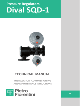
S1 VERSION
(NO RELIEF VALVE)
S3 VERSION
(LIMITED RELIEF VALVE)
DIAPHRAGM CASE
ASSEMBLY
SEE FIG. 17
S2 VERSION
(FULL CAPACITY RELIEF VALVE)
41
38
39
40
42
44
46
16
94
43
J125B: General Arrangement
S1, S2, S3 Assembly – Fig 14

8
DIAPHRAGM CASE
ASSEMBLY
SEE FIG. 17
S4 VERSION
(FULL CAPACITY RELIEF VALVE)
41
38
39
40
44
46
16
94
S10 VERSION
(NO RELIEF VALVE)
S5 VERSION
(LIMITED RELIEF VALVE)
OPSS
SAFETY
SHUT OFF
ASSEMBLY
SEE FIG. 18
J125B: General Arrangement
S4, S5, S10 Assembly- Fig 15

9
DIAPHRAGM CASE
ASSEMBLY
SEE FIG. 17
S8 VERSION
(FULL CAPACITY RELIEF VALVE)
41
38
39
40
44
46
16
94
S11 & S12 VERSION
(NO RELIEF VALVE)
S7 & S9 VERSION
(LIMITED RELIEF VALVE)
OPSS/UPSS
SAFETY
SHUT OFF
ASSEMBLY
SEE FIG. 19
S6, S7 & S11
VERSIONS
UPSS ONLY
SEE FIG. 20
J125B: General Arrangement
S6, S7, S8, S9, S11, S12 Assembly- Fig 16

10
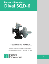
S1, S10, S11 & S12
VERSIONS
(NO RELIEF VALVE)
S3, S5, S7 & S9
VERSIONS
(LIMITED RELIEF VALVE)
33
34
35
36
11
95
35
36
37
S2, S4, S6 & S8
VERSIONS
(FULL RELIEF VALVE)
13
97
10
96
15
12
14
45
7
8
9
95
6
5
4
3
2
1
32
31
30
29
28
27
26
25
24
23
22
21
20
19
18
16
17
J125B: General Arrangement
Diaphragm Case Assembly – Fig 17

11
88
49
89
90
91
TOP COVER TO
BODY FIXING
OPSS BODY TO
ADAPTOR PLATE
FIXING
ENLARGED VIEW
OF VALVE DISC
92
82
81
80
79
65
50
87
86
85
78
84
52
53
54
55
57
58
60
77
72
76
75
74
65
73
72
70
47
61
62
63
64
65
66
67
68
69
71
48
J125B: General Arrangement
OPSS Safety Shut Off Assembly – Fig 18

12
83
82
81
80
79
65
50
87
86
85
78
84
47
61
62
63
64
65
66
67
68
69
71
77
72
76
75
74
65
73
72
70
88
49
89
90
91
TOP COVER TO
BODY FIXING
OPSS BODY TO
ADAPTOR PLATE
FIXING
ENLARGED VIEW
OF VALVE DISC
51
52
53
54
55
56
57
58
59
60
48
J125B: General Arrangement
OPSS/UPSS Safety Shut Off Assembly – Fig 19

13
47
61
62
63
64
65
66
67
68
69
71
77
72
76
75
74
65
73
72
70
88
49
89
90
91
TOP COVER TO
BODY FIXING
OPSS BODY TO
ADAPTOR PLATE
FIXING
ENLARGED VIEW
OF VALVE DISC
51
52
53
54
55
56
93
58
59
60
48
83
82
81
80
79
65
50
87
86
85
78
84
J125B: General Arrangement
UPSS Safety Shut Off Assembly – Fig 20

14
ITEM
DESCRIPTION
PART NUMBER
No. Off
1
TOP CAP
I70103P001
1
2
"O" RING (TOP CAP)
JOBS133
1
3
ADJUSTMENT SCREW
I73183P001
1
4
ROD STOP
I73056P001
1
5
FLANGE STOP ROD
I73174P001
1
6
SPRING ADJUSTING NUT (Full Relief)
I71533P001
1
7
LOADING SPRING
SEE TABLE
1
8
RELIEF VALVE SPRING
I70017P074
1
9
RELIEF VALVE STEM
I73058P001
1
10
"O" RING (BVO PISTON)
JORM0295-30
1
11
FLAT WASHER (No Relief) Not used since 2009
I13981P076
1
12
BVO SENSING SCREW
J12509-118
1
13
BVO PISTON
J12509-117
1
14
BVO PISTON HOLDER
J12509-119
1
15
BVO VALVE SEAT DISC
J12509-121
1
16
SOCKET GRUB SCREW
JSA1012S0NSS
3
17
REGULATOR DIAPHRAGM CASE
J12509-123 (+ if tapped)
1
18
PLUG (C/Sunk Recess ½" BSP Galvanised)
JMFP2G04 (if fitted)
1
PLUG (C/Sunk Recess ½" NPT Galvanised)
I11970P031 (if fitted)
1
19
LEVER ASSEMBLY
I72626P002
1
20
DIAPHRAGM STEM
I72629P005
1
21
HEXAGON NUT
JNA8FZD
12
22
SCREW HEX HEAD
JSA825HHNZG
12
23
DIAPHRAGM (Full Relief)
J12509-116
1
24
DIAPHRAGM PLATE (Full Relief)
I73057P002
1
25
VENT VALVE SEAT
J12509-028
1
26
VENT VALVE DISC
J12509-029
1
27
VENT SCREEN SPRING CLIP
J12509-038
1
28
VENT SCREEN
J12509-037
1
29
VENT VALVE SPRING
J12509-060
1
30
TOP COVER
J12509-079 +
1
31
VENT VALVE GUIDE PIN
J12509-042
1
32
NAMEPLATE
J8112-124
1
33
HEX CAP SCREW
JSNEIHHNZR
1
J125B: Parts List

15
ITEM
DESCRIPTION
PART NUMBER
No. Off
34
SPRING GUIDE
I72272P001
1
35
DIAPHRAGM PLATE (No / Limited Relief)
J12509-126
1
DIAPHRAGM PLATE (No / Limited Relief) before July 2014
I70012P052
1
36
DIAPHRAGM (No / Limited Relief)
J12509-115
1
37
RELIEF VALVE CUP
I73054P002
1
38
SCREWED BODY 1½"
J12508-080 +
1
SCREWED BODY 2"
J12509-080 +
1
FLANGED BODY 50mm
J12509-081 +
1
39
VALVE SEAT (31.8mm)
J12509-108
1
40
IMPULSE TUBE SCREWED
J12509-112
1
IMPULSE TUBE FLANGED
J12509-111
1
41
"O" RING
JORM0195-30
1
42
BLANKING PLATE
J12509-083
1
43
SCREW (Blanking Plate)
JSA616SANSS
4
44
"O" RING
JORM0495-30
1
45
"O" RING
JOBS111
1
46
"O" RING
JOBS338
1
47
ADAPTOR PLATE (USSA)
J12509-082Z02
1
48
SCREW (Adaptor Plate/Regulator Body)
JSA620SANSS
4
49
SCREW (OPSS Body/Adaptor Plate)
JSA516SANSS
4
50
SCREW (Shut-off Diaphragm)
JSA412XPTZ
1
51
UPSS SPRING
SEE TABLE
1
52
SAFETY SHUT OFF SPRING HOLDER
J12506-248
1
53
"O" RING (Safety Shut Off Top Cap)
JORM0251-16
1
54
BOTTOM SPRING HOLDER
J12506-250
1
55
SAFETY SHUT OFF TOP CAP
J12506-142
1
56
SCREW (UPSS Adjustment)
JSA412XPTZ
1
57
OPSS SPRING
SEE TABLE
1
58
SAFETY SHUT-OFF NAMEPLATE
J150D-076
1
59
UPSS SPRING HOLDER
J12506-249
1
60
SAFETY SHUT-OFF TOP COVER
J12506-240 +
1
61
TRIP-OFF LEVER RETAINING PLATE
J12506-243
1
62
TRIP-OFF LEVER
J12506-242
1
63
"O" RING (Impulse Passage)
03110340
1
64
VALVE SPRING
J12506-049
1
J125B: Parts List
Continued

16
ITEM
DESCRIPTION
PART NUMBER
No. Off
65
CIRCLIP VALVE SPINDLE
03627606
4
66
VALVE DISC (Moulded)
J12509-109M
1
67
VALVE SPRING CUP
J12506-251
1
68
"O" RING (Safety Shut off /Adaptor Plate)
JORM0276-24
1
69
CIRCLIP (Front "O" Ring Washer)
JCIR2000K-17B
1
70
SAFETY SHUT OFF BODY
J12506-239 +
1
71
FRONT "O" RING RETAINING WASHER
J12506-252
1
72
"O" RING for Shut-Off Spindle (to end of 2005)
JOBS105D
2
"O" RING for Shut-Off Spindle (from start 2006)
JO4-25
2
73
SAFETY SHUT-OFF VALVE SPINDLE
J12509-110
1
74
PRESSURE TEST NIPPLE
JPTN01-0.71
1
75
TRIP-OFF BUSH
J12506-244
1
76
NEEDLE ROLLER
JNR02S
1
77
STARLOCK WASHER
JCIR1305-043B
1
78
RESET SPINDLE END CAP
J12506-254
1
79
COVER (Spindle End Cap)
J12506-255
1
80
INDICATOR CAP (Safety Shut Off)
JCLOSEMC4
1
81
WASHER-REAR (circlip protection)
J12506-292
1
82
REAR "O" RING RETAINING WASHER
J12506-253
1
83
TRIP-OFF LATCH (OPSS / UPSS and UPSS only)
J12506-241
1
84
LOWER DIAPHRAGM PLATE
J12506-247
1
85
SAFETY SHUT-OFF DIAPHRAGM
J12506-246
1
86
VENT SCREEN
J12506-277
1
87
TOP DIAPHRAGM PLATE
J12506-245
1
88
SCREW (Top Cover/Body)
JSA512TPTS
4
89
"R" CLIP VALVE
33470076
1
90
"O" RING SEAL
03110040
1
91
GASKET VALVE
J12506-267
1
92
TRIP-OFF LATCH (OPSS only)
J12506-322
1
93
UPSS SPACER TUBE
J12506-279
1
94
BONDED SEAL
JBSMB45017
1
95
SPRING LOCATOR ASSEMBLY
I73175G001
1
96
BVO LOADING SPRING
J12509-120
1
97
"O" RING SEAL
JOBS230
1
NOTES: Items marked are contained in spares kits (See table below). Part Numbers ending with + require
connection information.
J125B: Parts List
Continued

17
REGULATOR SPRINGS
mb.
"w.g.
PART NUMBER
COLOUR
8.8 - 15
3.5 - 6
J12509-091
RED
14 - 20
5.5 - 8
J12509-092
ORANGE
21 - 35
8.5 - 14
J12509-093
YELLOW
36 - 70
14.5 - 28
J12509-094
GREEN
69 - 138
1 - 2 PSI
J12509-095
ROYAL BLUE
104 - 173
1.5 - 2.5 PSI
J12509-096
BROWN - ROYAL BLUE
138 - 207
2 - 3 PSI
J12509-097
BROWN - GREEN
207 - 345
3 - 5 PSI
J12506-098
BLACK - GREEN
OVER PRESSURE SLAM-SHUT SPRINGS
mb.
"w.g.
PART NUMBER
COLOUR
18 - 60
7.5 - 24
J12506-281
BLACK
50 - 80
20 - 32
J12506-282
ORANGE
60 - 110
24 - 44
J12506-283
RED
100 - 210
40 - 84
J12506-284
DARK GREEN
200 - 350
3 - 5 PSI
J12506-287
YELLOW
280 - 500
4 - 7 PSI
J12506-288
WHITE
UNDER PRESSURE SLAM-SHUT SPRINGS
mb.
"w.g.
PART NUMBER
COLOUR
8 - 16
3 - 6
J12506-285
LIGHT BLUE
16 - 60
6 - 24
J12506-286
BROWN
60 - 150
24 - 60
J12506-289
PURPLE
NOTE: A minimum differential of 30mb must be maintained between OPSS and UPSS set pressures
SPARES KITS
REGULATOR TYPE
SPARES KIT PART NUMBER
J125-S1 & S3
SK2529-01
J125-S2
SK2529-02
J125-S4, S6 & S8
SK2529-03
J125-S5, S7, S9, S10, S11 & S12
SK2529-04
J125B: Spring Tables

18
Drawing Reference: Figs. 14, 15 & 16
NOTE: Numbers in brackets identify items on drawings
Regulator Dismantling Procedure.
1. Check external surfaces for excessive corrosion.
2. Disconnect diaphragm case assembly from regulator body (38) by removing the three grub
screws (16), gently pull out the case from the regulator body (38).
3. Disconnect the safety shut-off unit assembly, or blanking plate (42), from the regulator body (38)
by removing the four cap screws (43) or (48).
4. Remove valve seat (39) assembly from the regulator body (38).
5. Remove bonded seal (94) or gasket (45) from valve seat (39) assembly. Note: the old design valve
seat assembly with gasket (45) was glued into body (38).
6. Wipe clean the valve seat (39) assembly, check for any damage and take note of whether bonded
seal (94) or aluminium gasket (45) is fitted to the valve seat.
7. Check that the impulse tube (40) is clear. DO NOT REMOVE TUBE FROM BODY.
Regulator Rebuilding Procedure.
NOTE: Inspect all sealing "O" rings, and replace where necessary
(a soft spares kit is available for this purpose, see page 17).
The use of Molykote 111 "O" ring lubricant is recommended during the rebuild- unless for use
with oxygen when no lubricant should be used.
1. If, when the valve seat (39) assembly was dismantled, the bonded seal (94) was fitted, then
replace with a new bonded seal (94). DO NOT USE ALUMINIUM GASKET (45).
2. If, when the valve seat (39) assembly was dismantled, the aluminium gasket (45) was fitted, then
replace with new aluminium gasket (45). DO NOT USE WITH BONDED SEAL (94). Note: The
bonded seal (94) and aluminium gasket (94) CANNOT be interchanged with each other, due to
valve seat (39) being a different length and this may affect unit performance and safety.
3. Refit valve seat (39) assembly into regulator body (38) by screwing it in until metal contact is
made.
4. Fit new "O" ring (46) onto diaphragm case assembly and apply "O" ring lubricant.
5. Insert diaphragm case assembly into regulator body (38) being careful not to damage the "O"
ring, secure in place with three grub screws (16).
6. Replace "O" rings (41) and (44) into regulator (38) making sure the contact surfaces are clean
and the "O" rings are lubricated.
7. Locate and secure the safety shut-off assembly, or blanking plate (42), in place using four cap
screws (43) or (48).
8. Test unit for gas tightness.
9. Commission unit as described on pages 2 - 6.
J125B: Maintenance Instructions
Regulator Body

19
Drawing Reference: Figs. 17
NOTE: Numbers in brackets identify items on drawings
Diaphragm Case Dismantling Procedure.
1. Unscrew top cap (1) and remove "O" ring (2).
2. Unscrew and remove adjusting screw (3) and loading spring (7).
3. Remove top cover (30) by unscrewing the 12 nuts (21) and screws (22).
NOTE: It is not recommended to strip down the Vent Valve Assembly items: (25), (26), (29) & (31).
For Relief Versions go to instruction 6.
4. Remove diaphragm assembly (35), from the diaphragm case (17).
5. Unscrew the hexagon cap screw (33) from the diaphragm assembly (35) to allow assembly to
be dismantled.
For No Relief Version go to instruction 9.
6. Prior to dismantling the relief valve assembly, measure the height "h" of the relief valve spring
(8). The spring will have to be compressed to the same dimension on reassembly.
7. Remove diaphragm assembly (Full Relief) (23) or (Limited Relief) (35), and relief assembly from
the diaphragm case (17).
8. Unscrew spring adjusting nut (6) from diaphragm assembly (23) or (35) to allow dismantling.
9. Lift lever assembly (19) to disengage with BVO piston (13).
10. Withdraw BVO valve assembly (10, 12, 13, 14, 15, 45, 96 & 97) from the diaphragm case (17).
11. Take BVO piston (13) and BVO loading spring (96) from BVO piston holder (14) and remove “O”
rings (10, 45 & 97).
12. Unscrew BVO sensing screw (12) and check hole for dirt.
13. Remove lever assembly (19) from the diaphragm case (17).
Diaphragm Case Rebuilding Procedure.
NOTE: Inspect all sealing "O" rings, diaphragms and gaskets and replace where necessary (a soft
spares kit is available for this purpose see page 17).
1. Check main diaphragm (23) or (36) for signs of damage, if necessary replace with a new
diaphragm assembly (23) + (24) or (35) + (36).
2. Check that the sealing surfaces on the diaphragm (23) + (36) and diaphragm stem (20) are
clean.
For Relief versions go to instruction 7.
3. Push cap screw (33) through centre hole of spring guide (34) with lip facing screw head.
4. Now push cap screw (33) through centre hole of diaphragm assembly (35) + (36), with
diaphragm plate lip facing spring guide (34).
h
J125B: Maintenance Instructions
Diaphragm Case

20
Diaphragm Case Rebuilding Procedure continued.
5. Replace flat washer (11) over cap screw (33).
6. Screw diaphragm stem (20) onto cap screw (33) securing diaphragm assembly
For No Relief version go to instruction 14.
7. (Limited Relief Version): Replace relief cup (37) with projections facing upwards, over centre
hole of the diaphragm stem (20).
8. Screw relief valve stem (9) into diaphragm stem (20).
9. (Limited Relief Version): Place diaphragm assembly (35 & 36) with diaphragm plate lip facing
upwards, on top of relief cup (37).
10. (Full Relief Version): Place diaphragm assembly (23 & 24) with diaphragm plate lip facing
upwards, on top of relief valve stem (9).
11. Replace spring locator (95) with convolution facing upwards, over relief valve stem (9).
12. Place relief spring (8) over relief valve stem (9).
13. Screw relief spring adjusting nut (6) with spigot located in relief spring (8), onto relief valve stem
(9). Screw relief adjusting nut (6) to the required height "h", as measured during dismantling,
see instructions (page 19).
14. Place lever assembly (19) into the slot in the diaphragm case (17).
15. Check valve disc (15) and BVO piston (13) for damage and excessive wear, if necessary replace
with a new assembly.
16. Insert BVO sensing screw into BVO piston and tighten.
17. Fit “O” rings (10 & 45) onto BVO Piston (13) and with BVO loading spring (97) in place, insert into
BVO piston holder (14).
18. Replace “O” ring (97) to outside of BVO piston holder (14).
19. Carefully push BVO piston assembly (10, 12, 13, 14, 15, 45, 96 & 97) through hole in the
diaphragm case (17) and engage grooves into teeth in lever assembly (19).
20. Relocate the main diaphragm / relief valve assembly into position. Make sure of the following:
(a) The lever assembly (19) is fitted correctly into the slot in the diaphragm stem (20).
(b) The holes in the diaphragm (23) or (36) and diaphragm case (17) are aligned correctly.
21. Check that the vent valve in the top cover (30) moves freely.
22. Replace top cover (30) on top of diaphragm case (17) taking care not to damage diaphragm
(23) or (36), and secure in place using 12 screws (22) and nuts (21).
23. Place loading spring (7) into chimney of top cover (30).
24. With slot in adjusting screw (3) facing upwards, screw adjusting screw (3) into the chimney of
the top cover (30), so that it locates on loading spring (7).
25. For Full Relief Version only: Screw rod stop assembly (4) and (5) into top cap (1).
26. Replace "O" ring (12) onto top cap (1).
27. Screw top cap (1) into chimney of top cover (30).
28. Screw 3 grub screws (16) into case (17).
29. Refit screen (28) and clip (27) into vent.
For reassembly to body see page 18.
J125B: Maintenance Instructions
Diaphragm Case
Page is loading ...
Page is loading ...
Page is loading ...
Page is loading ...
-
 1
1
-
 2
2
-
 3
3
-
 4
4
-
 5
5
-
 6
6
-
 7
7
-
 8
8
-
 9
9
-
 10
10
-
 11
11
-
 12
12
-
 13
13
-
 14
14
-
 15
15
-
 16
16
-
 17
17
-
 18
18
-
 19
19
-
 20
20
-
 21
21
-
 22
22
-
 23
23
-
 24
24


Elster J125B Regulator 1 1/2'', 2'' Operating instructions
- Type
- Operating instructions
Ask a question and I''ll find the answer in the document
Finding information in a document is now easier with AI
Related papers
-
Elster J125 Regulator 1 1/2'', 2'' Operating instructions
-
-
-
-
-
-
-
-
-
Other documents
-
ITT Controls RMG USSA Owner's manual
-
Honeywell J48 Regulator 2½” Operating instructions
-
Hyundai 50DS-7E User manual
-
-
-
-
 PIETRO FIORENTINI Aperflux 101 Owner's manual
-
 PIETRO FIORENTINI Dival SQD-1 Owner's manual
-
 PIETRO FIORENTINI Dival SQD-6 Owner's manual
-
Anderson Greenwood Type 9300H Pilot Operated Pressure Relief Valve Owner's manual


