
SERVICE
MANUAL
DC ELECTRIC SCISSORS
223198AEA
November 9 2023
ANSI/CSA, CE, AS, KC
SJ3220, SJ3226, SJ4720, SJ4726, SJ4732

Please refer to the website (www.skyjack.com) for contact
information, other serial numbers, the most recent technical
manuals, animations, and USB software.
The original instructions are in English.
This manual is for MEWPs with serial numbers:
SJ3220: A101 000 001 - A101 999 999
SJ3226: A101 000 001 - A101 999 999
SJ4720: A102 000 001 - A102 999 999
SJ4726: A102 000 001 - A102 999 999
SJ4732: A102 000 001 - A102 999 999

3
SJ3220, SJ3226, SJ4720, SJ4726, SJ4732 223198AEA
The Safety Alert Symbol identifies important safety
messages on MEWPs, safety signs in manuals or
elsewhere. When you see this symbol, be alert to
the possibility of personal injury or death. Follow the
instructions in the safety message.
DANGER
DANGER indicates an imminently hazardous
situation which, if not avoided, will result in death
or serious injury.
WARNING
WARNING indicates a potentially hazardous
situation which, if not avoided, could result in death
or serious injury.
CAUTION
CAUTION indicates a potentially hazardous
situation which, if not avoided, may result in minor
or moderate injury. It may also be used to alert
against unsafe practices.
IMPORTANT
IMPORTANT indicates a procedure essential for
safe operation and which, if not followed, may
result in a malfunction or damage to the MEWP.
THIS SAFETY ALERT SYMBOL MEANS ATTENTION!
BECOME ALERT! YOUR SAFETY IS INVOLVED.

4
SJ3220, SJ3226, SJ4720, SJ4726, SJ4732223198AEA
Notes

5
SJ3220, SJ3226, SJ4720, SJ4726, SJ4732 223198AEA
Section 1 – Maintenance ...................................................11
1.1 Read and Heed ...................................................................11
1.1-1 Mobile Elevating Work Platform (MEWP) definition . . . . . . . . . . . . . . . . . . . . . . . . . . . . . . . . . . . . 11
1.1-2 Purpose of equipment ..........................................................11
1.1-3 Use of equipment ..............................................................11
1.1-4 Service Policy and Warranty ......................................................11
1.1-5 Ownership of MEWP ............................................................11
1.1-6 Optional equipment ............................................................11
1.2 General information ................................................................12
1.2-1 Owner’s annual inspection record .................................................12
1.2-2 Replacement parts .............................................................12
1.2-3 Maintenance and service safety tips ................................................12
1.2-4 Hydraulic system & component maintenance and repair . . . . . . . . . . . . . . . . . . . . . . . . . . . . . . . . 13
1.2-5 Hydraulic oil maintenance .......................................................13
1.2-6 Hydraulic maintenance tips ......................................................13
1.2-7 Railing maintenance and repair ...................................................14
1.2-8 Multi-conduction control cable repair . . . . . . . . . . . . . . . . . . . . . . . . . . . . . . . . . . . . . . . . . . . . . . . 14
1.3 Scheduled maintenance and inspections . . . . . . . . . . . . . . . . . . . . . . . . . . . . . . . . . . . . . . . . . . . . . . 14
1.3-1 Service bulletins ...............................................................14
1.3-2 Maintenance and inspections .....................................................14
1.3-3 Schedule and instructions .......................................................15
1.3-4 Function tests .................................................................15
1.3-5 Repairs ......................................................................15
1.4 Owner’s Annual Inspection Record ...................................................16
1.5 Frequent/Periodic/Annual/Pre-Delivery Inspection Checklist . . . . . . . . . . . . . . . . . . . . . . . . . . . . . . .17
1.6 Scheduled maintenance inspections ..................................................18
1.6-1 Service Bulletins ..............................................................18
1.6-2 Annual Inspections .............................................................18
1.6-3 Labels .......................................................................18
1.6-4 Pothole Protection Limit Switches .................................................18
1.7 Base Inspection ...................................................................19
1.8 Scissors Inspection ................................................................24
1.9 Platform Inspection ...............................................................28
1.10 Function Tests ....................................................................30
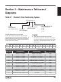
Section 2 – Maintenance Tables and Diagrams . . . . . . . . . . . . . . . . . . . . . . . . . . . . . . . . . 31
2.1 Standard Hose Numbering System ...................................................31
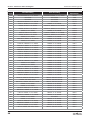
2.2 Torque Specifications for Fasteners (US) . . . . . . . . . . . . . . . . . . . . . . . . . . . . . . . . . . . . . . . . . . . . . . 33
Table of Contents

6
SJ3220, SJ3226, SJ4720, SJ4726, SJ4732223198AEA
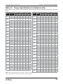
2.4 Torque Specifications for Fasteners (Metric) . . . . . . . . . . . . . . . . . . . . . . . . . . . . . . . . . . . . . . . . . . . .34
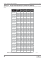
2.5 Torque Specifications for Hydraulic Couplings & Hoses . . . . . . . . . . . . . . . . . . . . . . . . . . . . . . . . . .35
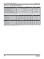
2.6 Torque Specifications ..............................................................36
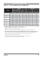
2.7 Floor Loading Pressure (ANSI/CSA) ..................................................37
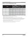
2.8 Floor Loading Pressure (CE) ........................................................38
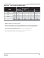
2.9 Floor Loading Pressure (AS) ........................................................39
2.10 Floor Loading Pressure (KC) ........................................................40
2.11 Specifications & Features - SJ3220 ...................................................41
2.12 Specifications & Features - SJ3226 ...................................................42
2.13 Specifications & Features - SJ4720 & SJ4726 . . . . . . . . . . . . . . . . . . . . . . . . . . . . . . . . . . . . . . . . . . . 43
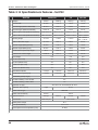
2.14 Specifications & Features - SJ4732 ...................................................44
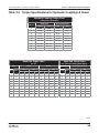
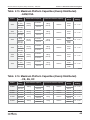
2.15 Maximum Platform Capacities (Evenly Distributed) - ANSI/CSA . . . . . . . . . . . . . . . . . . . . . . . . . . . .45
2.16 Maximum Platform Capacities (Evenly Distributed) - CE, AS, KC . . . . . . . . . . . . . . . . . . . . . . . . . . .45
Section 3 – System Component Identification and Schematics . . . . . . . . . . . . . . . . . . . . 47
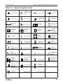
3.1 Electrical Symbol Chart .............................................................48
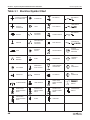
3.2 Hydraulic Symbol Chart ............................................................49
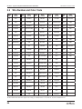
3.3 Wire Number and Color Code ........................................................50
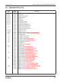
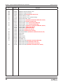
3.4 Hydraulic Parts List ................................................................51
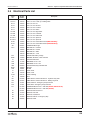
3.5 Electrical Parts List ................................................................53
3.6 Platform Control Box Wiring .........................................................55
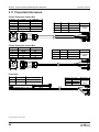
3.7 Platform Control Box Wiring - SGLE ..................................................56
3.8 Platform Control Box Wiring - ACPP ..................................................57
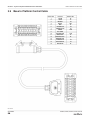
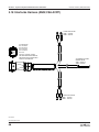
3.9 Base to Platform Control Cable ......................................................58
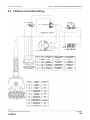
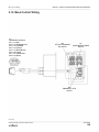
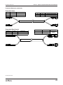
3.10 Base Control Wiring ...............................................................59
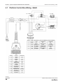
3.11 Base Control Wiring - ACPP .........................................................60
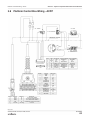
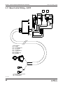
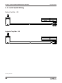
3.12 Emergency Lowering Switch Wiring ...................................................61
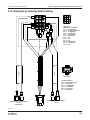
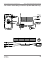
3.13 Limit Switch Wiring ................................................................62
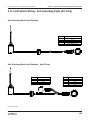
3.14 Limit Switch Wiring - Anti-Overrising Posts (KC Only) . . . . . . . . . . . . . . . . . . . . . . . . . . . . . . . . . . . . 63
3.15 Anti-Overrising Harnesses (KC Only). . . . . . . . . . . . . . . . . . . . . . . . . . . . . . . . . . . . . . . . . . . . . . . . . .64
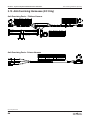
3.16 Electrical Harnesses ...............................................................65
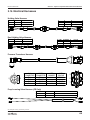
3.17 Powerdeck Harnesses. . . . . . . . . . . . . . . . . . . . . . . . . . . . . . . . . . . . . . . . . . . . . . . . . . . . . . . . . . . . . .66
3.18 Interlocks Harness (ANSI/CSA ACPP) .................................................68
3.19 Outdoor Switch Wiring and Harness (SJ3226 ANSI/CSA Only) . . . . . . . . . . . . . . . . . . . . . . . . . . . . .69
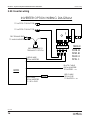
3.20 Inverter wiring ....................................................................70
3.21 Drive Manifold MB2 - SJ3220/26 & SJ4726/32 (ANSI/CSA) . . . . . . . . . . . . . . . . . . . . . . . . . . . . . . . .71
3.22 Drive Manifold MB2 - SJ3220/26 (CE, AS & KC) . . . . . . . . . . . . . . . . . . . . . . . . . . . . . . . . . . . . . . . . . 72
3.23 Drive Manifold MB2 - SJ4720/26/32 (CE, AS & KC) . . . . . . . . . . . . . . . . . . . . . . . . . . . . . . . . . . . . . . . 73
3.24 Brake Manifold MB6 - SJ4720/26/32 (CE, AS & KC) . . . . . . . . . . . . . . . . . . . . . . . . . . . . . . . . . . . . . . 73
3.25 Single Lift Cylinder Manifold MB5 - SJ3220, SJ4720 . . . . . . . . . . . . . . . . . . . . . . . . . . . . . . . . . . . . . 74
3.26 Dual Lift Cylinder Manifold MB3 & MB4 - SJ3226, SJ4726/32 . . . . . . . . . . . . . . . . . . . . . . . . . . . . . .75
3.27 Powerdeck Manifold MB1 - SJ3220, SJ4720 . . . . . . . . . . . . . . . . . . . . . . . . . . . . . . . . . . . . . . . . . . . .76
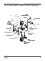
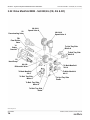
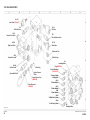
3.28 Major Component Identification ......................................................77

7
SJ3220, SJ3226, SJ4720, SJ4726, SJ4732 223198AEA
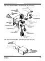
3.29 Main Manifold MB1 ................................................................78
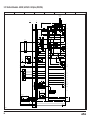
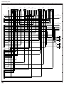
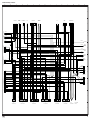
3.30 Hydraulic Schematics - SJ3220/26 ANSI/CSA . . . . . . . . . . . . . . . . . . . . . . . . . . . . . . . . . . . . . . . . . . .79
3.31 Hydraulic Schematics - SJ3220/26 CE .................................................80
3.32 Hydraulic Schematics - SJ3220/26 AS/KC . . . . . . . . . . . . . . . . . . . . . . . . . . . . . . . . . . . . . . . . . . . . . . 81
3.33 Hydraulic Schematics - SJ4720/26/32 ANSI/CSA . . . . . . . . . . . . . . . . . . . . . . . . . . . . . . . . . . . . . . . .82
3.34 Hydraulic Schematics - SJ4720/26/32 CE . . . . . . . . . . . . . . . . . . . . . . . . . . . . . . . . . . . . . . . . . . . . . .83
3.35 Hydraulic Schematics - SJ4720/26/32 AS/KC . . . . . . . . . . . . . . . . . . . . . . . . . . . . . . . . . . . . . . . . . . .84
3.36 Telematics Harness ................................................................85
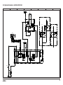
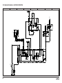
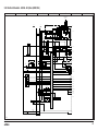
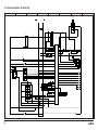
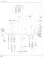
3.37 Electrical Schematic - SJ3220, SJ4726/32 - All Option (ANSI/CSA) . . . . . . . . . . . . . . . . . . . . . . . . . .86
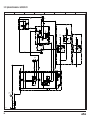
3.38 Electrical Schematic - SJ3226 - All Option (ANSI/CSA) . . . . . . . . . . . . . . . . . . . . . . . . . . . . . . . . . . .87
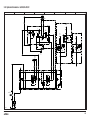
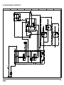
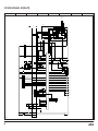
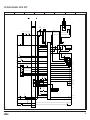
3.39 Electrical Schematic - All Option (CE) . . . . . . . . . . . . . . . . . . . . . . . . . . . . . . . . . . . . . . . . . . . . . . . . . 88
3.40 Electrical Schematic - All Option (AS) . . . . . . . . . . . . . . . . . . . . . . . . . . . . . . . . . . . . . . . . . . . . . . . . .89
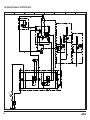
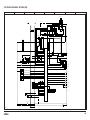
3.41 Electrical Schematic - All Option (KC) . . . . . . . . . . . . . . . . . . . . . . . . . . . . . . . . . . . . . . . . . . . . . . . . .90
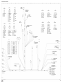
3.42 Electrical Schematic - SJ4726 - ACPP .................................................91
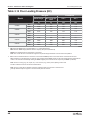
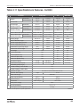
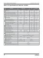
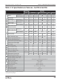
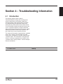
Section 4 – Troubleshooting Information . . . . . . . . . . . . . . . . . . . . . . . . . . . . . . . . . . . . . . 97
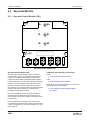
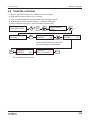
4.1 Introduction ......................................................................97
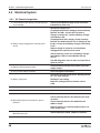
4.2 Electrical System ..................................................................98
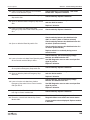
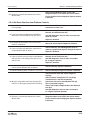
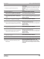
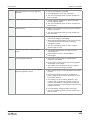
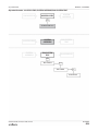
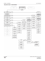
4.2-1 All Controls Inoperative ..........................................................98
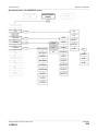
4.2-2 All Controls Except for Down Function Inoperative . . . . . . . . . . . . . . . . . . . . . . . . . . . . . . . . . . . 100
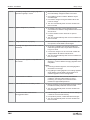
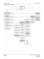
4.2-3 All Controls Inoperative From Base Control Console . . . . . . . . . . . . . . . . . . . . . . . . . . . . . . . . . . 101
4.2-4 No Up Function from Base Control Console . . . . . . . . . . . . . . . . . . . . . . . . . . . . . . . . . . . . . . . . 102
4.2-5 No Down Function from Base Control Console . . . . . . . . . . . . . . . . . . . . . . . . . . . . . . . . . . . . . . 103
4.2-6 No Emergency Down Function from Base Control Console*. . . . . . . . . . . . . . . . . . . . . . . . . . . . 104
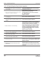
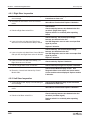
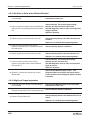
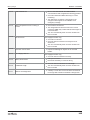
4.2-7 All Controls Inoperative From Platform Control Console . . . . . . . . . . . . . . . . . . . . . . . . . . . . . . . 105
4.2-8 No Up Function from Platform Controls (ANSI/CSA, CE, and AS) . . . . . . . . . . . . . . . . . . . . . . . . 108
4.2-9 No Up Function from Platform Controls (KC) . . . . . . . . . . . . . . . . . . . . . . . . . . . . . . . . . . . . . . . . 109
4.2-10 No Down Function from Platform Controls . . . . . . . . . . . . . . . . . . . . . . . . . . . . . . . . . . . . . . . . . . 111
4.2-11 Right Steer Inoperative .........................................................112
4.2-12 Left Steer Inoperative ..........................................................112
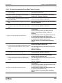
4.2-13 Forward Drive Function Inoperative . . . . . . . . . . . . . . . . . . . . . . . . . . . . . . . . . . . . . . . . . . . . . . . 113
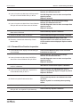
4.2-14 Reverse Drive Function Inoperative . . . . . . . . . . . . . . . . . . . . . . . . . . . . . . . . . . . . . . . . . . . . . . . 114
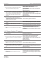
4.2-15 No Drive or Steer when Platform Elevated . . . . . . . . . . . . . . . . . . . . . . . . . . . . . . . . . . . . . . . . . . 116
4.2-16 High/Low Torque Inoperative ....................................................116
4.2-17 Pressure Transducer PT1 Inoperative . . . . . . . . . . . . . . . . . . . . . . . . . . . . . . . . . . . . . . . . . . . . . . 117
4.2-18 Angle Transducers AT1 and/or AT2 Inoperative . . . . . . . . . . . . . . . . . . . . . . . . . . . . . . . . . . . . . . 118
4.2-19 Power Deck Inoperative (if Option is installed) . . . . . . . . . . . . . . . . . . . . . . . . . . . . . . . . . . . . . . 118
4.3 Hydraulic System .................................................................120
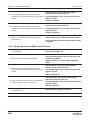
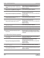
4.3-1 All Functions Inoperative ........................................................120
4.3-2 All System Sluggish ............................................................120
4.3-3 Platform Drifts Down ...........................................................120
4.3-4 Platform Lifts Slowly ...........................................................120
4.3-5 Platform Does Not Lift ..........................................................120

8
SJ3220, SJ3226, SJ4720, SJ4726, SJ4732223198AEA
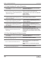
4.3-6 Platform Will Not Lower .........................................................121
4.3-7 Platform Drives Slow ...........................................................121
4.3-8 Platform Will Not Drive in Forward or Reverse . . . . . . . . . . . . . . . . . . . . . . . . . . . . . . . . . . . . . . . 121
4.3-9 Brake(s) will not Release (Pin Brakes) . . . . . . . . . . . . . . . . . . . . . . . . . . . . . . . . . . . . . . . . . . . . . 121
4.3-10 Brake(s) will not Release (Wet Brakes) . . . . . . . . . . . . . . . . . . . . . . . . . . . . . . . . . . . . . . . . . . . . . 122
4.3-11 MEWP will not hold on a Grade (Wet Brakes) . . . . . . . . . . . . . . . . . . . . . . . . . . . . . . . . . . . . . . . . 122
4.3-12 Platform does not Steer ........................................................122
4.3-13 High/Low Torque Inoperative ....................................................122
4.3-14 Platform Power Deck Inoperative (if option installed). . . . . . . . . . . . . . . . . . . . . . . . . . . . . . . . . . 122
Section 5 – Procedures ...................................................123
5.1 General .........................................................................123
5.1-1 Safety and Workmanship .......................................................123
5.2 Platform ........................................................................124
5.2-1 Single Axis Joystick ............................................................124
5.2-2 Gate Spring Hinge Adjustment ...................................................125
5.2-3 Platform Mounting Hardware ....................................................125
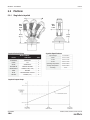
5.3 Base ...........................................................................126
5.3-1 System Relief Pressure Adjustment ...............................................126
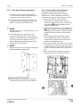
5.3-2 Pothole Compression Rod Replacement . . . . . . . . . . . . . . . . . . . . . . . . . . . . . . . . . . . . . . . . . . . 127
5.3-3 Replace and Adjust the Pothole Limit Switches (LS1 battery tray side & LS2 hydraulic tray
side) .......................................................................128
5.3-4 Pothole Bar Replacement/Removal for Servicing . . . . . . . . . . . . . . . . . . . . . . . . . . . . . . . . . . . . . 130
5.3-5 Tightening and Torque Recommendations for Hydraulic Couplings and Hoses . . . . . . . . . . . . 132
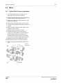
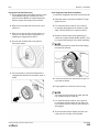
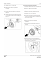
5.3-6 Integrated Hub Wheel Removal and Installation . . . . . . . . . . . . . . . . . . . . . . . . . . . . . . . . . . . . . . 134
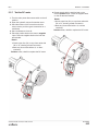
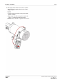
5.3-7 Test the DC motor .............................................................137
5.4 Battery Charger ..................................................................139
5.4-1 Battery service ...............................................................139
5.4-2 Charger Maintenance ..........................................................139
5.4-3 Charger Profiles ..............................................................140
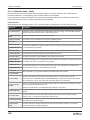
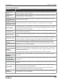
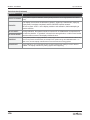
5.4-4 Charger Troubleshooting .......................................................141
5.4-5 Charger Fault Codes ...........................................................141
5.4-6 Charger Error Codes ...........................................................142
5.5 Skycoded Module ................................................................146
5.5-1 Skycoded Control Module (CM1) ................................................146
5.5-2 Calibration and Diagnostic Tool Key Functions . . . . . . . . . . . . . . . . . . . . . . . . . . . . . . . . . . . . . . 149
5.5-3 Diagnostics, Help Messages and Flash Codes . . . . . . . . . . . . . . . . . . . . . . . . . . . . . . . . . . . . . . 164
5.5-4 Override Mode Procedure ......................................................171
5.5-5 Initial Set-up and Change Defaults Procedure . . . . . . . . . . . . . . . . . . . . . . . . . . . . . . . . . . . . . . . 171
5.5-6 Access Levels Procedure .......................................................172
5.5-7 Calibrate Level Procedure ......................................................172
5.5-8 Calibrate Load Procedure .......................................................173
5.5-9 Language Setting Procedure ....................................................175
5.5-10 All Motion Alarm ..............................................................175

9
SJ3220, SJ3226, SJ4720, SJ4726, SJ4732 223198AEA
5.5-11 Calibration Load - Faults ........................................................176
5.6 Flash the controller ...............................................................179

10
SJ3220, SJ3226, SJ4720, SJ4726, SJ4732223198AEA
Notes

11
SJ3220, SJ3226, SJ4720, SJ4726, SJ4732 223198AEA
Section 1 – Maintenance
1.1 Read and Heed
Skyjack is continuously improving and expanding
product features on its equipment; therefore,
specifications and dimensions are subject to change
without notice.
1.1-1 Mobile Elevating Work Platform
(MEWP) definition
A MEWP is a mobile machine intended for moving
persons, tools, and material to working positions. It
consists of a work platform with controls, an extending
structure, and a chassis.
1.1-2 Purpose of equipment
The Skyjack DC Electric Scissor lifts are designed
to move personnel, tools, and materials to working
positions.
1.1-3 Use of equipment
The MEWP is a highly maneuverable, mobile work
station. Only elevate the platform, or drive while
elevated on a firm, level surface.
1.1-4 Service Policy and Warranty
Skyjack warrants each new product to be free of
defective parts and workmanship for the first 2 years
or 3000 hours, whichever occurs first. Your local
Skyjack dealer will replace or repair any defective
part, with no charge for parts or labour. In addition, all
products have a 5-year structural warranty. Contact
the Skyjack service department for warranty statement
extensions or exclusions.
1.1-5 Ownership of MEWP
Notify Skyjack of MEWP ownership. If you sell or
transfer the ownership of a MEWP, promptly notify
Skyjack of the new owner’s contact information.
Skyjack needs this information to inform the owner of
any updates or additional activities that are necessary
to keep the machine in proper working condition.
1.1-6 Optional equipment
This MEWP accepts a variety of optional equipment.
Refer to the operation manual for a list of the optional
accessories. Operating instructions for these options
are in the operation manual.
For components or systems that are not standard,
speak to the Skyjack service department. Give the
model and serial number for each applicable MEWP.

12
SJ3220, SJ3226, SJ4720, SJ4726, SJ4732223198AEA
Section 1 – Maintenance General information
1.2 General information
1.2-1 Owner’s annual inspection record
The owner is responsible for the maintenance
inspections and repairs. Keep a record of the annual
inspection on the label on the scissor stack. Refer to
1.4 Owner’s Annual Inspection Record.
1.2-2 Replacement parts
Use only original replacement parts. Parts such
as batteries, wheels, railings, etc. with weights and
dimensions different from the original parts will affect
the stability of the MEWP. They must not be used
without the manufacturer’s consent.
All replacement tires must be of the same size and
load rating as the originally supplied tires to maintain
the safety and stability of the MEWP.
WARNING
A unit that is damaged or not operating correctly
must be immediately tagged and removed from
service until repairs are completed.
1.2-3 Maintenance and service safety tips
1. Maintenance and repair should only be done
by personnel who are trained and qualified to
service this MEWP.
2. Do the maintenance and service procedures in a
well-lit and well-ventilated area.
3. Anyone operating or servicing this MEWP
must read and fully understand all operating
instructions and safety hazards in both this
manual and the operation manual.
4. Make sure all tools, supports, and lifting
equipment are of the correct rated load and in
good working condition.
5. Keep the work area clean and free of debris to
avoid component contamination.
6. Make sure personnel are not below unsupported
components or systems that are at risk of
movement during maintenance.
7. All service personnel must be familiar with the
employer and governmental regulations for
servicing this type of equipment.
8. Keep sparks and flames away from flammable or
combustible materials.
9. Correctly dispose of waste material such as
lubricants, rags, and old parts in accordance
with national, state/provincial/territorial, and local
regulations.
10. Before you do any repair work, disconnect the
main power connectors.

13
SJ3220, SJ3226, SJ4720, SJ4726, SJ4732 223198AEA
General information Section 1 – Maintenance
1.2-4 Hydraulic system & component
maintenance and repair
WARNING
The fluid which escapes from a high-pressure
hydraulic leak can damage your eyes, penetrate
your skin, and cause serious injury. Wear the
correct personal protective equipment at all times.
1. The hydraulic circuits include relief valves
which limit pressure to safe operation values.
They help to prevent the failure of hydraulic or
structural components.
2. Make sure the hydraulic oil is completely
clean. Even small amounts of dirt or
unwanted materials in the system can damage
components and cause unsatisfactory operation
of the hydraulic system.
3. Drain and flush the entire system and replace
the filter cartridges if you have any reason to
believe there is contamination of the hydraulic
system, or hydraulic system failure.
4. When you drain the hydraulic system, check
the magnets in the hydraulic tank for metal
particles. Metal particles can indicate imminent
component failure. If metal particles are present,
flush the entire system and change the hydraulic
oil.
5. All containers and funnels used in handling the
hydraulic oil must be completely clean. Use a
funnel when necessary and fill the reservoir only
through the filter opening. Do not use a cloth to
strain the oil, as lint could get into the system.
6. When you remove a hydraulic component, cap
and tag all of the hydraulic lines involved. Plug
the ports of the removed components.
7. Disassemble hydraulic components in clean
surroundings. Carefully identify the parts to
make sure you reassemble them correctly. Clean
all metal parts in a clean mineral oil solvent. Be
sure to clean all internal passages fully. After
the parts are dry, lay them on a clean, lint-free
surface for inspection.
8. Replace all O-rings and seals when you overhaul
a component. Lubricate all parts with clean
hydraulic oil before you reassemble them. Use a
small amount of petroleum jelly to hold O-rings
in place during assembly.
9. Be sure to replace lost hydraulic oil after you
install the repaired component. Bleed air from
the system when required.
10. Keep all hydraulic connections tight. A loose
connection in a pressure line allows the oil
to leak or draw air into the system. Air in the
system can damage components and cause
noisy or erratic system operation.
11. Preventive maintenance is the easiest and least
expensive type of maintenance.
1.2-5 Hydraulic oil maintenance
Draw samples of hydraulic oil from the reservior
annually and test them.
▪Take these samples when the oil is warmed
through normal operation of the system.
▪Have the sample analyzed by a qualified
lubrication specialist to determine if it is suitable
for continued use.
Oil change intervals depend on the care used to keep
the oil clean, and the operating conditions.
▪Oil must be changed more often when there is
dirt or moisture contamination.
▪Under normal use and operating conditions, you
should change the hydraulic oil every two years.
Refer to Table 1.5 Frequent/Periodic/Annual/Pre-
Delivery Inspection Checklist of this manual.
1.2-6 Hydraulic maintenance tips
1. Change the filters annually. Dirty, dusty, and
high-moisture environments can cause the
hydraulic system to be contaminated more
quickly. You may need to change the filters
more often.
2. Keep a sufficient quantity of clean hydraulic oil
of the correct type and viscosity in the hydraulic
tank.
3. Keep all hydraulic connections tight.

14
SJ3220, SJ3226, SJ4720, SJ4726, SJ4732223198AEA
Section 1 – Maintenance Scheduled maintenance and inspections
1.2-7 Railing maintenance and repair
Skyjack MEWPs have been designed to ensure
compliance with the relevant design standards
applicable for that particular unit at the time of
manufacture. As such, any repairs made to the
guardrail or basket structure need to ensure this
compliance is not compromised and must return the
structure to its original condition.
Any damage must be repaired by returning the railing
assembly to its undamaged state. Damage includes,
but is not limited to, the items listed below:
▪bent/deformed guardrail sections
▪cracks or broken welds in railing sections
▪damaged pin connections
▪missing pins or broken pin lanyards
▪missing railing hardware
▪loose or missing parts
▪additional holes in guardrail sections other than
those approved by Skyjack
Additionally, the guardrails must be properly
positioned and secured, and the entry gate must be
in good working order.
The strength of the guardrail system, and therefore
its ability to provide fall protection for platform
occupants, depends upon the design being secure
and undamaged.
Skyjack railings are designed for modular
replacement, and Skyjack recommends replacement
of any damaged railing section. Skyjack-approved
replacement parts will meet this requirement.
1.2-8 Multi-conduction control cable
repair
If damage occurs to the outer casing of a multi-
conductor control cable, you may use heat shrink
tubing to case and protect the control cable casing.
Before you install the heat shrink, make sure there is
no damage to the individual wires contained in the
control cable, or to their insulation.
The heat shrink tubing selected and used should seal
the electrical circuit from water intrusion, be suitable
for the machine operating temperature range, and be
suitably flexible to allow the required bending radius
of the cable in its application.
1.3 Scheduled maintenance
and inspections
1.3-1 Service bulletins
Before performing any scheduled maintenance
inspection procedure, refer to the service bulletins
found on our website: www.skyjack.com for updates
related to the service and maintenance of this MEWP.
1.3-2 Maintenance and inspections
Death or injury can result if the MEWP is not kept in
good working order. Inspection and maintenance
should be done by competent personnel who are
trained and qualified on maintenance of this MEWP.
WARNING
Failure to perform each procedure as presented
and scheduled may cause death, serious injury, or
substantial damage.
NOTE
Preventive maintenance is the easiest and least
expensive type of maintenance.
▪Unless otherwise specified, do each
maintenance procedure with the MEWP in the
following configuration:
▪Park the MEWP on a flat and level surface
▪Disconnect the batteries by disconnecting the
main power connectors.
▪Repair damaged or malfunctioning components
before operating the MEWP.
▪Keep records of all inspections.

15
SJ3220, SJ3226, SJ4720, SJ4726, SJ4732 223198AEA
Scheduled maintenance and inspections Section 1 – Maintenance
1.3-3 Schedule and instructions
The actual operating environment of the MEWP may
affect the maintenance schedule.
The inspection points covered in the 1.5 Frequent/
Periodic/Annual/Pre-Delivery Inspection Checklist
indicate the areas of the MEWP to be maintained or
inspected, and at what intervals the maintenance and
inspections are to be done.
Inspection schedule frequency:
PDI/Frequent/
Periodic B
Do a PDI before each
delivery, or a Frequent
Inspection every 200 days
or 200 hours.
Annual C
Do a Scheduled
Maintenance Inspection
every year.
Additional *Do this at time-sensitive
maintenance intervals.
▪Make copies of the maintenance and inspection
checklist to be used for each inspection.
▪Check the schedule on the checklist for the type
of inspection to be done.
▪Place a check mark in the appropriate box after
each inspection procedure is done.
▪Use the maintenance and inspection checklist
and the step-by-step procedures in 1.6
Scheduled maintenance inspections.
▪If an inspection receives a fail, tag and remove
the MEWP from service.
▪If a MEWP components has been repaired, do
an inspection again before you remove the tag.
Place a check mark in the repair column.
Legend
Pass P
Not applicable N/A
1.3-4 Function tests
Function tests are designed to discover malfunctions
before a MEWP is put into service.
Refer to the “Inspections before operation” section of
the operation manual for detailed instructions on how
to do the function tests.
IMPORTANT
Never use a malfunctioning MEWP. If malfunctions are
discovered, tag the MEWP and remove it from service.
1.3-5 Repairs
When repairs are made to a MEWP, the service
technician must complete the full pre-operation
inspection and function tests before putting the MEWP
into service.

16
SJ3220, SJ3226, SJ4720, SJ4726, SJ4732223198AEA
Section 1 – Maintenance Owner’s Annual Inspection Record
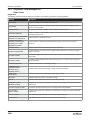
1.4 Owner’s Annual Inspection RecordTable
Inspection
Date
Inspector
Signature
WARNING
Do not use the MEWP if there is no inspection
recorded in the last 13 months. If you do not obey,
there is a risk of death or serious injury.
IMPORTANT
The Owner’s annual inspection record is located
on the scissor assembly. It must be filled out after
an annual inspection has been completed. Do
not use the MEWP if an inspection has not been
recorded in the last 13 months.

17
SJ3220, SJ3226, SJ4720, SJ4726, SJ4732 223198AEA
Frequent/Periodic/Annual/Pre-Delivery Inspection Checklist Section 1 – Maintenance
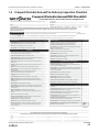
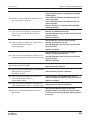
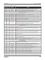
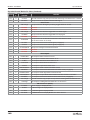
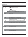
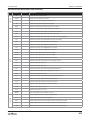
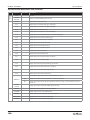
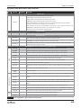
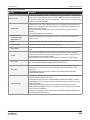
1.5 Frequent/Periodic/Annual/Pre-Delivery Inspection Checklist
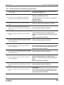
Frequent/Periodic/Annual/PDI Checklist
Vertical Mast, Electric Scissor, Micro Scissor & Rough Terrain
Serial Number: Starting with serial number A/B000 000 000 or 09 000 000 and above
Use this table for pre-delivery inspections (PDI) before each rental, lease or sale and as an instruction for all frequent inspections and annual inspections.
Refer to the operation and service manuals for inspection instructions (for example, visual inspection and function tests, torque specs, engine oil, chain
inspection intervals, and more).
B - Do the pre-delivery inspection before the machine is sent out or during the frequent inspections at 200 days or 200 hour
intervals. For more instructions, refer to the operation and service manuals.
C - Do the scheduled maintenance Inspections each year. For more instructions, refer to the operation and service manuals.
P - Pass
N/A - Not Applicable
Put a check mark on the “Pass” column as you meet the requirements of the inspection of each item. Add a comment if the item does not pass inspection.
Model:
Hourmeter Reading:
Date/Time:
Inspection Type (Choose one): Pre-delivery Frequent Periodic Annual
Product User:
Product Owner:
Inspection Type Schedule
PDI/Frequent/Periodic B
Annual B+C
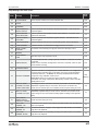
Items for Inspection P N/A
Service Bulletins. Make sure there are no open service bulletins. B
Annual Inspection. Make sure you complete it within 13 months. B
Labels. In place, correctly attached & you can read them. B
Limit Switches. Correctly installed & no obstructions or damage. B
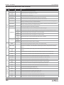
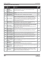
BASE/ENGINE
Engine and Components. Do a check on engine and components for any
loose, missing, damaged, or failed items. Make sure you do not exceed the
recommended uid, oil and coolant change intervals.
B
Engine and Components. Replace the engine oil and lter. C
Engine Intake Air Filter. No damage or missing component. Remove dirt & dust. B
Engine Intake Air Filter. Replace the air lter if necessary. C
Engine Oil. Oil level between “L” and “H”. Make sure you do not exceed the oil
change interval. B
Radiator. Correctly attached & no damage or missing components. Do a check
of coolant level. B
Radiator. Do a check of coolant level & condition & replace if necessary. C
Fuel Tank & Lines. Filler cap, tank, ttings and hoses are tightly closed & no
damage or leaks. B
Propane Tank & Lines. Straps are correctly installed to brackets &
couplers are tight. Make sure there are no damage or leaks. B
Outriggers. No damage or missing components. B
Pothole Protection. Both sides have no obstructions, dirt or damage. B
Battery/Hydraulic Tray. Trays are latched tightly & no missing components. B
Batteries. No damage, tight connections & sufcient uid levels. Clean terminals
and cable ends. B
Battery Charger. Correctly attached & no damage. B
Steer Assembly. Correctly attached & no damage leaks or missing components. B
Wheel/Tire Assembly. Do a check of all tires for damage, missing parts, wear &
correctly aligned. B
Wheel/Tire Assembly. Wheel nuts torqued as recommended. C
Axles. Correctly attached & no missing components. Tight ttings and hoses &
no leaks. B
Axles. Do a check and replace oil if necessary. C
Hydraulic Tank, Pump, Motor & Lines. Filler cap, hoses, and other hydraulic
components are closed tightly & no damage or leaks. B
Hydraulic Oil. Level at, or slightly above top mark. B
Hydraulic Oil. Do a check and replace oil and lters if necessary. C
Electrical Components. Do a check on all electrical components such as the
motor controller if necessary. Correctly attached & no damage. Tight wire con-
nections and fasteners.
B
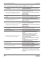
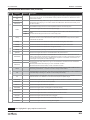
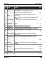
Items for Inspection P N/A
Manifolds. Tight ttings and hoses & no damage or leaks. Tight wire
connections, no missing components & correctly working valves. B
Main Power Disconnect Switch. Cables tight & in working order. B
Base Controls. Operate switches and make sure they all operate correctly. No
damage or missing components. B
Brakes. Correctly attached & no damage or leaks. B
Brakes. Do a check on disc wear and replace if necessary. C
Base Weldment. No deformation or cracks. B
Grease Points. No obstructions, dirt, or damage. Add grease if necessary. B
Ladder. Correctly attached & no damage. B
Tilt Sensor. Correctly attached & no damage. B
LIFTING MECHANISM - MAST/SCISSORS
Maintenance Support(s). Correctly attached & no damage. B
Scissor Assembly & Bumpers. Correctly attached, no deformation/damage.
Cables & wires installed with no damage. B
Sliders & Rollers. Correctly attached & no obstructions, dirt, or damage/wear. B
Lift Cylinder(s). No damage or missing components. Tight ttings and hoses &
no leaks. Correctly installed. B
Angle Transducer. Correctly attached & no damage. B
Scissor Pins. Correctly attached & no damage. B
Mast Assembly. No damage, cracks or deformation. B
Mast Assembly. Lubricate the mast as recommended. C
Chains, Rollers & Control Cables. No damage or missing components. B
Wear Pads. No damage/wear or missing components. Fasteners tight. B
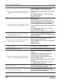
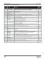
PLATFORM
Railings and Gate. Correctly attached & no damage or missing
components. B
Fall-Protection Anchorage. Attachment rings correctly attached & no damage. B
AC Power Socket. No obstructions, dirt, or damage. B
Platform Control Console. Operate the switches and make sure they all
operate correctly. No damage or missing components. B
Manual Storage Box. Manuals and documents are in the storage the box, in
good condition, and you can read them. B
Powered Extension Control Console. Operate switches and make sure they
all operate correctly. No damage or missing components. B
Extension Platform. Correctly attached & no damage or missing components. B
Function Tests. Refer to the operation manual for your serial number for
information on how to run these tests.
PASS
FAIL
Comments:
Print Name
Print Name
Owner:
User:
199341ADA
Signature
Signature
Date (DD/MM/YY)
Date (DD/MM/YY)
The undersigned has made sure that all areas in the list have received an inspection.
The undersigned has told the machine owner of all inconsistencies in the inspection and corrected them before machine operation.

18
SJ3220, SJ3226, SJ4720, SJ4726, SJ4732223198AEA
Section 1 – Maintenance Scheduled maintenance inspections
1
1
1.6 Scheduled maintenance
inspections
Do an inspection of the MEWP in this sequence:
WARNING
Do not operate a MEWP that does not function
correctly. Lock and tag the MEWP, and remove it
for servicing. Only a qualified service technician
must repair the MEWP. If you do not obey, there is
a risk of death or serious injury.
WARNING
Turn the main power disconnect switch to the
off position before you do the visual and daily
maintenance inspections. If you do not obey, there
is a risk of death or serious injury.
CAUTION
Make sure that the MEWP is on a firm, level
surface before you do the visual and daily
maintenance inspections. If you do not obey, there
is a risk of machine damage.
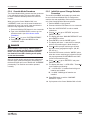
1.6-1 Service Bulletins
(B) Go to www.skyjack.com and use your machine’s
serial number to find related open service bulletins.
1.6-2 Annual Inspections
(B) Do a check on the machine’s service record to
find information about previous service performed.
1.6-3 Labels
(B) Refer to the operation manual for the labels. Make
sure all the labels are in the correct location, are in
good condition, and you can read them.
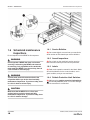
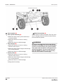
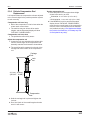
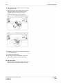
1.6-4 Pothole Protection Limit Switches
(B) Make sure the pothole protection limit switches
1 are correctly attached, there is no visible damage,
and the movement is not blocked.

19
SJ3220, SJ3226, SJ4720, SJ4726, SJ4732 223198AEA
Base Inspection Section 1 – Maintenance
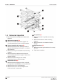
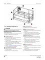
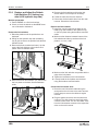
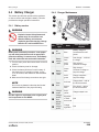
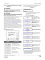
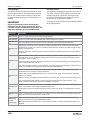
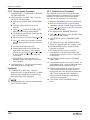
1.7 Base Inspection
1 Pothole protection device (B)
▪Make sure there are no loose or missing parts.
▪Make sure there is no visible damage.
▪Make sure there is no dirt and blockages.
2 Hydraulic and electric tray (B)
▪Make sure that the hydraulic and electric tray
latches correctly and is in good condition.
3 Battery tray (B)
▪Make sure that the battery tray latches correctly
and is in good condition.
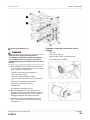
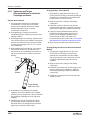
4 Batteries (B)
WARNING
Explosion hazard. Keep flames and sparks away.
Do not smoke near the batteries. Batteries release
explosive gas while you charge them. Charge the
batteries in a well-ventilated area. If you do not
obey, there is a risk of death or serious injury.
WARNING
Corrosion hazard. Do not touch battery acid. Wear
the correct PPE. If the battery acid touches you,
immediately flush the area with cold water and get
medical aid.
1. Do an inspection of the battery case for
damage.
2. Make sure all the battery connections are tight.
3. Clean the battery terminals and cable ends
thoroughly with a terminal cleaning tool or wire
brush.
4. If applicable, do a check on the battery fluid
levels. If the plates do not have a minimum
13 mm (1/2 inch) of solution above them, add
distilled or demineralized water.
5. Replace the battery if damaged or not able to
hold a lasting charge.
WARNING
Only use original or manufacturer-approved parts
and components for the MEWP. If you do not obey,
there is a risk of death, serious injury, or machine
damage.
5 Battery charger (B)
▪Make sure that the battery charger is correctly
installed, and in good condition.
▪Make sure there is no visible damage.
145
3
12
Example model SJ4732 Battery Tray Example model SJ4732 Hydraulic Tray

20
SJ3220, SJ3226, SJ4720, SJ4726, SJ4732223198AEA
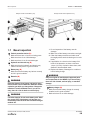
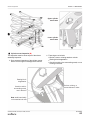
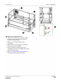
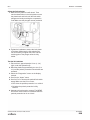
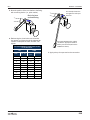
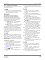
Section 1 – Maintenance Base Inspection
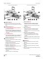
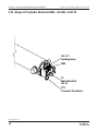
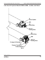
1 Steer assembly (B)
▪Steer cylinder assembly (B)
▪Make sure that the steer cylinder assembly is
correctly installed.
▪Make sure there are no loose or missing
fasteners.
▪Make sure there is no visible damage.
▪Steer linkages (B)
▪Make sure there are no loose or missing
fasteners and lock-pins.
▪Make sure that the steer linkages and bushings
are correctly attached.
▪Make sure there is no visible damage.
▪Grease points (B)
▪Make sure there are no loose or missing
fasteners and lock-pins.
▪Make sure that the steer linkages and bushings
are correctly attached.
▪Make sure there is no visible damage.
▪Add grease if necessary.
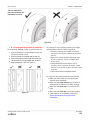
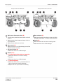
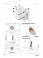
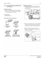
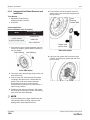
2 Wheel/tire assembly (B)
A small amount of wear is permitted. But if any of the
wear or damage meets the criteria mentioned below,
the tire should be replaced.
WARNING
Do not use tires other than the tires that Skyjack
specifies for this MEWP. Do not mix different types
of tires or use tires that are not in good condition.
Only replace the tires with the same types that are
approved by Skyjack. The use of other tires can
make the MEWP less stable. If you do not obey,
there is a risk of death or serious injury.
Example model SJ4732
112 2
1 11
Page is loading ...
Page is loading ...
Page is loading ...
Page is loading ...
Page is loading ...
Page is loading ...
Page is loading ...
Page is loading ...
Page is loading ...
Page is loading ...
Page is loading ...
Page is loading ...
Page is loading ...
Page is loading ...
Page is loading ...
Page is loading ...
Page is loading ...
Page is loading ...
Page is loading ...
Page is loading ...
Page is loading ...
Page is loading ...
Page is loading ...
Page is loading ...
Page is loading ...
Page is loading ...
Page is loading ...
Page is loading ...
Page is loading ...
Page is loading ...
Page is loading ...
Page is loading ...
Page is loading ...
Page is loading ...
Page is loading ...
Page is loading ...
Page is loading ...
Page is loading ...
Page is loading ...
Page is loading ...
Page is loading ...
Page is loading ...
Page is loading ...
Page is loading ...
Page is loading ...
Page is loading ...
Page is loading ...
Page is loading ...
Page is loading ...
Page is loading ...
Page is loading ...
Page is loading ...
Page is loading ...
Page is loading ...
Page is loading ...
Page is loading ...
Page is loading ...
Page is loading ...
Page is loading ...
Page is loading ...
Page is loading ...
Page is loading ...
Page is loading ...
Page is loading ...
Page is loading ...
Page is loading ...
Page is loading ...
Page is loading ...
Page is loading ...
Page is loading ...
Page is loading ...
Page is loading ...
Page is loading ...
Page is loading ...
Page is loading ...
Page is loading ...
Page is loading ...
Page is loading ...
Page is loading ...
Page is loading ...
Page is loading ...
Page is loading ...
Page is loading ...
Page is loading ...
Page is loading ...
Page is loading ...
Page is loading ...
Page is loading ...
Page is loading ...
Page is loading ...
Page is loading ...
Page is loading ...
Page is loading ...
Page is loading ...
Page is loading ...
Page is loading ...
Page is loading ...
Page is loading ...
Page is loading ...
Page is loading ...
Page is loading ...
Page is loading ...
Page is loading ...
Page is loading ...
Page is loading ...
Page is loading ...
Page is loading ...
Page is loading ...
Page is loading ...
Page is loading ...
Page is loading ...
Page is loading ...
Page is loading ...
Page is loading ...
Page is loading ...
Page is loading ...
Page is loading ...
Page is loading ...
Page is loading ...
Page is loading ...
Page is loading ...
Page is loading ...
Page is loading ...
Page is loading ...
Page is loading ...
Page is loading ...
Page is loading ...
Page is loading ...
Page is loading ...
Page is loading ...
Page is loading ...
Page is loading ...
Page is loading ...
Page is loading ...
Page is loading ...
Page is loading ...
Page is loading ...
Page is loading ...
Page is loading ...
Page is loading ...
Page is loading ...
Page is loading ...
Page is loading ...
Page is loading ...
Page is loading ...
Page is loading ...
Page is loading ...
Page is loading ...
Page is loading ...
Page is loading ...
Page is loading ...
Page is loading ...
Page is loading ...
Page is loading ...
Page is loading ...
Page is loading ...
Page is loading ...
Page is loading ...
Page is loading ...
Page is loading ...
Page is loading ...
Page is loading ...
-
 1
1
-
 2
2
-
 3
3
-
 4
4
-
 5
5
-
 6
6
-
 7
7
-
 8
8
-
 9
9
-
 10
10
-
 11
11
-
 12
12
-
 13
13
-
 14
14
-
 15
15
-
 16
16
-
 17
17
-
 18
18
-
 19
19
-
 20
20
-
 21
21
-
 22
22
-
 23
23
-
 24
24
-
 25
25
-
 26
26
-
 27
27
-
 28
28
-
 29
29
-
 30
30
-
 31
31
-
 32
32
-
 33
33
-
 34
34
-
 35
35
-
 36
36
-
 37
37
-
 38
38
-
 39
39
-
 40
40
-
 41
41
-
 42
42
-
 43
43
-
 44
44
-
 45
45
-
 46
46
-
 47
47
-
 48
48
-
 49
49
-
 50
50
-
 51
51
-
 52
52
-
 53
53
-
 54
54
-
 55
55
-
 56
56
-
 57
57
-
 58
58
-
 59
59
-
 60
60
-
 61
61
-
 62
62
-
 63
63
-
 64
64
-
 65
65
-
 66
66
-
 67
67
-
 68
68
-
 69
69
-
 70
70
-
 71
71
-
 72
72
-
 73
73
-
 74
74
-
 75
75
-
 76
76
-
 77
77
-
 78
78
-
 79
79
-
 80
80
-
 81
81
-
 82
82
-
 83
83
-
 84
84
-
 85
85
-
 86
86
-
 87
87
-
 88
88
-
 89
89
-
 90
90
-
 91
91
-
 92
92
-
 93
93
-
 94
94
-
 95
95
-
 96
96
-
 97
97
-
 98
98
-
 99
99
-
 100
100
-
 101
101
-
 102
102
-
 103
103
-
 104
104
-
 105
105
-
 106
106
-
 107
107
-
 108
108
-
 109
109
-
 110
110
-
 111
111
-
 112
112
-
 113
113
-
 114
114
-
 115
115
-
 116
116
-
 117
117
-
 118
118
-
 119
119
-
 120
120
-
 121
121
-
 122
122
-
 123
123
-
 124
124
-
 125
125
-
 126
126
-
 127
127
-
 128
128
-
 129
129
-
 130
130
-
 131
131
-
 132
132
-
 133
133
-
 134
134
-
 135
135
-
 136
136
-
 137
137
-
 138
138
-
 139
139
-
 140
140
-
 141
141
-
 142
142
-
 143
143
-
 144
144
-
 145
145
-
 146
146
-
 147
147
-
 148
148
-
 149
149
-
 150
150
-
 151
151
-
 152
152
-
 153
153
-
 154
154
-
 155
155
-
 156
156
-
 157
157
-
 158
158
-
 159
159
-
 160
160
-
 161
161
-
 162
162
-
 163
163
-
 164
164
-
 165
165
-
 166
166
-
 167
167
-
 168
168
-
 169
169
-
 170
170
-
 171
171
-
 172
172
-
 173
173
-
 174
174
-
 175
175
-
 176
176
-
 177
177
-
 178
178
-
 179
179
-
 180
180
-
 181
181
-
 182
182


Skyjack SJ4726 User manual
- Type
- User manual
Ask a question and I''ll find the answer in the document
Finding information in a document is now easier with AI
Related papers
-
Skyjack SJ4740 User manual
-
Skyjack SJ12 User manual
-
-
-
-
-
-
-
-
Other documents
-
 Oshkosh Corporation JLG 660SJC Operation And Safety Manual
-
JLG 660SJ Operation And Safety Manual
-
Mec 3084ES - CE Operating instructions
-
-
-
-
-
-
-
ICM Controls ICM334 Application/Install Guide
