Maytag APH16 H Series Installation Instructions Manual
- Category
- Split-system air conditioners
- Type
- Installation Instructions Manual

Goodman Company, L.P.
5151 San Felipe, Suite 500, Houston, TX 77056
www.amana-hac.com
© 2015-2018 Goodman Company, L.P.
IOA-3011D
02/2018
I
NSTALLATION
I
NSTRUCTIONS
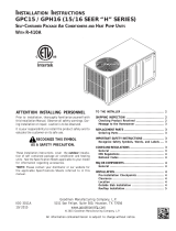
APC15 / APH 16 [15/16 SEER “H” SERIES]
SELF-CONTAINED PACKAGE AIR CONDITIONERS AND HEAT PUMP UNITS
WITH R-410A
ATTENTION INSTALLING PERSONNEL
Prior to installation, thoroughly familiarize yourself with this
Installation Manual. Observe all safety warnings. During in-
stallation or repair, caution is to be observed.
It is your responsibility to install the product safely and to
educate the customer on its safe use.
RECOGNIZE THIS SYMBOL
AS A SAFETY PRECAUTION.
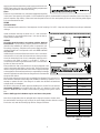
These installation instructions cover the outdoor installation
of self contained package air conditioner and heating units. See
the Specification Sheets applicable to your model for informa-
tion regarding accessories.
*NOTE: Please contact your distributor or our website for the
applicable Specifications Sheets referred to in this manual.
All information contained herein is subject to change without notice.
is a registered trademark of Maytag Corporation or its related companies and is used under license to Goodman Company, L.P., Houston, TX, USA. All rights reserved.
“IMPORTANT - This product has been designed and manufactured to meet ENERGY STAR®
criteria for energy efficiency when matched with appropriate coil components. However,
proper refrigerant charge and proper air flow are critical to achieve rated capacity and
efficiency. Installation of this product should follow the manufacturer’s refrigerant charging
and air flow instructions. Failure to confirm proper charge and air flow may reduce energy
efficiency and shorten equipment life.”
O
NLY
PERSONNEL
THAT
HAVE
BEEN
TRAINED
TO
INSTALL
,
ADJUST
,
SERVICE
OR
REPAIR
(
HEREINAFTER
, “
SERVICE
”)
THE
EQUIPMENT
SPECIFIED
IN
THIS
MANUAL
SHOULD
SERVICE
THE
EQUIPMENT
. T
HE
MANUFACTURER
WILL
NOT
BE
RESPONSIBLE
FOR
ANY
INJURY
OR
PROPERTY
DAMAGE
ARISING
FROM
IMPROPER
SERVICE
OR
SERVICE
PROCEDURES
. I
F
YOU
SERVICE
THIS
UNIT
,
YOU
ASSUME
RESPONSIBILITY
FOR
ANY
INJURY
OR
PROPERTY
DAMAGE
WHICH
MAY
RESULT
. I
N
ADDITION
,
IN
JURISDICTIONS
THAT
REQUIRE
ONE
OR
MORE
LICENSES
TO
SERVICE
THE
EQUIPMENT
SPECIFIED
IN
THIS
MANUAL
,
ONLY
LICENSED
PERSONNEL
SHOULD
SERVICE
THE
EQUIPMENT
. I
MPROPER
INSTALLATION
,
ADJUSTMENT
,
SERVICING
OR
REPAIR
OF
THE
EQUIPMENT
SPECIFIED
IN
THIS
MANUAL
,
OR
ATTEMPTING
TO
INSTALL
,
ADJUST
,
SERVICE
OR
REPAIR
THE
EQUIPMENT
SPECIFIED
IN
THIS
MANUAL
WITHOUT
PROPER
TRAINING
MAY
RESULT
IN
PRODUCT
DAMAGE
,
PROPERTY
DAMAGE
,
PERSONAL
INJURY
OR
DEATH
.

2
TROUBLESHOOTING CHART................................................ 16
START-UP CHECKLIST .......................................................... 18
T
O THE INSTALLER
Carefully read all instructions for the installation prior to installing
unit. Make sure each step or procedure is understood and any spe-
cial considerations are taken into account before starting installa-
tion. Assemble all tools, hardware and supplies needed to com-
plete the installation. Some items may need to be purchased lo-
cally. After deciding where to install unit, closely look the location
over - both the inside and outside of home. Note any potential ob-
stacles or problems that might be encountered as noted in this
manual. Choose a more suitable location if necessary.
IMPORTANT NOTE: If a crankcase heater is used, the unit should
be energized 24 hours prior to compressor start up to ensure crank-
case heater has sufficiently warmed the compressor. Compressor
damage may occur if this step is not followed.
Before using this manual, check the serial plate for proper model
identification.
The installation and servicing of this equipment must be performed
by qualified, experienced technicians only.
SHIPPING INSPECTION
Checking Product Received
Upon receiving the unit, inspect it for damage from shipment.
Claims for damage, either shipping or concealed, should be
filed immediately with the shipping company. Check the unit
model number, specifications, electrical characteristics and
accessories to determine if they are correct. In the event an
incorrect unit is shipped, it must be returned to the supplier
and must NOT be installed. The manufacturer assumes no
responsibility for installation of incorrectly shipped units.
Message to the Homeowner
These instructions are addressed primarily to the installer;
however, useful maintenance information is included and
should be kept, after installation, for future reference.
REPLACEMENT PARTS
Ordering Parts
When reporting shortages or damages, or ordering repair parts,
give the complete unit model and serial numbers as stamped
on the unit’s nameplate. Replacement parts for this appliance
are available through your contractor or local distributor. For
the location of your nearest distributor, consult the white
business pages, the yellow page section of the local telephone
book or contact:
HOMEOWNER SUPPORT
GOODMAN COMPANY, L.P.
19001 KERMIER ROAD
WALLER, TEXAS 77484
877-254-4729
TO THE INSTALLER ................................................................ 2
SHIPPING INSPECTION.......................................................... 2
Checking Product Received.............................................. 2
Message to the Homeowner ............................................ 3
REPLACEMENT PARTS........................................................... 3
Ordering Parts.................................................................. 3
IMPORTANT SAFETY INSTRUCTIONS..................................... 3
Recognize Safety Symbols, Words, and Labels................. 3
CODES AND REGULATIONS ................................................... 3
General............................................................................. 3
EPA Regulations ............................................................... 4
National Codes ................................................................. 4
MAJOR COMPONENTS ......................................................... 4
General............................................................................. 4
INSTALLATION ...................................................................... 4
Pre-Installation Checkpoints ............................................ 4
Clearance.......................................................................... 4
Location ........................................................................... 4
Outside Slab Installation .................................................. 4
Rooftop Installation ......................................................... 5
OPERATION .......................................................................... 7
Start-Up Procedure and Checklist .................................... 7
Heat Pump Start-Up Procedure ....................................... 7
Final System Checks.......................................................... 8
COMPONENTS...................................................................... 8
Contactor ......................................................................... 8
Crankcase Heater.............................................................. 8
Condenser Motor ............................................................. 8
Compressor....................................................................... 8
Contactor Relay................................................................ 8
Defrost Control................................................................. 9
Outdoor Thermostat ........................................................ 9
Reversing Valve Coil.......................................................... 9
Indoor Blower Motor ....................................................... 9
Blower Interlock Relay ..................................................... 9
EXPLANATION AND GUIDANCE (HEAT PUMP) ...................... 9
DEFROST CONTROL............................................................... 9
SUGGESTED FIELD TESTING/TROUBLESHOOTING .................... 9
AIR FLOW MEASUREMENT AND ADJUSTMENT .................. 10
EXPANSION VALVE (TXV) SYSTEM SINGLE SPEED
APPLICATION (APH1624-36) ........................................... 11
ELECTRIC HEAT INSTALLATION & ADJUSTMENT .................. 13
MAINTENANCE................................................................... 13
SERVICE .............................................................................. 13
Inadequate Air Volume Through Indoor Coil .................. 13
Outside Air Into Return Duct ......................................... 13
Undercharge................................................................... 13
Poor “Terminating” Sensor Contact ............................... 13
Malfunctioning Reversing Valve...................................... 13
ADJUSTING SPEED TAP FOR INDOOR
BLOWER MOTOR ................................................................ 14
BLOWER PERFORMANCE APC15 / APH16......................14 -15

3
IMPORTANT SAFETY INSTRUCTIONS
Recognize Safety Symbols, Words, and Labels
The following symbols and labels are used throughout this manual
to indicate immediate or potential hazards. It is the owner’s
responsibility to read and comply with all safety information and
instructions accompanying these symbols. Failure to heed safety
information increases the risk of serious personal injury or death,
property damage and/or product damage.
WARNING
HIGH VOLTAGE!
WARNING
WARNING
WARNING
WARNING
WARNING
CODES AND REGULATIONS
General
The APC**H41 & APH* series air conditioners and heat pumps are
designed for OUTDOOR USE ONLY. This series is available in cool-
ing Capacities of 2, 2 ½, 3, 3 ½, 4 and 5 nominal tons of cooling.
Optional field installed heat kits are available in 5,8,10,15 and 20
KW. The units can be easily installed in manufactured or modular
homes with existing high-static duct work. The units can also be
easily converted to accommodate a plenum for normal or low-static
applications. The APC**H41 & APH* series are self contained pack-
aged units so the only connections needed for installation are the
supply and return ducts, the line and low voltage wiring and drain
connection. Rated performance is achieved after 72 hours of opera-
tion. Rated performance is delivered at the specified airflow. See
outdoor unit specification sheet for split system models or product
specification sheet for packaged and light commercial models. Speci-
fication sheets can be found at www.amana-hac.com for Amana®
brand products. Within the website, please select the residential
or commercial products menu and then select the submenu for the
type of product to be installed, such as air conditioners or heat
pumps, to access a list of product pages that each contain links to
that model’s specification sheet.
The information on the rating plate is in compliance with the FTC
& DOE rating for single phase units. The three phase units in this
series are not covered under the DOE certified program. The
efficiency ratings of these units are a product of thermal efficiency
determined under continuous operating conditions independent of
any installed system.
EPA Regulations
IMPORTANT: THE UNITED STATES ENVIRONMENTAL
PROTECTION AGENCY (EPA) HAS ISSUED VARIOUS REGULATIONS
REGARDING THE INTRODUCTION AND DISPOSAL OF
REFRIGERANTS IN THIS UNIT. FAILURE TO FOLLOW THESE
REGULATIONS MAY HARM THE ENVIRONMENT AND CAN LEAD
TO THE IMPOSITION OF SUBSTANTIAL FINES. BECAUSE
REGULATIONS MAY VARY DUE TO PASSAGE OF NEW LAWS, WE
SUGGEST A CERTIFIED TECHNICIAN PERFORM ANY WORK DONE
ON THIS UNIT. SHOULD YOU HAVE ANY QUESTIONS PLEASE

4
CONTACT THE LOCAL OFFICE OF THE EPA.
National Codes
This product is designed and manufactured to permit installation in accordance with National Codes. It is the installer’s responsibility to
install the product in accordance with National Codes and/or prevailing local codes and regulations.
MAJOR COMPONENTS
General
The unit includes a hermetically sealed refrigerating system (consisting of a compressor, condenser coil, evaporator coil with flowrator),
an indoor blower, a condenser fan and all necessary internal electrical wiring. The heat pump also includes a reversing valve, solenoid,
defrost thermostat and control and loss of charge protection. The system is factory-evacuated, charged and performance tested. Refrigerant
amount and type are indicated on rating plate.
INSTALLATION
Pre-Installation Checkpoints
Before attempting any installation, the following points should be considered:
• Structural strength of supporting members
• Clearances and provision for servicing
• Power supply and wiring
• Air duct connections
• Drain facilities and connections
• Location may be on any four sides of a home, manufactured or modular,
to minimize noise
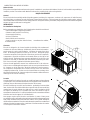
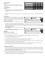
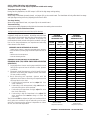
Clearance
The unit is designed to be located outside the building with unobstructed
condenser air inlet and discharge. Additionally, the unit must be situated to
permit access for service and installation. Condenser air enters from three
sides. Air discharges upward from the top of the unit. Refrigerant gauge
connections are made on the right side of the unit as you face the compressor
compartment. Electrical connections can be made either on the right or left
sides of the unit. The best and most common application is for the unit to be
located 10” from wall (4” minimum) with the connection side facing the wall.
This “close to the wall” application minimizes exposed wiring.
Close to the wall application assures free, unobstructed air to the other two
sides. In more confined application spaces, such as corners provide a minimum
10” clearance on all air inlet sides. Allow 18” minimum for service access to
the compressor compartment and controls. The top of the unit should be
completely unobstructed. If units are to be located under an overhang, there
should be a minimum of 36” clearance and provisions made to deflect the warm
discharge air out from the overhang.
Location
Consider the affect of outdoor fan noise on conditioned space and any adjacent
occupied space. It is recommended that the unit be placed so that condenser air
discharge does not blow toward windows less than 25 feet away.
The unit should be set on a solid, level foundation - preferably a concrete slab at
least 4 inches thick. The slab should be above ground level and surrounded by a
graveled area for good drainage. Any slab used as a unit’s foundation should
not adjoin the building as it is possible that sound and vibration may be
transmitted to the structure. For rooftop installation, steel or treated wood beams
should be used as unit support for load distribution.
Heat pumps require special location consideration in areas of heavy snow
accumulation and/or areas with prolonged continuous subfreezing temperatures.
Heat pump unit bases have holes under the outdoor coil to permit drainage of
defrost water accumulation. The unit must be situated to permit free unobstructed
drainage of the defrost water and ice. A minimum 2" clearance under the outdoor
coil is required in the milder climates.
36"
36"
24"
P
L
E
N
U
M
U
N
I
T
P
L
A
T
F
O
R
M
C
U
R
B
FIGURE 2
36"
36"
10"
UNIT
WALL
36"

5
Outside Slab Installation
1. The unit must be mounted on a solid, level foundation. See
Figure 1.
2. Select a location that will minimize the length of the supply and
return ducts.
3 Select a location where external water drainage cannot collect
around the unit.
4. Consideration should also be given to shade, appearance and noise.
Rooftop Installation
1. Figure 2. Before locating the unit on the roof, make sure that the
strength of the roof and beams is adequate to support the weight
involved. (See specification sheet for weight of units.) This is very
important and the installer’s responsibility.
2. Make proper consideration for the weather–tight integrity of the roof
and proper drainage of condensate.
3. To ensure proper condensate drainage, unit must be installed in a level
position.
4. Consideration should also be given to shade, appearance and noise.
DUCTING
Ducting work should be fabricated by the installing contractor in accordance
with local codes. Industry manuals may be used as a guide when sizing and
designing the duct system- such as NESCA (National Environmental Systems
Contractors Association, 1501 Wilson Blvd., Arlington, Virginia 22209).
The unit should be placed as close as possible to the space to be air-conditioned
allowing clearance dimensions as indicated. Ducts should run as directly as
possible to supply and return outlets. Use of non-flammable weatherproof flexible
connectors on both supply and return connections at the unit to reduce noise
transmission is recommended.
It is preferable to install the unit on the roof of the structure if the registers or
diffusers are located in the wall or ceiling. A slab installation is recommended
when the registers are low on the wall or in the floor.
Connecting the Return and Supply Flexible Duct in Manufactured or
Modular Housing Application
The return and supply fittings are to be attached at the unit to a suitable
square to round duct converter. Your distributor has a factory designed
square to round converter transition. The model #’s of these kits are as
follows: Small Chassis 27.5” SQRPCH101, Medium and Large Chassis 32.5”
and 36” SQRPCH102-103 (See Specification Sheets for Dimension details).
The SQRPCH101 has 14" duct collar on supply and 16" duct collar (equivalent
diameter, opening is oval) on the return. The SQRPCH102-103 has a 14"
duct collar on supply and 18" duct collar (equivalent diameter, opening is
oval) on the return. The collars are to be slipped into the openings, and the
flanges bent around the converter. The square to round converter is attached
to the flanges of the square duct openings. The flexible duct is then clamped
on to the collars. Once the duct is affixed to the unit, seal the collars and flanges with a proper waterproof sealant (See Figure 3).
It is strongly encouraged to use appropriately sized ducts based upon the CFM for your application (unit’s CFM). If duct sizing through
industry manuals or air duct calculators require larger ducts than converter openings, run larger duct size up to unit converter openings
and reduce with a reducer duct fitting or transition right at the unit.
Plenum Application
A suitable plenum or square duct must be constructed. The duct cross-sectional
area should be determined by industry duct sizing manuals or air duct calculators.
On ductwork exposed to outside air conditions of temperature and humidity, use
an insulation with a good K factor, and a vapor barrier. Industry practices should
be followed. Balancing dampers are recommended for each branch duct in the
WARNING
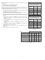
NOMINAL SIZE
(INCHES)
NOMINAL AREA
(SQ. FT.)
10x2
0
1.4
14x2
0
1.9
14x25 2.4
15x2
0
2.1
16x2
0
2.2
16x25 2.8
20x2
0
2.8
20x25 3.5
25x25 4.3
MINIMUM FILTER SIZE
TABLE 1
OUTER FLANGE
STARTER FLANGE
SQUARE TO ROUND
DUCT CONVERTER PANEL
FIGURE 3
500 1000 1500 2000 2500 3000 3500
7
6
5
4
3
2
D
I
S
P
O
S
A
B
L
E
F
I
L
T
E
R
P
E
R
M
A
N
E
N
T
F
I
L
T
E
R
Airflow - SCFM
N
o
m
i
n
a
l
F
i
l
t
e
r
A
r
e
a
S
q
u
a
r
e
F
e
e
t
FIGURE 4
2" Minimum
3" Minimum
A Positive Liquid Seal
Is Required
Flexible
Tubing-Hose
Or Pipe
Drain
Connection
Unit
FIGURE 5

6
supply system. Ductwork should be properly supported from the unit.
NOTE: Proper sealing of all duct work and air handling compartments
is extremely important to overall unit efficiency.
Filters
Filters are not provided with unit, and must be supplied and installed
in the return duct system by the installer. A field installed filter grille is recommended for easy and convenient access to the filters for
periodic inspection and cleaning. Filters must have adequate face area for the rated quantity of the unit. See air delivery tables (Figure
4) for recommended filter size.
PIPING
Condensate Drain
The condensate drain connection of the evaporator is a half coupling of ¾” N.P.T. A trap must be provided to have Proper condensate
drainage.
Install condensate drain trap as shown. Use ¾ “ drain connection
size or larger. Do not operate without trap. Unit must be level or
slightly inclined toward drain.
WIRING
All wiring should be made in accordance with the National
Electrical Code. The local Power Company should be consulted to
determine the availability of sufficient power to operate the unit.
The voltage, frequency, and phase at the power supply should be
checked to make sure it corresponds to the unit’s RATED VOLTAGE
REQUIREMENT.
Install a branch circuit fused disconnect near the unit, in accordance
with the N.E.C. or local codes. Wire sizes and overcurrent protection
should be determined from the unit nameplate ampacity and in
accordance with Table 4 (page 7) or the N.E.C. Under no
circumstances should wiring be sized smaller than is recommended
by either of these two sources.
Fuses smaller than that recommended on the wiring diagrams could
result in unnecessary fuse failure or service calls. The use of protective
devices of larger size than indicated could result in extensive damage
to the equipment. The manufacturer bears no responsibility for damage
caused to equipment as result of the use of larger than is recommended
size protective devices.
All units have undergone a run test prior to packaging for shipment. This equipment has
been started at minimum rated voltage and checked for satisfactory operation. Do not
attempt to operate this unit if the voltage is not within the minimum and maximum
voltages shown on nameplate.
All exterior wiring must be within approved weatherproof conduit. The unit must be
permanently grounded in accordance with local codes, or in absence of local codes,
with N.E.C ANSI/ NFPA NO. 70-1984 or latest edition by using ground lug in the control
box.
Fuses or HACR type circuit breakers may be used where codes permit.
Note: Some single phase units are equipped with a single pole contactor. Caution must
be exercised when servicing as only one leg of the power supply is broken with the contactor.
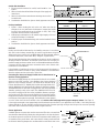
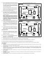
To wire the unit, make the following high and low voltage connections.
CAUTION
CONTACTOR
R
W
G
G
RW
FOR INTERNAL WIRING SEE WIRING LABEL ATTACHED TO UNIT
24 VOLT CONTROL WIRING
FIGURE 6
WARNING
HIGH VOLTAGE!
LEAD THERMOSTAT
Red R (24V)
Green G (Fan)
Yellow Y (Cool)
White W1 (Heat)*
Brown W2 (Heat)*
TABLE 2
TERMINAL THERMOSTAT
Red R (24V)
Green G (Fan)
Orange O (Rev. Valve)
White W1 (Heat, 2nd)*
Brown W2 (Heat 3rd)*
Yellow Y (Cool)
C (Blue) C (Common)
*Optional field installed heat connections
TABLE 3

7
High Voltage Wiring
See Figure 6
Single Phase- Two leads should be connected to terminals L1
& L2 in the electrical control section, using wire sizes specified
in wiring table.
Low Voltage Wiring
See Figure 6
a. Air Conditioners- Connect 24V wires from the thermostat to the
corresponding wires in the control box using No. 18AWG as shown
in Table 2.
b. Heat Pumps- Connect 24V wires from the thermostat to the corresponding wires in the control box using No. 18AWG as shown in
Table 3.
Internal Wiring:
A diagram detailing the internal wiring of this unit is located on the
electrical box cover. If any of the original wire supplied with the
appliance must be replaced, the wire gauge and insulation must be
the same as the original wiring.
Transformer is wired for 230 volts on the 208/230 models. See wiring
diagram for 208 volt wiring.
1. For branch circuit wiring (main power supply to unit disconnect),
the minimum wire size for the length of the run can be determined from Table 4 using the circuit ampacity found on the unit rating
plate. From the unit disconnect to unit, the smallest wire size allowable in Table 4 may be used for the ampacity, as the Disconnect
must be in sight of the unit.
2. Wire size based on 60° C rated wire insulation and 30° C Ambient
Temperature (86° F).
3. For more than 3 conductors in a raceway or cable, see the N.E.C.
for derating the ampacity of each conductor.
OPERATION
Start-Up Procedure and Checklist
Begin with power turned off at all disconnects.
1. Turn thermostat system switch to “Cool,” and fan switch to “Auto” and turn temperature setting as high as it will go.
2. Inspect all registers and set them to the normal open position.
3. Turn on the electrical supply at the disconnect.
4. Turn the fan switch to the “ON” position. The blower should operate after a 10 second delay.
5. Turn the fan switch to “Auto” position. The blower should stop after a 60 second delay.
6. Slowly lower the cooling temperature until the unit starts. The compressor, blower and fan should now be operating. Allow the unit
to run 10 minutes, make sure cool air is being supplied by the unit.
7. Turn the temperature setting to the highest position, stopping the unit. The indoor blower will continue to run for 60 seconds.
8. Turn the thermostat system switch to “OFF” and disconnect all power when servicing the unit.
Heat Pump Start-Up Procedure
9. Check the cooling mode for the heat pump in the same manner as above. The reversing valve is energized when the thermostat is
placed in the cooling position. A clicking sound should be noticeable from the reversing valve. By lowering the temperature setting
to call for cooling, the contractor is energized. The compressor, blower and fan should then be running. After the cooling mode is
checked out, turn the thermostat system switch to “OFF”.
10. Turn the thermostat system switch to “HEAT” and fan switch to “AUTO”.
11. Slowly raise the heating temperature setting. When the heating first stage makes contact, stop raising the temperature setting. The
compressor, blower and fan should now be running with the reversing valve in the de-energized (heating) position. After giving the
unit time to settle out, make sure the unit is supplying heated air.
BRANCH CIRCUIT AMPACITY 15 20 25 30 35 40 45 50
SUPPLY WIRE LENGTH - FEET
200 64443322
150 86644433
100 108866644
50 14 12 10 10 8 8 6 6
TABLE 4
WARNING
HIGH
VOLTAGE
!
D
ISCONNECT
ALL
POWER BEFORE SERVICING OR INSTALLING
THIS UNIT.
M
ULTIPLE POWER SOURCES MAY BE PRESENT. FAILU
TO DO SO MAY CAUSE PROPERTY DAMAGE, PERSONAL INJURY O
DEATH.
RE
R
WARNING
HIGH
VOLTAGE
!
D
ISCONNECT
ALL
POWER BEFORE SERVICING OR INSTALLING
THIS UNIT.
M
ULTIPLE POWER SOURCES MAY BE PRESENT. FAILU
TO DO SO MAY CAUSE PROPERTY DAMAGE, PERSONAL INJURY O
DEATH.
RE
R

8
12. If the out door ambient is above 80°F, the unit may
trip on its high pressure cut out when on heating.
The compressor should stop. The heating cycle
must be thoroughly checked, so postpone the test
to another day when conditions are more suitable
but-DO NOT FAIL TO TEST.
If the out door ambient is low and the unit operates
properly on the heating cycle, you may check the
pressure cutout operation by blocking off the
indoor return air until the unit trips.
13. If unit operates properly in the heating cycle, raise
the temperature setting until the heating second
stage makes contact. Supplemental resistance
heat, if installed should now come on. Make sure
it operates properly.
NOTE: If outdoor thermostats are installed the
outdoor ambient must be below the set point
of these thermostats for the heaters to operate.
It may be necessary to jumper these
thermostats to check heater operation if
outdoor ambient is mild.
14. For thermostats with emergency heat switch, return
to step 11. The emergency heat switch is located
at the bottom of the thermostat. Move the switch
to emergency heat. The heat pump will stop, the
blower will continue to run, all heaters will come
on and the thermostat emergency heat light will
come on.
15. If checking the unit in the wintertime, when the
outdoor coil is cold enough to actuate the
defrost control, observe at least one defrost
cycle to make sure the unit defrosts completely.
Final System Checks
16. Check to see if all supply and return air grilles
are adjusted and the air distribution system is
balanced for the best compromise between
heating and cooling.
17. Check for air leaks in the ductwork.
18. See Sections on Air Flow Measurement and
Adjustment and Checking Charge.
19. Make sure the unit is free of “rattles”, and the tubing in the unit is free from excessive vibration. Also make sure tubes or lines are not
rubbing against each other or sheet metal surfaces or edges. If so, correct the trouble.
20. Set the thermostat at the appropriate setting for cooling and heating or automatic changeover for normal use.
21. Be sure the Owner is instructed on the unit operation, filter, servicing, correct thermostat operation, etc.
The foregoing “Start-up Procedure and Check List” is recommended to serve as an indication that the unit will operate normally.
COMPONENTS
1. Contactor - This control is activated (closed) by the room thermostat for both heating and cooling. The contactor has a 24V coil and
supplies power to the compressor and outdoor fan motor.
2. Crankcase Heater – This item is “ON” whenever power is supplied to the unit and the crankcase heater thermostat is closed.
Crankcase heater thermostat closes at 67° and opens at 85°. It warms the compressor crankcase thereby preventing liquid
migration and subsequent compressor damage. The insert type heater is self regulating. It is connected electrically to the
contactor L1 and L2 terminals.
3. Condenser Motor - This item is activated by the contactor during heating and cooling, except during defrost and emergency
heat operation.
4. Compressor - This item is activated by the contactor for heating and cooling, except during emergency heat. It is protected by
an internal overload.
5. Contactor Relay - This control is activated by the thermostat (24V coil) and supplies power to the contactor.
HEAT PUMP REFRIGERANT CIRCUIT - Figure 7

9
6. Defrost Control - The Defrost control provides time/temperature initiation and termination of the defrost cycle. When a Defrost
cycle is initiated, the defrost control shifts the reversing valve to “cooling” mode, stops the outdoor fan and brings on supplemental
heat. Normally, a Defrost cycle will take only 2-3 minutes unless system is low on charge or outdoor conditions are severe. (Windy
and cold.) The defrost control also provides for a 3 minute off cycle compressor delay.
7. Outdoor Thermostat - These optional controls are used to prevent full electric heater operation at varying outdoor ambient (0° F-to
45° F). They are normally open above their set points and closed below to permit staging of indoor supplement heater operation. If
the outdoor ambient temperature is below 0° F (-18° C) with 50% or higher RH, an outdoor thermostat (OT) must be installed and set
at (0°) on the dial. Failure to comply with this requirement may result in damage to the product which may not be covered by the
manufacturer’s warranty.
8. Reversing Valve Coil - This coil is activated by the thermostat, in the cooling mode and during defrost. It positions the reversing valve
pilot valve for cooling operation.
9. Indoor Blower Motor
Units with EEM Motors Only The EEM model indoor blower motor is activated by the room thermostat by COOLING/HEATING or
FAN ON position. The motor is energized by a 24 volt control signal (from thermostat Y, G or W) for EEM motors. EEM motors are
constant torque motors with very low power consumption.
(See Air Flow Measurement and Adjustment for speed adjustment instructions).
10. Blower Interlock Relay - This relay is used to energize the blower during the electric heat operation. Some room thermostats do not
energize the motor during electric heat. This relay insures blower operation when the room thermostat energizes heat. This relay has
a 240 volt coil and an 8 amp contact relay. This relay is energized by the electric heat kit sequencer.
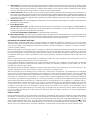
EXPLANATION AND GUIDANCE (HEAT PUMP)
The heat pump is a relatively simple device. It operates exactly as a Summer Air Conditioner unit when it is on the cooling cycle.
Therefore, all the charts and data for service that apply to summer air conditioning apply to the heat pump when it is on the cooling
cycle, and most apply on the heating cycle except that “condenser” becomes “evaporator”, “evaporator” becomes “condenser”,
“cooling” becomes “heating”.
When the heat pump is on the heating cycle, it is necessary to redirect the refrigerant flow through the refrigerant circuit external
to the compressor. This is accomplished with a reversing valve. Thus, the hot discharge vapor from the compressor is directed to
the indoor coil (evaporator on the cooling cycle) where the heat is removed, and the vapor condenses to liquid. It then goes through
the expansion device to the outdoor coil (condenser on the cooling cycle) where the liquid is evaporated, and the vapor goes to the
compressor.
When the solenoid valve coil is operated either from heating to cooling or vice versa, the piston in the reversing valve to the low
pressure (high pressure) reverse positions in the reversing valve.
Figure 7 shows a schematic of a heat pump on the cooling cycle and the heating cycle. In addition to a reversing valve, a heat pump
is equipped with an expansion device and check valve for the indoor coil, and similar equipment for the outdoor coil. It is also
provided with a defrost control system.
The expansion devices are flowrator distributors and perform the same function on the heating cycle as on the cooling cycle. The
flowrator distributors also act as check valves to allow for the reverse of refrigerant flow.
When the heat pump is on the heating cycle, the outdoor coil is functioning as an evaporator. The temperature of the refrigerant
in the outdoor coil must be below the temperature of the outdoor air in order to extract heat from the air. Thus, the greater the
difference in the outdoor temperature and the outdoor coil temperature, the greater the heating capacity of the heat pump. This
phenomenon is a characteristic of a heat pump. It is a good practice to provide supplementary heat for all heat pump installations
in areas where the temperature drops below 45° F. It is also a good practice to provide sufficient supplementary heat to handle the
entire heating requirement should there be a component failure of the heat pump, such as a compressor, or refrigerant leak, etc.
Since the temperature of the liquid refrigerant in the outdoor coil on the heating cycle is generally below freezing point, frost forms
on the surfaces of the outdoor coil under certain weather conditions of temperature and relative humidity. Therefore, it is
necessary to reverse the flow of the refrigerant to provide hot gas in the outdoor coil to melt the frost accumulation. This is
accomplished by reversing the heat pump to the cooling cycle. At the same time, the outdoor fan stops to hasten the temperature
rise of the outdoor coil and lessen the time required for defrosting. The indoor blower continues to run and the supplementary
heaters are energized.
DEFROST CONTROL
During operation the power to the circuit board is controlled by a temperature sensor, which is clamped to a feeder tube entering
the outdoor coil. Defrost timing periods of 30, 60 and 90 minutes may be selected by setting the circuit board jumper to 30, 60 and
90 respectively. Accumulation of time for the timing period selected starts when the sensor closes (approximately 34
+ 5° F), and
when the wall thermostat calls for heat. At the end of the timing period, the unit’s defrost cycle will be initiated provided the sensor
remains closed. When the sensor opens (approximately 60° F), the defrost cycle is terminated and the timing period is reset. If the
defrost cycle is not terminated due to the sensor temperature, a twelve minute override interrupts the unit’s defrost period.

10
SUGGESTED FIELD TESTING/TROUBLE SHOOTING
1. Run unit in the heating mode (room thermostat calling for heat).
2. Check unit for proper charge. Note: Bands of frost on the condenser coil indicate low refrigerant charge.
3. Shut off power to unit.
4. Disconnect outdoor fan by removing the outdoor fan motor wire from “DF2” on defrost control.
5. Restart unit and allow frost to accumulate.
6. After a few minutes of operation, the unit’s defrost thermostat should close. To verify this, check for 24 volts between “DFT” and “C”
on board. If the temperature at the thermostat is less than 28° F and the thermostat is open, replace the unit’s defrost thermostat, as
it is defective.
7. When the unit’s defrost thermostat has closed, short the test pins on the defrost board until the reversing valve shifts, indicating
defrost. This should take up to 22 seconds depending on what timing period the control is set on. After defrost initiation, the short
must instantly be removed or the unit’s defrost period will only last 3 seconds.
8. The control is shipped from the factory with the compressor delay option selected. This will de-energize the compressor contactor for
30 seconds on defrost initiation and defrost termination. If the jumper is set to Normal, the compressor will continue to run during
defrost initiation and defrost termination. The control will also ignore the low pressure switch connected to R-PS1 and PS2 for 5
minutes upon defrost initiation and 5 minutes after defrost termination.
9. After the unit’s defrost thermostat has terminated, check the defrost thermostat for 24 volts between “DFT” and “C”. The reading
should indicate 0 volts (open sensor).
10. Shut off power to unit.
11. Replace outdoor fan motor lead to terminal “DF2” on defrost board and turn on power.
AIR FLOW MEASUREMENT AND ADJUSTMENT
After reviewing section on DUCTING, proceed with airflow measurements and adjustments. Unit’s blower curves (in Specification
Sheets) are based on external static pressure (ESP, in. of W.C.). The duct openings on the unit are considered internal static pressure,
so as long as ESP is maintained, the unit will deliver the proper air up to the maximum static pressure listed for the CFM required by
the application (i.e. home, building, etc.).
In general 400 CFM per ton of cooling capacity is a rule of thumb. Some applications depending on the sensible and latent capacity
requirements may need only 350 CFM or up to 425 CFM per ton. Check condition space load requirements (from load calculations)
and equipment expanded ratings data to match CFM and capacity.
After unit is set and ducted, verify ESP with a 1" inclined manometer with pitot tubes or a Magnahelic gauge and confirm CFM to
blower curves in the specification sheets. All units have multiple speed blower motors. If factory selected speed is not utilized, the
speed tap can be changed. Never run CFM below 350 CFM per ton, evaporator freezing or poor unit performance is possible.
ECM Motor
The ECM control board is factory set with the dip switch #4 in the “ON” position for single stage units and to the "OFF" position for
the 2 stage units. All other dip switches are factory set in the “OFF” position. For most applications, the settings are to be changed
according to the electric heat size.
The ECM motor provides many features not available on the traditional PSC motor. These features include:
• Improved Efficiency
• Constant CFM
• Soft Start and Stop
• Improved Humidity Control
ECM Motor Speed Adjustment
Each ECM blower motor has been preprogrammed for operation at 4 distinct air flow levels when operating in Cooling/Heat Pump
mode or Electric Heat mode. These 4 distinct levels may also be adjusted slightly lower or higher if desired. The adjustment between
levels and the trim adjustments are made by changing the dip switch(s)
either to an "OFF" or "ON" position.
See Blower Performance Data tables in rear of manual.
Dip Switch Functions
The ECM motor has an electronic control that contains eight (8) 2-posi-
tion dip switches. The function of these dip switches is shown in Table
5.
For APC15 / APH16 [24-36] models, dip switch 4 must be set to ON. Dip
switch 4 must be set to OFF for two-stage compressor models APC15 /
APH16 [42-60]. Dip switch 4 ON energizes Y1 signal to the ECM motor
anytime Y/Y2 is energized. The indoor motor will not operate properly if
switch is not set correctly for the model.
DIP SWITCH NUMBER FUNCTION
1
2
3N/A
4Indoor Thermostat
5
6
7
8
Cooling & Heat Pump CFM
CFM Trim Adjust
Electric Heat
TABLE 5

11
APC15 / APH16 CFM Delivery and Adjustments
See pages 14 and 15 for CFM Output, Adjustments and DIP switch settings.
Thermostat “Fan Only” Mode
During Fan Only Operations, the CFM output is 50% of the high stage cooling setting.
Humidity Control
When using a Humidistat (normally closed), cut jumper PJ6 on the control board. The Humidistat will only affect both low stage
and high stage cooling air flow by adjusting the Air flow to 85%.
Two-Stage Heating
When using staged electric heat, cut jumper PJ4 on the control board.
Thermostat Wiring
Use thermostat wiring diagrams provided with the thermostat when making these connections.
See page 14 for Blower Performance Tables.
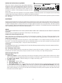
Refrigerant Charge Check (Units with Fixed Orifice Devices)
After completing airflow measurements and adjustments the unit’s
refrigerant charge must be checked. All package units with fixed
orifice devices are charged using the super heat method at the
compressor suction line. After superheat is adjusted it is
recommended to check unit sub-cooling at the condenser coil liquid
line out. For charge adjustments, see superheat and subcooling
charts shown for each model.
SUPERHEAT CAN BE DETERMINED AS FOLLOWS:
1. Read suction pressure. Determine Saturated Suction Tempera-
ture from tables or pressure gauge saturated temperature scale (R-
410A).
2. Read suction line temperature.
3. Use the following formula:
SUPERHEAT = SUCTION LINE TEMP - SAT. SUCTION TEMP.
EXPANSION VALVE (TXV) SYSTEM SINGLE SPEED APPLICATION
(APH1624-36 )
1. Purge gauge lines. Connect service gauge manifold to access
fittings. Run system at least 10 minutes to allow pressure
to stabilize.
2. Temporarily install thermometer on liquid (small) line near
liquid line access fitting with adequate contact and insulate
for best possible reading.
3. Check subcooling and superheat. Systems with TXV
application should have a subcooling and superheat within
the range listed on the chart.
a. If subcooling and superheat are low, adjust TXV then
check subcooling.
b. If subcooling is low and superheat is high, add charge to
raise subcooling then check superheat.
c. If subcooling and superheat are high, adjust TXV valve
then check subcooling.
d. If subcooling is high and superheat is low, adjust TXV
valve superheat and remove charge to lower the
subcooling.
The TXV should NOT be adjusted at light load conditions 55º to
60ºF, under such conditions only the subcooling can be evalu-
ated. This is because suction pressure is dependent on indoor
air flow, and wet bulb temperature.
SUCTION
PRESSURE
SATURATED
SUCTION
TEMPERATURE
ºF
LIQUID
PRESSURE
SATURATED
LIQUID
TEMPERATURE
ºF
PSIG R-410A PSIG R-410A
50 1 200 70
52 3 210 73
54 4 220 76
56 6 225 78
58 7 235 80
60 8 245 83
62 10 255 85
64 11 265 88
66 13 275 90
68 14 285 92
70 15 295 95
72 16 305 97
74 17 325 101
76 19 355 108
78 20 375 112
80 21 405 118
85 24 415 119
90 26 425 121
95 29 435 123
100 31 445 125
110 36 475 130
120 41 500 134
130 45 525 138
140 49 550 142
150 53 575 145
160 56 600 149
170 60 625 152
SATURATED
SUCTION PRESSURE
TEMPERATURE CHART
SATURATED
LIQUID PRESSURE
TEMPERATURE CHART
TABLE 6
Suction Pressure
Temperature (R-410A)
Liquid Pressure
Temperature (R-410A)
SUPERHEAT = SUCTION LINE TEMP - SAT. SUCTION TEMP.

12
NOTE: Do NOT adjust charge based on suction pressure unless there is a gross
undercharge.
4. Disconnect manifold set. Installation is complete.
Two Speed Application
(APC1560/APH1642-60)
Run the unit on low stage cooling for 10 minutes until refrigerant pressures stabilize. Follow
the guidelines and methods below to check unit operation and ensure that the refrigerant
charge is within limits. Charge the unit on low stage.
1. Purge gauge lines. Connect service gauge manifold to access fittings. Run system at
least 10 minutes to allow pressure to stabilize.
2. Temporarily install thermometer on liquid (small) line near liquid line access fitting
with adequate contact and insulate for best possible reading.
3. Check subcooling and superheat. Two stage systems running on low stage with TXV
application should have a subcooling and superheat within the range listed on
the chart.
a. If subcooling and superheat are low, adjust TXV superheat, then check subcooling.
NOTE: To adjust superheat, turn the valve stem clockwise to increase and counter
clockwise to decrease.
b. If subcooling is low and superheat is high, add charge to raise subcooling then
check superheat.
c. If subcooling and superheat are high, adjust TXV valve superheat, then check
subcooling.
d. If subcooling is high and superheat is low, adjust TXV valve superheat and
remove charge to lower the subcooling.
NOTE: Do NOT adjust the charge based on suction pressure unless there is a gross
undercharge.
4. Disconnect manifold set, installation is complete.
Model 5 8 10 15 20
APC1524/APH1624H41** X X X
-- --
APC1530/APH1630H41** X X X X
--
APC1536/APH1636H41** X X X X
--
APC1542/APH1642H41** X X X X
--
APC1548/APH1648H41** X X X X X
APC1560/APH1660H41** X X X X X
Electric Heat kW
TABLE 8
Model #
Superheat
± 2°F
Subcooling
± 2°F
APC1524H41
6
°
---
APC1530H41
8°
---
APC1536H41
12°
---
APC1542H41
7°
---
APC1548H41
10°
---
APC1560H41
12° 12°
APC15H
Design superheat @ 95 °F
outdoor ambient temperature
TABLES 7A & 7B
Model #
Superheat
± 2°F
Subcooling
± 2°F
APH1624H41
15° 7°
APH1630H41
15° 7°
APH1636H41
10° 13°
APH1642H41
12° 13°
APH1648H41
15° 15°
APH1660H41 12° 12°
APH16H
Design superheat @ 95 °F
outdoor ambient temperature

13
ELECTRIC HEAT INSTALLATION & ADJUSTMENT
This series of electric cooling and heat pump package equipment is
designed to accept a field installed electric heat kit. The unit is
equipped to easily install the HKR/HKP Series Electric Heat Kit. Full
Installation Instructions are included in this kit. Please use this
document for guidance in field equipping the package unit with
electric heat.
Choose the heat kit that fits the application for the specific installation. Permanently mark the unit’s nameplate with the model being
installed. High and low voltage connections are detailed in the heat kit instructions.
Indoor Blower motor speed tap selection may need to be modified to accommodate normal continuous operation to prevent a nuisance
trip. See Table 8.
MAINTENANCE
The Self Contained Package Air Conditioner and Heat Pump should operate for many years without excessive service calls if the unit is
installed properly. However it is recommended that the homeowner inspect the unit before a seasonal start up. The coils should be free
of debris so adequate airflow is achieved. The return and supply registers should be free of any obstructions. The filters should be
cleaned or replaced. These few steps will help to keep the product up time to a maximum. The Troubleshooting Chart (on page 16) should
help in identifying problems if the unit does not operate properly.
SERVICE
THE FOLLOWING INFORMATION IS FOR USE BY QUALIFIED SERVICE AGENCY ONLY: OTHERS SHOULD NOT ATTEMPT TO SERVICE THIS
EQUIPMENT.
Common Causes of Unsatisfactory Operation of Heat Pump on the Heating Cycle.
Inadequate Air Volume Through Indoor Coil
When a heat pump is in the heating cycle, the indoor coil is functioning as a condenser. The return air filter must always be clean,
and sufficient air volume must pass through the indoor coil to prevent excessive discharge pressure, and high pressure cut out.
Outside Air Into Return Duct
Do not introduce cold outside air into the return duct of a heat pump installation. Do not allow air entering the indoor coil to drop
below 65° F. Air below this temperature will cause low discharge pressure, thus low suction pressure, and excessive defrost
cycling resulting in low heating output. It may also cause false defrosting.
Undercharge
An undercharged heat pump on the heating cycle will cause low discharge pressure resulting in low suction pressure and frost
accumulation on the outdoor coil.
Poor “Terminating” Sensor Contact
The unit’s defrost terminating sensor must make good thermal contact with the outdoor coil tubing. Poor contact may not
terminate the unit’s defrost cycle quickly enough to prevent the unit from cutting out on high discharge pressure.
Malfunctioning Reversing Valve
This may be due to:
1. Solenoid not energized - In order to determine if the solenoid is energized, touch the nut that holds the solenoid cover in place
with a screwdriver. If the nut magnetically holds the screwdriver, the solenoid is energized and the unit is in the cooling cycle.
2. No voltage at unit’s solenoid - Check unit voltage. If no voltage, check wiring circuit.
3. Valve will not shift:
a. Undercharged - check for leaks;
b. Valve Body Damaged - Replace valve;
c. Unit Properly Charged - If it is on the heating cycle, raise the discharge pressure by restricting airflow through the indoor
coil. If the valve does not shift, tap it lightly on both ends with a screwdriver handle. Do Not Tap The Valve Body. If the unit is
on the cooling cycle, raise the discharge pressure by restricting airflow through the outdoor coil. If the valve does not shift
after the above attempts, cut the unit off and wait until the discharge and suction pressure equalize, and repeat above steps.
If the valve does not shift, replace it.
WARNING
HIGH VOLTAGE!

14
** Denotes factory settings for APC1560H41
*** Denotes factory setting for APH1660H41
ADJUSTING SPEED TAP FOR INDOOR BLOWER MOTOR
Cooling/HP
Speed
Adjust
Tap
CFM*
Electric
Heat
Adjust
Tap
CFM*
Cooling/HP
Speed
Adjust
Tap
CFM*
Electric
Heat
Adjust
Tap
CFM*
D Minus 858 D Minus 858 D Minus 969 D Minus 969
D Normal 953 D Normal 953 D Normal 1,073 D Normal 1,073
D Plus1,048 D Plus1,048 D Plus1,180 D Plus1,180
C Minus 800 C Minus 800 C Minus 930 C Minus 930
C Normal 905 C Normal 905 C Normal 1,032 C Normal 1,032
C Plus 986 C Plus 986 C Plus 1,135 C Plus 1,135
B Minus 743 B Minus 743 B Minus 834 B Minus 834
B Normal 847 B Normal 847 B Normal 984 B Normal 984
B Plus 939 B Plus 939 B Plus 1,101 B Plus 1,101
A Minus 714 A Minus 714 A Minus 833 A Minus 833
A Normal 815 A Normal 815 A Normal 937 A Normal 937
A Plus 903 A Plus 903 A Plus 1,036 A Plus 1,036
* @ 0.1 - 0.9 ESP * @ 0.1 - 0.9 ESP
Cooling/HP
Speed
Adjust
Tap
CFM*
Electric
Heat
Adjust
Tap
CFM*
Cooling/HP
Speed
Adjust
Tap
CFM*
Electric
Heat
Adjust
Tap
CFM*
D Minus 1,135 D Minus 1,135 D Minus 1,289 D Minus 1,289
D Normal1,270 D Normal1,270 D Normal1,392 D Normal1,392
D Plus1,371 D Plus1,371 D Plus1,440 D Plus1,440
C Minus 1,042 C Minus 1,042 C Minus 1,219 C Minus 1,219
C Normal1,178 C Normal1,178 C Normal1,323 C Normal1,323
C Plus1,307 C Plus1,307 C Plus1,419 C Plus1,419
B Minus 932 B Minus 932 B Minus 1,182 B Minus 1,182
B Normal1,065 B Normal1,065 B Normal1,294 B Normal1,294
B Plus1,181 B Plus1,181 B Plus1,384 B Plus1,384
A Minus 823 A Minus 823 A Minus 1,105 A Minus 1,105
A Normal 952 A Normal 952 A Normal 1,219 A Normal 1,219
A Plus1,080 A Plus1,080 A Plus1,304 A Plus1,304
* @ 0.1 - 0.9 ESP * @ 0.1 - 0.9 ESP
Cooling/HP
Speed
Adjust
Tap
CFM*
Electric
Heat
Adjust
Tap
CFM*
D Minus 1,506 D Minus 1,506
DNormal**
*
1,699 D Normal 1,699
D Plus1,872 D Plus1,872
C Minus 1,420 C Minus 1,420
C Normal 1,596 C Normal 1,596
C Plus1,764 C Plus1,764
B Minus 1,323 B Minus 1,323
B Normal 1,491 B Normal 1,491
B Plus** 1,642 B Plus** 1,642
A Minus 1,217 A Minus 1,217
A Normal 1,385 A Normal 1,385
A Plus1,537 A Plus1,537
* @ 0.1 - 0.9 ESP
APH1636H41 / APC1536H41 APH1642H41 / APC1542H41
APH16[48-60]H41 / APC15[48-60]H41
Evaporator Blower Specifications with ECM Motors
APH1624H41 / APC1524H41 APH1630H41 / APC1530H41

15
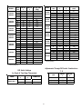
Adjustments Through DIP Switch Combinations
7 - 8
DIP Switch Settings
for Single & Two-Stage Thermostats
MODEL
SWITCH
3
SWITCH
4
THERMOSTAT
N/A ON Single Stage
N/A OFF Two-Stage
APC15/H16**
CFM
SWITCH
7
SWITCH
8
Plus10% ON OFF
Normal OFF OFF
Minus10% OFF ON
MODEL
SPEED
TAP
SWITCH
1
SWITCH
2
ELECTRIC HEAT
(CFM)
A Off Off
815
(F)
B On Off 847
C Off On 905
D On On 953
A Off Off
937
(F)
B On Off 984
C Off On 1032
D On On 1,073
A Off Off
952
(F)
B On Off 1065
C Off On 1178
D On On 1270
A Off Off 1219
B On Off 1294
C Off On
1323
(F)
D On On 1392
A Off Off
1385
(F)
B On Off 1491
C Off On 1596
D On On 1699
A Off Off 1385
B On Off
1491
(F)
C Off On 1596
D On On 1699
A Off Off 1385
B On Off 1491
C Off On 1596
D On On
1699
[F]
(F)
Factory Setting
APC1524
APH1624
APC1530
APH1630
APC1536
APH1636
APH1660
APC1542
APH1642
APC1548
APH1648
APC1560
MODEL
SPEED
TAP
SWITCH
5
SWITCH
6
COOLING/ HP
(CFM)
A Off Off
815
(F)
B On Off 847
C Off On 905
D On On 953
A Off Off
937
(F)
B On Off 984
C Off On 1032
D On On 1,073
A Off Off
952
(F)
B On Off 1065
C Off On 1178
D On On 1270
A Off Off 1219
B On Off 1294
C Off On
1323
(F)
D On On 1392
A Off Off
1385
(F)
B On Off 1491
C Off On 1596
D On On 1699
A Off Off 1385
B On Off
1491
(F)
C Off On 1596
D On On 1699
A Off Off 1385
B On Off 1491
C Off On 1596
D On On
1699
[F]
(F)
Factory Setting
APC1524
APH1624
APC1530
APH1630
APC1536
APH1636
APH1660
APC1542
APH1642
APC1548
APH1648
APC1560

16
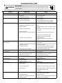
TROUBLESHOOTING CHART
WARNING
HIGH VOLTAGE!
D
ISCONNECT
ALL
POWER
BEFORE
SERVICING
OR
INSTALLING
THIS
UNIT
. M
ULTIPLE
POWER
SOURCES
MAY
BE
PRESENT
. F
AILURE
TO
DO
SO
MAY
CAUSE
PROPERTY
DAMAGE
,
PERSONAL
INJURY
OR
DEATH
.
SYMPTOM
High head - low suction a. Restriction in liquid line or flowrator a. Remove or replace with proper size flowrator.
High head - high or normal suction a. Dirty condenser coil a. Clean coil
b. Overchar
g
ed b. Correct S
y
stem char
g
e
c. Condenser fan not running c. Repair or Replace
a. Incorrect flowrator a. Replace with correct flowrator
b. Defective compressor valves b. Replace compressor
c. Flowrator not seating properly c. Check for debris under flowrator or deformed
flowrator. Remove debris or replace flowrator.
a. Power off or loose electrical connection a. Check for unit voltage at contactor in unit
b. Thermostat out of calibration set too hi
g
h b. Reset
c. Defective contactor c. Check for 24 volts at contactor coil replace if contacts
are open
d. Blown fuses or tripped breaker d. Replace fuse or reset breaker Check wiring - replace
transformer
e. Transformer defective
f. High or low pressure control open (Optional) f. Reset high pressure control or check unit charge
High pressure control opens at 610 psig
Low pressure control opens at 22 psig
g. Compressor overload contacts open g. Replace compressor
NOTE: Wait at least 2 hours for overload to
reset
Condenser fan runs,
compressor doesn't
a. Loose connection a. Check for unit voltage at compressor check & tighten
all connections
b. Compressor stuck, grounded or open winding
open internal overload
b. Wait at least 2 hours for overload to reset If still open,
replace the compressor.
c. Low voltage connection c. At compressor terminals, voltage must be within
10 % of na meplate volts when unit is operating
d. Capacitor weak, open, or shorted d. Check capacitor. If defective, replace.
Low suction - cool compressor a. a.
Iced evaporator coil
a. Defective overload protector a. Replace - check for correct voltage
b. Unit cycling on low pressure control b. Check refrigerant charge and / or airflow
c. High pressure switch cuts out c. Check airflow (Indoor & outdoor)
a. a. Increase speed of blower or reduce restriction
replace air filters
a. Excessive load a. Recheck load calculation
b. Defective compressor b. Replace
c. Reversing valve not seating properly. c. Replace
a. Improperly sized unit a. Recalculate load
b. Improper airflow b. Check - should be approximately 400 CFM per ton
c. Incorrect refrigerant charge. c. Charge per procedure attached to unit service panel
d. Incorrect voltage d. At compressor terminals, voltage must be within 10%
of nameplate volts when unit is
operating
Evaporator coil freezing or frosting a. Low airflow a. Check - should be approximately 400 CFM per ton,
dirty air filters, all duct outlets open
b. Low refrigerant charge b. Properly charge unit
c. Operating unit in cooling mode below 65°F
outdoor temperature
c. Install or check low ambient control, should be open
below 65°F outdoor temperature
REMEDYPOSSIBLE CAUSE
Compressor short cycles
Registers sweat Low airflow
Low head - high suction
Unit will not run
Low indoor airflow Increase speed of blower or reduce restriction -
replace air filters
Insufficient cooling
High suction pressure

17
PACKAGE UNITS - HEAT PUMP AND AC UNITS
HOMEOWNER’S ROUTINE MAINTENANCE RECOMMENDATIONS
coil with water. This cleaning practice remains as the recom-
mended cleaning method for both copper tube and aluminum
tube residential cooling coils.
An alternate cleaning method is to use one of the products listed
in the technical publication TP-109 (shipped in the literature
bag with the unit) to clean the coils. The cleaners listed are the
only agents deemed safe and approved for use to clean round
tube aluminum coils. TP-109 is available on the web site in
Partner Link > Service Toolkit.
NOTE: Ensure coils are rinsed well after use of any chemical clean-
ers.
A
NNUAL INSPECTION (QUALIFIED SERVICER ONLY)
Your package unit should be inspected by a qualified installer,
or service agency at least twice every year. This check should be
performed before the heating and cooling seasons begin. This
will ensure that the system is performing properly and safely.
Repair as necessary.
• Check physical support of the unit. Ensure it is sound
without any sagging, cracks, or gaps, around the base.
• Check for obvious signs of deterioration of the unit.
• Check both condenser and evaporator coil to make sure
each are clean.
•
Return Air Connection. Check for physical soundness and
ensure that the connection is firmly sealed to the package
unit casing.
•
Wiring. Check wires for damage. Check electrical
connections for tightness and/or corrosion.
•
Filters. Check that filters are clean and in the proper
placement in the unit or duct system.
•
Louvers. Inspect air inlet louvers inside the heat exchanger
compartments. Ensure the area is clean and free of dirt and
debris.
BEFORE CALLING YOUR SERVICER
• Check the thermostat to confirm that it is properly set.
•
Check the disconnect switch near the unit to confirm that it
is closed.
•
Check the electrical panel for tripped circuit breakers or
failed fuses . Reset the circuit breakers or replace fuses as
necessary.
• Check for blockage of the indoor air inlets and outlets.
Confirm that they are open and have not been blocked by
objects (rugs, curtains or furniture).
•
Check for obstructions on the unit . Confirm that it has not
been covered on the sides or the top. Remove any obstruction
that can be safely removed. If the unit is covered with dirt or
debris, call a qualified servicer to clean it.
•
Check the filter. If it is dirty, clean or replace it.
We strongly recommend a bi-annual maintenance checkup be performed by a qualified service agency before the heating and cooling seasons begin.
REPLACE OR CLEAN FILTER
IMPORTANT NOTE: Never operate unit without a filter installed
as dust and lint will build up on internal parts resulting in loss
of efficiency, equipment damage and possible fire.
A return air filter is not supplied with this unit; however, there
must be a means of filtering the return air. An indoor air filter
must be used with your comfort system. A properly maintained
filter will keep the indoor coil of your comfort system clean. A
dirty coil could cause poor operation and/or severe equipment
damage.
The installer of your unit can tell you where your filter(s) are
and how to clean or replace them.
Check your return filter(s) at least once every two months.
When they are dirty, replace or clean as required. Disposable
type filters should be replaced. Reusable type filters may be
cleaned.
NOTE: Reusable type filters should be washed with warm
water, dried completely and sprayed with an adhesive
according to the manufacturers recommendations.
You may want to ask your dealer about high efficiency filters.
High efficiency filters are available in both electronic and non-
electronic types. These filters can do a better job of catching
small airborne particles.
Improper filter maintenance is the most common cause of inad-
equate heating or cooling performance. Filters should be cleaned
(permanent) or replaced (disposable) every two months or as
required. When replacing a filter, it must be replaced with a
filter of the same type and size and always make certain the air
flow arrows on the filter point in the proper direction.
CONDENSER AND EVAPORATOR MOTORS
The bearings on the air circulating blower motor and condenser
motor are permanently lubricated and require no further lubri-
cation.
COMPRESSOR
The compressor motor is hermetically sealed and does not re-
quire additional oiling.
ALUMINUM INDOOR COIL CLEANING (QUALIFIED SERVICER ONLY)
This unit is equipped with an aluminum tube evaporator coil.
The safest way to clean the evaporator coil is to simply flush the

18
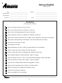
Start-up Checklist
*Store in job file
Pre Start-Up
(Check each item as completed)
Verify all packaging material has been removed.
Remove all shipping brackets per installation instructions.
Verify the job site voltage agrees with the unit serial plate.
Verify condensate connection is installed per installation instructions.
Verify proper clearance around the unit for safety, service, maintenance and proper unit operation.
Verify proper weatherproofing of all ductwork, roof curbs and electrical connections.
Check that the flue screen is in place.
Check gas piping for leaks.
Verify gas pressure to the unit is within the range specified on the serial plate.
Check to ensure that all fans, pulleys and wheels are secure.
Check for proper belt tension and alignment per installation instructions.
Check refrigerant piping for rubbing and leaks. Repair if necessary.
Check unit wiring to ensure it is not in contact with refrigerant piping or sharp metal edges.
Check all electrical connections and terminals. Tighten as needed.
Verify that the crankcase heaters have been energized for 24 hours.
Verify the scroll compressor(s) are rotating in the right direction.
Verify all accessories are installed and operating correctly.
Check filters and replace if necessary.
Verify the installation of the thermostat.
9/2014
Date: ___________________________________
Model Number: ___________________________________
Serial Number: ___________________________________
Technician: ___________________________________
Location: __________________________________________
__________________________________________
__________________________________________
Unit #: __________________________________________
is a registered trademark of Maytag Corporation or its related companies and is used under license to Goodman Company, L.P., Houston, TX, USA. All rights reserved.

19
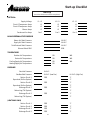
Start-up Checklist
L1 - L2 L2 - L3 L3 - L1
L1 L2 L3
L1 L2 L3
L1 L2 L3
Fan 1Fan 2Fan 3
IN. W.C.
IN. W.C.
IN. W.C.
RPM
DB WB
DB WB
DB WB
DB
IN. W.C.
IN. W.C. (Low Fire) IN. W.C. (High Fire)
PSIG °F
°F
PSIG °F
°F
PSIG °F
°F
PSIG °F
°F
PSIG °F
PSIG °F
PSIG °F
PSIG °F
BLOWER EXTERNAL STATIC PRESSURE
Return Air Static Pressure
Supply Air Static Pressure
Supply Voltage
Circuit 1 Compressor Amps
Circuit 2 Compressor Amps
Blower Amps
Condenser Fan Amps
ELECTRICA
L
Total External Static Pressure
Blower Wheel RPM
TEMPERATURES
Outdoor Air Temperature
Return Air Temperature
Cooling Supply Air Temperature
Discharge Circuit 1
Heating Supply Air Temperature
PRESSURES
Gas Inlet Pressure
Gas Manifold Pressure
Suction Circuit 1
Suction Circuit 2
Discharge Circuit 2
Superheat (Orifice System)
Superheat (Orifice System)
Subcooling (TXV System)
Subcooling (TXV System)
Discharge Circuit 1
Discharge Circuit 2
(HEAT PUMP ONLY)
Suction Circuit 1
Suction Circuit 2
Start-Up
(Insert the values as each item is completed.)

20
Goodman Company, L.P.
5151 San Felipe, Suite 500, Houston, TX 77056
www.amana-hac.com
© 2015-2018• Goodman Company, L.P.
All information contained herein is subject to change without notice.
is a registered trademark of Maytag Corporation or its related companies and is used under license to Goodman Company, L.P., Houston, TX, USA. All rights reserved.
CUSTOMER FEEDBACK
We are very interested in all product comments.
Please fill out the feedback form on one of the following links:
Amana® Brand Products:
(http://www.amana-hac.com/about-us/contact-us).
You can also scan the QR code on the right for the product brand
you purchased to be directed to the feedback page.
PRODUCT REGISTRATION
Thank you for your recent purchase. Though not required to get the protection
of the standard warranty, registering your product is a relatively short process,
and entitles you to additional warranty protection, except that failure by
California and Quebec residents to register their product does not diminish
their warranty rights.
For Product Registration, please register as follows:
Amana® Brand products: (http://www.amana-hac.com/product-registration)
You can also scan the QR code on the right for the product brand
you purchased to be directed to the Product Registration page.
AMANA® BRAND
AMANA® BRAND
-
 1
1
-
 2
2
-
 3
3
-
 4
4
-
 5
5
-
 6
6
-
 7
7
-
 8
8
-
 9
9
-
 10
10
-
 11
11
-
 12
12
-
 13
13
-
 14
14
-
 15
15
-
 16
16
-
 17
17
-
 18
18
-
 19
19
-
 20
20


Maytag APH16 H Series Installation Instructions Manual
- Category
- Split-system air conditioners
- Type
- Installation Instructions Manual
Ask a question and I''ll find the answer in the document
Finding information in a document is now easier with AI
Related papers
-
Broan Q4SE Installation guide
-
Broan P7RF Installation guide
-
Broan GQ4SD-O Installation guide
-
Broan Q6SD-X Installation guide
-
-
Broan PPA2RF Installation guide
-
Broan Q7RD Installation guide
-
-
Broan PPA2RF-A Installation guide
-
Other documents
-
Amana APC14H Owner's manual
-
Intertherm HSA1QE Installation guide
-
 GOODMAN GPH1648H41 Installation guide
-
Reznor WSA2BD-C (3 Phase) Installation guide
-
Lennox (2/4)SH13 User manual
-
Carrier 50ZHB Owner's manual
-
Bryant 214D Owner's manual
-
Amana REMOTE CONDENSING UNIT User manual
-
-
 Thermo Products 14 SEER User manual

