Diamond MICRO4V2 Owner's manual

Category
Car audio amplifiers
Type
Owner's manual

This manual is also suitable for

AMPLIFIERSAMPLIFIERS
MICROV2 SeriesMICROV2 Series
AFE TURES
ABOUT THE DIAMOND AUDIO EXPERIENCE
POWER RATINGS
,
Congratulations, you have just purchased one of the finest mobile audio products on the
market. Diamond Audio products represent the latest advances in acoustic technology in
sound reproduction for your vehicle. Diamond Audio products are designed, developed, and
engineered in the USA using the latest innovative materials and components to provide the
finest sound reproduction possible. Every Diamond Audio product has been verified and
tested to ensure the best sounding and most reliable product on the market, if installed
properly .Diamond Audio products will provide many years of the ultimate listening experience.
Please note that prolonged exposure to sound pressure levels in excess of 100dB can cause
permanent hearing loss. Using Diamond Audio products can exceed that level so please
exercise restraint in its operation in order to preserve your ability to enjoy its high fidelity sound
for many years to come.
Diamond Audio recommends our products be professionally installed by an authorized
Diamond Audio dealer to achieve the best possible system recommendation and installation.
This will ensure a true Diamond Audio listening experience and sound you would expect from
Diamond Audio products. With proper validation, using a Diamond Audio Retialer for installation,
your newly purchased amplifier, Diamond Audio will extend the product warranty from one year
to Two Years!!
Go ahead, Hear the Music





MICRO1V2
500 W RMS
300 W X 1
175 W X 1
500 W X 1
300 W
175 W
MICRO2V2
500 W RMS
250 W X 2
150 W X 2
N/A
N/A
500 W X 1
MICRO4V2
600 W RMS
150 W X 4
80 W X 4
N/A
N/A
300 W X 2
Full Range Class D IR Chipset
DirectFET Power Mosfet Output Stage
SMD Technology on 4 layer Glass PC Board
ICAD circuit provides superior overload protection
Frequency response 20 HZ – 30kHz
Variable 12db crossovers
Bridgeable / 2ch-4ch switch control

MICRO Bass boost +12DB @45Hz
Premium 8 and 4 gauge power connections
Multi channels / Mono channel
MICRO5V2
900 W RMS
150 W X 4/350 W X 1
80 W X 4/200 W X1
N/A
N/A
300 W X 2/200 W X 1
Installation
INSTALLATION -Pre Planning Section
3
WARNING: Prolonged exposure to sound pressure levels in excess of 100dB can cause permanent hearing loss.
DIAMOND AUDIO amplifiers can exceed that level so please exercise restraint when listening to your new amplifier.
GENERAL PRECAUTIONS
• This unit is designed for negative ground 12V DC operation only.
• Total system impedance must Not be less than 2 Ohms stereo, or 1 Ohm bridged for MICRO1V2. MICRO5V2 is
minimum 2 Ohms bridged on sub channel(ch5), and the MICRO4V2. MICRO5V2(ch 1, 2, 3, 4) is 4 ohms
bridged mono (stereo)
• Avoid installing the unit where: It would be subject to high temperatures, such as from direct sunlight or hot air
from the heater. - It would be exposed to rain, moisture, dust or dirt.
• Do not cover the unit with carpet or wires.
• Do not use the unit with a weak auto battery. Optimum performance depends on optimum battery supply
voltage.
• For safety reasons, keep the volume of your car audio system moderate while driving your vehicle so that you
can still hear normal traffic sounds outside your car.
• There is NO speaker level input connector, you can cut RCA's and solder the wires and connect directly thru low
level input(RCA) Or purchase the “optional ” RCA Adaptor cable to make a cleaner connection, model - DAHILVL
MOUNTING PRECAUTIONS
Although DIAMOND AUDIO amplifiers incorporate heat sinks and protection circuits, mounting the amplifier in a
tight space without any air movement can still damage internal circuitry over time. Choose a location that provides
adequate ventilation around the amplifier. For easy system set-up, mount the amplifier so the side panel controls
will be accessible after installation. To increase thermal run times on low impedance loads, an additional fan is
recommended, remember any moving air across the amplifier will reduce heat. In addition, observe the following
precautions:
1. Using a felt pen mark the mounting hole locations.
2. Mounting the amplifier on carpet will significantly reduce air flow, resulting in reduced thermal run times.
3. Mount the amplifier on a solid surface. Avoid mounting to sub woofer enclosures or areas prone to vibration. Do
not install the amplifier on plastic or other combustible materials.
4. Prior to mounting the amplifier, make sure not to cut or drill into the fuel tank, fuel lines, brake lines (under
chassis) or electrical wiring.
WIRING PRECAUTIONS
1. Before installation, make sure the source unit power switch is in the OFF position.
2. Disconnect the negative (-) lead of the battery before making any power connections.
3. When making connections, be sure that each one is clean and secure. Insulate all of your connections. Failure to
do so may damage your equipment.
4. A secure clean ground connection is critical to the performance of your amplifier. Connect the ground directly to
the car chassis to minimize resistance and avoid any noise problems.
5. Add an external fuse on the amplifier's positive (+) power lead and connect it as close as possible to the
vehicle's (+) battery terminal. Use a rating that equals the total current consumption at full output of all
amplifiers in the system. This external fuse will protect the vehicle from short circuits that can cause a fire.
4
FEATURES/FUNCTIONS
12 1
4
5
132
7
3
11
14
11
14
11
14
11
12 1
4
5
237
10
54 5 12 4
10
37
2
8 7
11
14
1111
2 4 2 18 4
257 3 8 712
5
FEATURES/FUNCTIONS











 

























MICRO2V2 - Stereo 2 ohms
w/4 speakers
6
INSTALLATION

Amplifiers (regardless of brand name) will put an increased load on the vehicle's battery and charging system.
DIAMOND AUDIO recommends checking your alternator and battery condition to ensure that the electrical system has
enough capacity to handle the increased load of your stereo system. Original equipment electrical systems, which are in
good condition, should be able to handle the extra load of any DIAMOND AUDIO amplifier without problems, although
battery and alternator life can be reduced depending on your individual listening habits.
WARNING:
Avoid running power wires near the low level input cables, antenna, power leads, sensitive equipment or harnesses. The
power wires carry substantial current and could radiate noise into the audio system through the audio cables.
INSTALLATION:
1. Plan the wire routing. Keep RCA cables close together but isolated from the amplifier's power cables and any high
power auto accessories, especially electric motors. This is done to prevent coupling the noise from radiated electrical
fields into the audio signal. When feeding the wires through the firewall or any metal barrier, protect them with
plastic or rubber grommets to prevent short circuits. Leave the wires long at this point to adjust for a precise fit at a
later time.
2. Prepare the power wire for attachment to the
amplifier by stripping 5/8 inch (15.9mm) of
insulation from the end of the wire. Insert the
bare wire into the B+ terminal And tighten the
set screw to secure the cable in place.
WARNING:
The B+ cable MUST be fused 18" or less from the
vehicle's positive battery post. Choose a location
to install a waterproof fuse holder under the hood
and ensure connections are watertight. If you do
not use the appropriate fuse holder, the
connection will eventually suffer corrosion from
moisture and heat.
3. Trim the power cable within 18 inches
(45.7mm) of the positive battery post and
splice in a in-line fuse holder. DO NOT install the
fuse at this time.
4. Strip 1/2 inch (12.7mm) from the battery
end of the power cable. Crimp and soldier a
large ring terminal to the cable. Connect the
ring terminal to the positive (+) battery post.
7
INSTALLATION
5. Prepare the ground wire for attachment to the amplifier by stripping 5/8" of insulation from the end of the wire. Always
use a wire of the same gauge as the power connection, never smaller. Insert the bare wire into the GND terminal and
tighten the set screw to secure the cable in place. Prepare the chassis ground by scraping any paint from the metal
surface and thoroughly clean the area of all dirt and grease. Strip the other end of the wire, crimp and soldier a ring
connector. Fasten the cable to the chassis using a non-anodized screw with a star washer and a nut.
WARNING: It is important to upgrade the ground connection
between the negative (-) battery post and the vehicle body or
chassis to achieve optimum electrical performance.
6. Prepare the REM turn-on wire for attachment to the amplifier
by stripping 5/8 inch (15.9mm) of insulation from the end
of the wire. Insert the bare wire into the REM terminal and
tighten the set screw to secure the wire in place. Connect the
other end of the REM wire to a switched 12 volt positive
source. The switched voltage is usually taken from the
source unit's remote amp turn on lead. If the source unit
does not have this output available, the recommended
solution is to wire to an accessory terminal in the car's fuse
block using a relay to isolate the amplifier from the vehicles
accessory circuit. This however will turn the amplifier on and
off with the ignition key, regardless of whether the car stereo
is on or off.
7. Securely mount the amplifier to the vehicle or amp rack. Be careful not to mount the amplifier on cardboard or plastic
panels. Doing so may enable the screws to pull out from the panel due to road vibration or sudden vehicle stops.
8. Connect from source signal by connecting the RCA audio cables to the input jacks at the amplifier.
9. Connect the car speakers. Speakers impedance should never be less than 2 Ohms stereo, 4 Ohms bridged(the MICRO1V2
mono block is stable into 1 ohms). For most applications 18 gauge wire is adequate for the speaker leads. For leads in
excess of ten feet, 16 gauge wire is recommended. When wiring the speakers, pay careful attention to the polarity of the
terminals on the speakers and make certain they correspond to the polarity on the amplifier. DO NOT chassis ground any
of the speaker leads as unstable operation or damage to the amplifier and/or speaker may result.




8
SET UP
Placing the x-over switch in the FULL position (MICRO4V2/MICRO5V2) sets the amplifier to Full Range. This setting allows
ALL frequencies to pass to the speakers. With the MICRO4V2/MICRO5V2, Placing the
switch in the HP or LP position activates the 12dB crossover, adjustable from 40Hz -
400Hz. . The MICRO1V2 mono is dedicated for Low Pass (LP) only with an adjustable
frequency from 40Hz - 400Hz. The MICRO5V2 (5 channel) amplifier offers full range
(FULL) or high pass (HP) selector switch for channels 1-4. Selecting the high pass
(HP) will activate a fixed 70Hz cross over for full range speakers. Channel 5 (on
MICRO5V2) is dedicated for subwoofers only but offers an adjustable LP crossover
from 25Hz – 250Hz.
Placing the switch in the HP sets the amplifier to the High Pass Filter mode, enabling frequencies above the cutoff point to
pass. Placing the switch in the LP position sets the amplifier to the Low Pass Filter mode, enabling frequencies below the cutoff
point to pass. For system tuning begin with the frequency set at approximately 80Hz and fine tune up or down based on
music choice and input level.
To adjust the gain setting, turn the amplifier gains all the way down (counterclockwise). If using a remote level control
(MICRO1V2/MICRO5V2), plug the level control into the amplifier and turn it to about "HALF-WAY" (approx. the 12 O'clock
position) this setups the bass boost so you can turn it UP ..OR...turn it DOWN when playing different music styles. Next turn
the source unit volume up to almost full volume (usually about 2/3rds of the way up) or until the output starts to distort on
an oscilloscope. This will be NEARLY full volume on most source units, perhaps one or two "clicks" down from maximum
volume. Next, increase the amplifier gain setting until adequate volume is achieved, or until distortion is audible and then turn
it down a bit until the distortion is inaudible.




The HP or LP crossover adjustment can now be fine tuned. If you are using the amplifier in a HP configuration and would like
the system to be a little bit louder you can increase the HP Filter frequency and reset the "Gain" of the amplifier. Raising the
HP frequency up to high however will cause a loss of mid range and bass. If you are using the amplifier in a HP filter configura-
tion and you hear voice or vocals coming from your subwoofer system you can turn the LP Filter frequency down (lower).
After setting the input gain adjustment and crossover, you may choose to add a small amount of "Bass Boost" (MICRO1V2)
in the low frequency region. Remember that the Bass Boost feature will not fix a poorly designed subwoofer enclosure or
subwoofers that didn't sound good to begin with.
1. Make sure any bass EQ or low frequency equalization from the source unit is set to OFF or FLAT.
2. While playing the same musical selections used during the gain setting process, slowly increase the level of the Bass EQ.
You should be able to notice a obvious change between 0 and +12dB. If you do not notice much difference, then it will
not serve any benefit to increase the boost further. 3. If the boost has audible benefits without adding appreciable
distortion, find a level that suits your taste. Remember: it's much easier to construct the right subwoofer enclosure for
your listening preferences than relying on a bass boost control to do the job!
9
SYSTEM CONFIGURATIONS
Placing the x-over switch in the FULL position (MICRO4V2/MICRO5V2) sets the amplifier to Full Range. This setting allows
ALL frequencies to pass to the speakers. With the MICRO4V2/MICRO5V2, Placing the
switch in the HP or LP position activates the 12dB crossover, adjustable from 40Hz -
400Hz. . The MICRO1V2 mono is dedicated for Low Pass (LP) only with an adjustable
frequency from 40Hz - 400Hz. The MICRO5V2 (5 channel) amplifier offers full range
(FULL) or high pass (HP) selector switch for channels 1-4. Selecting the high pass
(HP) will activate a fixed 70Hz cross over for full range speakers. Channel 5 (on
MICRO5V2) is dedicated for subwoofers only but offers an adjustable LP crossover
from 25Hz – 250Hz.
Placing the switch in the HP sets the amplifier to the High Pass Filter mode, enabling frequencies above the cutoff point to
pass. Placing the switch in the LP position sets the amplifier to the Low Pass Filter mode, enabling frequencies below the cutoff
point to pass. For system tuning begin with the frequency set at approximately 80Hz and fine tune up or down based on
music choice and input level.
To adjust the gain setting, turn the amplifier gains all the way down (counterclockwise). If using a remote level control
(MICRO1V2/MICRO5V2), plug the level control into the amplifier and turn it to about "HALF-WAY" (approx. the 12 O'clock
position) this setups the bass boost so you can turn it UP ..OR...turn it DOWN when playing different music styles. Next turn
the source unit volume up to almost full volume (usually about 2/3rds of the way up) or until the output starts to distort on
an oscilloscope. This will be NEARLY full volume on most source units, perhaps one or two "clicks" down from maximum
volume. Next, increase the amplifier gain setting until adequate volume is achieved, or until distortion is audible and then turn
it down a bit until the distortion is inaudible.




The HP or LP crossover adjustment can now be fine tuned. If you are using the amplifier in a HP configuration and would like
the system to be a little bit louder you can increase the HP Filter frequency and reset the "Gain" of the amplifier. Raising the
HP frequency up to high however will cause a loss of mid range and bass. If you are using the amplifier in a HP filter configura-
tion and you hear voice or vocals coming from your subwoofer system you can turn the LP Filter frequency down (lower).
After setting the input gain adjustment and crossover, you may choose to add a small amount of "Bass Boost" (MICRO1V2)
in the low frequency region. Remember that the Bass Boost feature will not fix a poorly designed subwoofer enclosure or
subwoofers that didn't sound good to begin with.
1. Make sure any bass EQ or low frequency equalization from the source unit is set to OFF or FLAT.
2. While playing the same musical selections used during the gain setting process, slowly increase the level of the Bass EQ.
You should be able to notice a obvious change between 0 and +12dB. If you do not notice much difference, then it will
not serve any benefit to increase the boost further. 3. If the boost has audible benefits without adding appreciable
distortion, find a level that suits your taste. Remember: it's much easier to construct the right subwoofer enclosure for
your listening preferences than relying on a bass boost control to do the job!
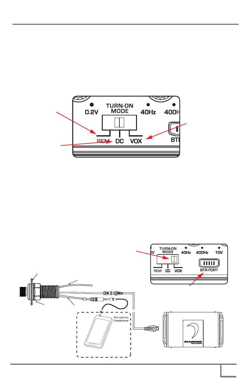
4.TURN-ON OPTIONS - configure the “Turn-On Mode” switch for desired turn-on trigger. There are 3 modes available on the
Bomber series amplifier, REM, DC and VOX. REM is the standard 12V trigger wire, DC or DC offset, when connected
high level in, will sense differences in ground in your wiring through the speaker leads and turn on amplifier, VOX (signal
sensing) will sense any kind of signal input into the amplifier RCA turning on the amplifier. Select VOX when using any
DIAMOND AUDIO Bluetooth Controller. The most preferred and reliable method is using the REM setting with a 12V
trigger wire connected to the vehicles ignition and will provide instant on and off for the amplifier. VOX and DC will provide
turn on capabilities for the amplifier when a 12V trigger wire is not available. These methods will have some delay in
turning the amplifier on and off.
5. BTR Port – (Bluetooth Receiver Port) This port is specifically to be used with any DIAMOND AUDIO Bluetooth controller.
This will allow direct plug in to the amplifier and control simple functions of music playback through the BTR receiver. The
supplied cable is the ONLY cable that can be used to plug into the BTR port on the amplifier. Connecting any other
non-approved cable into the BTR port of the amplifier can cause damage to the amplifier and not be covered under
warranty. The BTR will pair to your phone or selected BT device and will allow playback through the amplifier to speakers
giving you unlimited install options. Play, Pause, Volume up/down, track up/down, Pairing and power on/off of BT
audio through this one solution. Once paired, the BTR will auto pair the last person paired to the controller when it was
powered down. The unit will remember up to 9 users and have memory without battery for up to 30 days.
REMEMBER: When connecting a DIAMOND AUDIO controller using the BTR port select the turn on option to VOX.
REMOTE IN (YELLOW)
MICRO PORT CABLE
NUT
DASH
REAR MOUNT
AUX IN






NOTE: MAKE SURE TO SET





10
SYSTEM CONFIGURATIONS
5. Prepare the ground wire for attachment to the amplifier by stripping 5/8" of insulation from the end of the wire. Always
use a wire of the same gauge as the power connection, never smaller. Insert the bare wire into the GND terminal and
tighten the set screw to secure the cable in place. Prepare the chassis ground by scraping any paint from the metal
surface and thoroughly clean the area of all dirt and grease. Strip the other end of the wire, crimp and soldier a ring
connector. Fasten the cable to the chassis using a non-anodized screw with a star washer and a nut.
WARNING: It is important to upgrade the ground connection
between the negative (-) battery post and the vehicle body or
chassis to achieve optimum electrical performance.
6. Prepare the REM turn-on wire for attachment to the amplifier
by stripping 5/8 inch (15.9mm) of insulation from the end
of the wire. Insert the bare wire into the REM terminal and
tighten the set screw to secure the wire in place. Connect the
other end of the REM wire to a switched 12 volt positive
source. The switched voltage is usually taken from the
source unit's remote amp turn on lead. If the source unit
does not have this output available, the recommended
solution is to wire to an accessory terminal in the car's fuse
block using a relay to isolate the amplifier from the vehicles
accessory circuit. This however will turn the amplifier on and
off with the ignition key, regardless of whether the car stereo
is on or off.
7. Securely mount the amplifier to the vehicle or amp rack. Be careful not to mount the amplifier on cardboard or plastic
panels. Doing so may enable the screws to pull out from the panel due to road vibration or sudden vehicle stops.
8. Connect from source signal by connecting the RCA audio cables to the input jacks at the amplifier.
FRONT INPUT
SIGNAL HARNESS
MICRO4V2 SIGNAL ENDPLATE
MICRO4V2 POWER/SPEAKER ENDPLATE
FRONT OUTPUT
SPEAKER HARNESS
REAR INPUT
SIGNAL HARNESS
REAR OUTPUT
SPEAKER HARNESS
MICRO4V2- 4 CHANNEL CONFIGURATION
STEREO FRONT/REAR SETUP
HEAD UNIT
(PREFERABLY WITH 5V OUTPUT)
BATTERY
PREAMP OUT
FRONT
PREAMP OUT
REAR
STEREO FULL-RANGE
SPEAKERS -
FRONT AND REAR
11
SYSTEM CONFIGURATIONS
MICRO4V2 - FULL MARINE/HOT ROD
SYSTEM WITH BTR
MICRO4V2 SIGNAL ENDPLATE
MICRO4V2 POWER/SPEAKER ENDPLATE
FRONT OUTPUT
SPEAKER HARNESS
REAR OUTPUT
SPEAKER HARNESS
SMARTPHONE
(BLUETOOTH)
DABTR
(BLUETOOTH RECEIVER)
SPECIAL BTR CABLE
(INCLUDED WITH BTR)
8 - 8 INCH HXM8
EXTREME HIGH OUTPUT
2-WAY SPEAKER
(wired 2 ohms ALL channels)
FRONT
REAR
BATTERY
12
SYSTEM CONFIGURATIONS
MICRO1V2 - Monoblock
Subwoofer(s)
MICRO1V2 SIGNAL ENDPLATE
MICRO1V2 POWER/SPEAKER ENDPLATE
SPEAKER OUTPUT
HARNESS
INPUT SIGNAL
HARNESS
MICRO2V2 - Stereo 2 ohms
w/4 speakers
MICRO2V2 SIGNAL ENDPLATE
MICRO2V2 POWER/SPEAKER ENDPLATE
INPUT SIGNAL
HARNESS
SPEAKER OUTPUT
HARNESS

SPEAKER LEVEL INPUT (OPTIONAL):
BRIDGING STEREO/4 CHANNEL AMPS







SUB PRE OUTPUT
FROM HEADUNIT
HEAD UNIT
(PREFERABLY WITH 5V OUTPUT)
BATTERY
SUBWOOFER
HEAD UNIT
(PREFERABLY WITH 5V OUTPUT)
BATTERY
STEREO FULL-RANGE
SPEAKERS - 2 PAIR
IN PARALLEL (2 OHMS)
USE THE LEFT - AND THE RIGHT +
13
SYSTEM CONFIGURATIONS
MICRO5V2 - 5 CHANNEL SYSTEM
MICRO5V2 SIGNAL ENDPLATE
FRONT INPUT
SIGNAL HARNESS
REAR INPUT
SIGNAL HARNESS
MICRO5V2 POWER/SPEAKER ENDPLATE
FRONT AND REAR
CO-AXIALS/COMPONENTS
(4 Ohms OR 2 Ohms)
SUBWOOFER(s)
(4 Ohms OR 2 Ohms)
HEAD UNIT
(PREFERABLY WITH 5V OUTPUT)
PRODUCT SPECIFICATIONS
SPECIFICATIONS
14
MICRO1V2 MICRO2V2
MICRO4V2 MICRO5V2
80 W X 4/200 W X 1
150 W X 4/350 W X 1
300 W X 2/200 W X 1
200mV - 10.0V 200mV - 10.0V 200mV - 10.0V 200mV - 10.0V
950 W RMS
40Hz - 400Hz 40Hz - 400Hz 40Hz - 400Hz 40Hz - 400Hz
60A
40Hz - 400Hz 40Hz - 400Hz Flat or Fixed 70Hz
300 W
175 W
500 W
300 W
175 W
7.89” x 4.0” x 1.46” 7.89” x 4.0” x 1.46”
9.07” x 4.0” x 1.46” 10.65” x 4.0” x 1.46”
200.5 x 103 x 37.2 200.5 x 103 x 37.2
230.5 x 103 x 37.2 270.5 x 103 x 37.2
15
LIMITED WARRANTY STATEMENT
THIS WARRANTY IS NOT TRANSFERABLE AND APPLIES ONLY TO THE ORIGINAL PURCHASER OF THIS PRODUCT
IN ITS ORIGINAL INSTALLATION. Original purchaser must reside in the United States and be able to provide proof of
purchase and installation with the sales receipt and completion of online registration from the authorized DAT retailer that
sold and installed the product.
Should a manufacturing defect occur during above said warranty period, DAT will replace or repair the defective product
with a product of the same or equivalent value and performance, at DAT’s discretion.
Damage or failure caused by any of the following is not covered under this warranty policy: negligence, improper use,
abuse, product modification, unauthorized repair attempts, accident, acts of God, misrepresentations by DAT retailers, and
improper/inadequate packaging during return shipping.
Warranty is void if serial numbers have been removed, altered or defaced.
HOW TO OBTAIN WARRANTY SERVICE
In the event a DAT product should require service, you should visit the authorized DAT retailer you purchased the product
from and they can expedite your claim. All claims must fall into the guidelines listed above and be accompanied by a copy of
the original sales and installation receipt from that authorized DAT retailer.
Product returned for warranty service must be freight-prepaid, properly packaged and clearly marked with the Return
Authorization (RA) number issued by DAT. Any product returned to DAT that is improperly packaged, does not have a
RA number clearly marked on the package, or never received a RA number may be refused upon delivery. DAT does not
assume responsibility for lost or misdirected product.
Repair or replacement under this warranty is the exclusive remedy of the consumer. DAT shall not be liable for any
incidental or consequential damages for breach of any expressed or implied warranty on this product. Some states do not
allow the exclusion or limitation of incidental or consequential damages, or allow limitations on how long an implied warranty
lasts, so the above limitations or exclusions may not apply to you. This warranty gives you specific legal rights and you may
also have other rights that may vary from state to state.
Customers outside the United States should contact their local sales office to obtain information on pricing, exchange unit
availability, instructions, service and warranty/non-warranty replacement or repair.
Diamond Audio Technologies
1225 E.7th ST
LOS ANGELES,CA 90021
Tel: 213-261-4161
Fax: 213-947-4767
Web: diamondaudio.com
Service/Tech Support:
213-261-4161
Tech Support Email
Diamond Audio Technologies (DAT), a division of CV & DA Holdings Incorporated, warrants this product to be free from
defects in material and workmanship for a period of one (1) year from the original date of purchase, provided it was
purchased from an authorized DAT retailer within the United States. Product warranty period starts at the date of
purchase or one year past the manufacture date whichever is first. However, upon purchase and completion of the
on-line registration and installation by an authorized DAT dealer you warranty period will be extended to two (2) years.
This warranty extension offer will only be recognized upon completion of the on-line registration of your product within
thirty (30) days of the date of purchase.
www.DiamondAudio.com
®
1225 E. 7th Street
Los Angeles, CA. 90021
©2015 Diamond Audio. All rights reserved.
(a division of CV & DA Holdings, Inc.)
  • Page 1 1
  • Page 2 2
  • Page 3 3
  • Page 4 4
  • Page 5 5
  • Page 6 6
  • Page 7 7
  • Page 8 8
  • Page 9 9
  • Page 10 10
  • Page 11 11
  • Page 12 12
  • Page 13 13
  • Page 14 14
  • Page 15 15
  • Page 16 16

Diamond MICRO4V2 Owner's manual

Category
Car audio amplifiers
Type
Owner's manual
This manual is also suitable for

Ask a question and I''ll find the answer in the document

Finding information in a document is now easier with AI