ESAB EPP-450 Plasma Power Source User manual

Type
User manual
14
TOUTE DÉCHARGE ÉLECTRIQUE PEUT ÊTRE MORTELLE !
RIFIEZ DE LAISSER UN ESPACE ENTRE LES BORNES À BAGUE, LE
PANNEAU LARAL ET LE TRANSFORMATEUR PRINCIPAL. CET ESPA
CE DOIT ÊTRE SUFFISANT POUR ÉVITER TOUT ARC ÉLECTRIQUE ÉVEN
TUEL. VÉRIFIEZ QUE LES CÂBLES NE GÊNENT PAS LA ROTATION DU
VENTILATEUR DE REFROIDISSEMENT.
UNE PRISE DE TERRE INCORRECTE PEUT ENTRAÎNER DE GRAVES BLES
SURES POUVANT MÊME ÊTRE MORTELLES.
LE CHÂSSIS DOIT ÊTRE CONNECTÉ À UNE PRISE DE TERRE HOMOLO
GUÉE. ASSUREZVOUS QUE LE FIL DE TERRE N’EST PAS BRANCHÉ À
UNE BORNE PRINCIPALE.
TOUTE DÉCHARGE ÉLECTRIQUE PEUT ÊTRE MORTELLE ! TENSION ET
COURANT DANGEREUX !
AVANT DE TRAVAILLER SUR UNE SOURCE D’ÉNERGIE POUR DÉCOUPE
AU PLASMA AVEC LES COUVERCLES RETIRÉS :
• DÉBRANCHEZ LALIMENTATION AU NIVEAU DE L’INTERRUPTEUR
MURAL.
• DEMANDEZ À UN TECHNICIEN QUALIFIÉ DE VÉRIFIER LES BARRES
OMNIBUS DE SORTIE (POSITIVES ET NÉGATIVES) AVEC UN VOLT-
MÈTRE.
3.5 Branchements de sortie
DANGER
DANGER
DANGER
3.5.1 Câbles de sortie (fournis par le client)
Sélectionnez les câbles de sortie de découpe au plasma (fournis par le client) sur la base d’un câble en cuivre
isolé de 4/0 AWG, 600 V pour chaque 400 A de courant en sortie. Pour 450 ampères à 100 % de la capacité de
découpe, deux cables en parallèle de taille 2/0 AWG de 600 volts devraient être utilisés.
Remarque :
N’utilisez aucun câble de soudure isolé de 100 V.
SECTION 3 INSTALLATION
3.5.2 Procédure de branchements de sortie - Alimentation simple
1. Retirez le panneau d’accès sur la partie inférieure avant de la source d’énergie.
2. Faites passer les câbles de sortie par les ouvertures situées sur la partie inférieure du panneau avant ou à la base de la
source d’alimentation située directement derrière le panneau avant.
3. Branchez les câbles aux bornes appropriées situées à l’intérieur de la source d’alimentation à l’aide de connecteurs à
pression pour câbles portants le label UL.
4. Remettez en place le panneau retiré dans la première étape.
30
SECTION 4 FONCTIONNEMENT
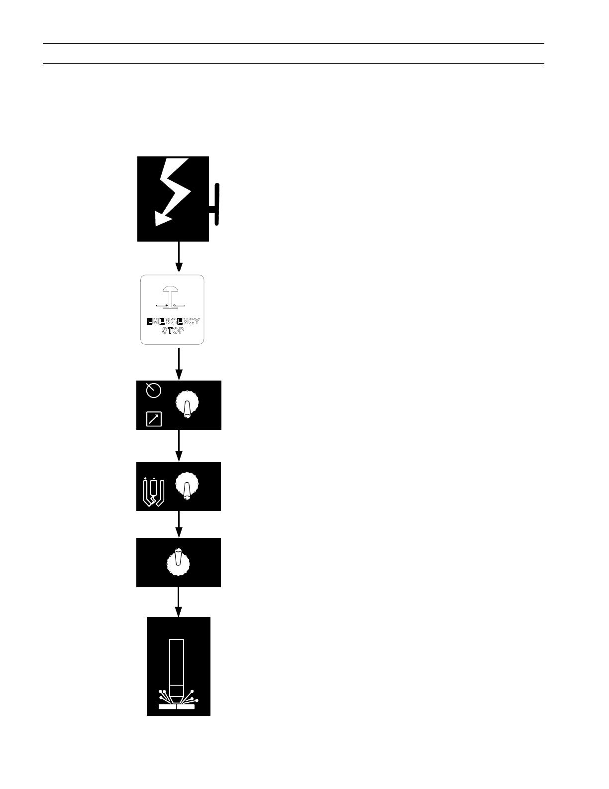
1. Mettez sous tension en fermant l’interrupteur mural de la ligne.
(L’EPP-401/450 nest pas équipé d’un interrupteur de marche/
arrêt). Le témoin d’alimentation principale va séclairer et le
témoin de défaillance va clignoter avant de séteindre.
2. Le bouton d’arrêt d’urgence est tiré.
3. Positionner l’interrupteur Panel / Remote (panneau / à dis-
tance).
4. Positonner le commutateur HIGH / LOW (Haute / Basse) de l’arc
pilote. Si ce dernier est sélectionné par commande à distance,
il doit se trouver en position basse. (Consultez les données
de découpe présentées dans le manuel de la torche.)
5. En mode de panneau, contrôlez la tension préétablie par l’in-
termédiaire du commutateur ACTUAL / PRESET AMPS. Réglez
l’intensité jusqu’à ce que la valeur désirée approximative soit
visible sur l’ampèremètre. En mode de commande à distance,
le positionnement du commutateur à bascule ACTUAL AMPS
/ PRESET AMPS sur la position PRESET AMPS fournira la sortie
initiale de courant commandée à distance.
6. Commencez la découpe au plasma. Cette opération peut
inclure le paramétrage manuel d’autres options en fonction
de l’ensemble du kit plasma.
7. En mode de panneau, réglez l’intensité du courant désirée
après le démarrage du processus de découpe.
8. En cas de panne de démarrage de la découpe ou du mar-
quage, vériez le témoin de défaillance. Si l’un d’eux s’allume,
consultez la section relative au dépannage.
Remarque :
Le témoin de défaillance clignote lors de la première
mise sous tension du contacteur signiant que le
bus c.c. a été normalement alimenté.
4.3 Séquence du fonctionnement
SECTION 4 Operation
ESP 400C Plasma Power Source
ESP 400C Plasma Power SourceESP 400C Plasma Power Source
ESP 400C Plasma Power Source
4-4
Begin
Cutting
ACTUAL AMPS
PRESET AMPS
HIGH
LOW
PILOT
ARC
PANEL
REMOTE
Apply Power
4.3 Sequence of Operation
1. Apply power by closing the line (wall) switch.
(The ESP-400C does not have an on/off
switch). The main power light will illuminate
and the fault light will flash and then go out.
2. Select the Panel/Remote setting.
3. Set pilot arc High/Low switch. (Refer to cutting
data in the torch manual.)
4. If using panel mode, view preset amps with the
ACTUAL/PRESET AMPS switch. Adjust current
until the approximate desired value is shown on
the ammeter.
5. Begin plasma cutting operation. This may
include manually setting up other options,
depending on the total plasma package.
6. If using panel mode, after cutting has begun,
adjust current to desired amount.
7. Check for fault light. If a fault light illuminates,
refer to troubleshooting section.
Note: The fault light flashes when the contactor is
Note: The fault light flashes when the contactor isNote: The fault light flashes when the contactor is
Note: The fault light flashes when the contactor is
first turned on signifying the DC Bus powered up
first turned on signifying the DC Bus powered upfirst turned on signifying the DC Bus powered up
first turned on signifying the DC Bus powered up
normally.
normally.normally.
normally.
4.4 Arc Initiation Settings
The time to achieve full current can be adjusted to
suit your particular system. This feature uses 50%
of the cutting current to start, dwell and then
gradually (less than a second) achieve full current.
The ESP-400C is factory shipped with this feature
enabled. The default settings are:
Minimum Start Current 40A
Start Current 50% of cut current
Timing to achieve full current 800 msec
Dwell Time 50 msec
35
SECTION 5 MAINTENANCE
5.1 General
ELECTRIC SHOCK CAN KILL!
SHUT OFF POWER AT THE LINE WALL DISCONNECT BEFORE AT
TEMPTING ANY MAINTENANCE.
WARNING
WARNING
EYE HAZARD WHEN USING COMPRESSED AIR TO CLEAN.
• Wear approved eye protection with side shields when cleaning the
powersource.
• Useonlylowpressureair.
CAUTION
Maintenance On This Equipment Should Only Be Performed By
Trained Personnel.
5.2 Cleaning
Regularlyscheduledcleaningofthepowersourceisrequiredtohelpkeeptheunitrunningtroublefree.Thefrequencyof
cleaningdependsonenvironmentanduse.
1. Turnpoweroatwalldisconnect.
2. Removesidepanels.
3. Uselowpressurecompresseddryair,removedustfromallairpassagesandcomponents.Payparticularattentionto
heatsinksinthefrontoftheunit.Dustinsulates,reducingheatdissipation.Besuretoweareyeprotection.
36
SECTION 5 MAINTENANCE
Air restrictions may cause EPP-450 to over heat.
Thermal Switches may be activated causing interruption of func-
tion.
Do not use air lters on this unit.
Keep air passages clear of dust and other obstructions.
WARNING
CAUTION
5.3 Lubrication
• Someunitsareequippedwithoiltubesonthefans.Thesefansshouldbeoiledafter1yearofser-
vice.
• AllotherEPP-450shavefanmotorsthatarepermanentlylubricatedandrequireno regularmainte-
nance.
ELECTRIC SHOCK HAZARD!
BE SURE TO REPLACE ANY COVERS REMOVED DURING CLEANING
BEFORE TURNING POWER BACK ON.
37
SECTION 6 TROUBLESHOOTING
6.1 General
ELECTRIC SHOCK CAN KILL!
DO NOT PERMIT UNTRAINED PERSONS TO INSPECT OR REPAIR THIS
EQUIPMENT. ELECTRICAL WORK MUST BE PERFORMED BY AN EXPE
RIENCED ELECTRICIAN.
WARNING
Stop work immediately if power source does not work properly.
Have only trained personnel investigate the cause.
Use only recommended replacement parts.
CAUTION
6.2 Fault Indicators
FaultindicatorsarefoundonthefrontpanelUsedwith
theLEDsonPCB1(locatedbehindthecoverwiththe
EPPlabel)problemscanbediagnosed.
NOTE:
Itisnormalfor momentary light-
ing(ashing)ofthefaultindicator
andLED3whena“contactoron”
signalisappliedatthebeginning
ofeachcutstart.
FaultIndicatorusedwith:
LED3-BusRipple
LED4-HighBus
LED5-LowBus
LED7-ArcVoltageSaturation
LED8-ArcVoltageCuto
PowerResetFaultIndicatorusedwith:
LED6-RightOvercurrent
LED9-LeftOvercurrent
LED10-LeftIGBTUnsaturated
LED11-RightIGBTUnsaturated
LED12-Left-12VBiasSupply
LED13-Right-12VBiasSupply
PCB1 Located behind
thispanel.
Front Panel Fault
Indicators
38
SECTION 6 TROUBLESHOOTING
FaultIndicator(FrontPanel)
Illuminateswhenthereareabnormalitiesinthecuttingprocessorwhentheinput
voltagefalls±10%outsidethenormalvalue.Momentaryilluminationisnormal.If
continuouslylit,checkLEDs3,4,5,7,and8onPCB1forfurtherdiagnosis.
38
LED3–(yellow)BusRippleFault-Momentarilyilluminatesatthebeginningof
eachcut.Continuouslylitduringsingle-phasingorimbalancedline-to-linevolt-
agesofthethreephaseinputline(ExcessiveRipple).PowerSourceisshutdown.
LED4–(yellow)HighBusFault–Illuminateswheninputlinevoltageistoohigh
forproperoperation(approximately20%abovenominalline voltagerating).
Powersourceisshutdown.
LED5–(yellow)LowBusFault–Illuminateswheninputline
voltageislowerthan10%belownominallinevoltagerating.
PowerSourceisshutdown.
LED7–(yellow)ArcVoltageSaturationFault–Illuminates
whenthecuttingarcvoltageistoohighandcuttingcurrent
dropsbelowpresetlevel.LEDwill extinguishaftervoltage
decreasesandcurrentrises.
LED8–(yellow)ArcVoltageCutoFault–Illuminateswhen
arcvoltageincreasesoverthepresetvalue.PSisshutdown.
39
SECTION 6 TROUBLESHOOTING
PowerResetFaultIndicator(onfrontpanel)
Illuminateswhenaseriousfaultisdetected.Inputpowermustbedisconnectedfora
least5secondstoclearthisfault.CheckPCB1RedLEDs6,9,10,11,12,and13ifthis
faultisilluminatedforfurtherdiagnosis.
LED6–(red)RightOvercurrentFault–Illuminateswhenthecurrentoutoftheright
sidechopperistoohigh(300amps).Thiscurrentismeasuredbytheright-sidehall
sensor.Thepowersourceisshutdown.
LED9–(red)LeftOvercurrentFault–Illuminateswhenthecurrentfromtheleftside
chopperistoohigh(300amps).Measuredbythelefthallsensor.Powersourceis
shutdown.
LED10_(red)LeftIGBTUnsaturatedFault–IlluminateswhenleftIGBTisnotfully
conducting.PS(PS)isshutdown.
LED11–(red) RightIGBTUnsaturatedFault –Illuminates
whenrightIGBTisnotfullyconducting.PowerSource(PS)
isshutdown.
LED12–(red)Left-(neg)12VBiasSupplyFault–Illuminates
whennegative12Vbias supplytothe leftside IGBTgate
drivecircuit(locatedonPWM-driveboardPCB2)ismissing.
PSisshutdown.
LED13–(red)Right–(neg)12VBiasSupplyFault-Illuminateswhennegative12Vbias
supplytotherightsideIGBTgatedrivecircuit(locatedonPWMdriveboardPCB3)is
missing.PSisshutdown.
40
SECTION 6 TROUBLESHOOTING
6.3 Fault Isolation
Manyofthemostcommonproblemsarelistedbysymptom.
6.3.1 Nooutputwithcontactorsignalapplied
6.3.2 Outputlimitedto100A
6.3.3 Fansnotworking
6.3.4 Powernotonorlowvoltage
6.3.5 Faultlightillumination
6.3.6 Torchwon’tre
6.3.7 Fussesblown-F1andF2
6.3.8 Intermittent,interruptedorpartialoperation
6.3.3 Fans Not Working
Problem Possible Cause Action
All4fansdonotrun
Thisisnormalwhennotcutting.
Fans run only when “Contactor On”
signalisreceived.
None
1,2or3fansdonotrun.
Broken or disconnected wire in fan
motorcircuit.
Repairwire.
Faultyfan(s) Replacefans
6.3.1 No output with contactor signal applied
Problem Possible Cause Action
Contactor signal is applied,
contactor lamp on front
panelis illuminated,K2and
K3 contactors do not close
andlowbus faultlight,LED
5illuminates.
External emergency stop (E-stop) is
open.
ConnectisolatedcontactofE-stopswitchtopro-
videconnectionbetweenJ1-EandJ1-F.
E-stopbuttononfrontpanelispushed
in.
TwistandpullouttoresetE-stopcondition.
Powerresetlamponfrontpanelindi-
catesaseriousfaultcondition.
Refertosectionunderfaultlightillumination.
6.3.2 Output limited to 100A
Problem Possible Cause Action
Powersourcewillnotgoover
100A.
Highcurrentrangesignalmissing.
ExternalcontrolshouldconnectJ1-RtoJ1-T.As
analternative,inthepowersource,movethered
wireonTB8-1toTB8-2.
41
6.3.4 Power Not On or LOW Voltage
Problem Possible Cause Action
Powersourceinoperable:
Mainpowerlampiso.
Missing3-phaseinputvoltage
Restoreall3 phases ofinputvoltage towithin
±10%ofnominalline.
Missing1of3-phaseinputvoltage
Restoreall3 phases ofinputvoltage towithin
±10%ofnominalline.
Lowopencircuitvoltage
FuseF3/F4blown ReplaceF3/F4
PilotarcContactor(K4)faulty ReplaceK4
FaultyControlPCB1 ReplaceControlPCB1(P/N
0558038312
)
Problem Possible Cause Action
Faultlightilluminatesattheendof
cutbutgoesoatthestartofthe
next.
Normalconditioncausedwhenter-
minatingthearcbyrunningthetorch
otheworkorthearcbeingattached
toapartthatfallsaway.
Reprogramcuttingprocessto
ensurearcisterminatedonlyby
removingtheContactorOn”signal.
LED3–(amber)BusRipple
Imbalanceof3-phaseinputpower
Maintainphasevoltageimbalance
oflessthan5%.
Momentary loss of one phase of
inputpower
Restoreandmaintaininputpower
within±10%nominal
FaultycontrolPCB1 ReplacePCB1P/N
0558038312
LED4–(amber)HighBus
Oneormorephasesofinputvoltage
exceednominallinevoltagebymore
than15%.
Restoreandmaintainlinevoltage
within±10%
FaultycontrolPCB1 ReplacePCB1P/N
0558038312
Oneormoreshorteddioderectiers
(D25-D28)onthe“ElectrodePlate
Replaceshorteddioderectiers
LED5–(amber)LowBus
One or more phases of inputvolt-
agearelowerthannominalbymore
than15%.
Restoreandmaintainwithin
±10%ofnominal
BlownF1andF2fuses
SeeF1andF2inBlown
FusesSection
OvertempLightcomeson. SeeovertempinFaultLightSection
Imbalanced3-phaseinput
power
Maintainphasevoltageimbalance
oflessthan5%
Momentary loss of one phase of
inputpower
Restoreandmaintainwithin
±10%ofnominal
FaultyMainContactor(K1) ReplaceK1
FAULTYControlPCB1 ReplacePCB1P/N
0558038312
SECTION 6 TROUBLESHOOTING
6.3.5 Fault Light Illumination
42
SECTION 6 TROUBLESHOOTING
Problem Possible Cause Action
LED 6 – (red) Right Over Cur-
rent
Note:
Ifoperationat275Aorlessis
possible,thentheLEFTsideis
notworking.
Cuttingatover275Awithafaultyleftside
(leftsideoutput=0)
Seefaultyleftorrightside
Rightcurrenttransducerconnectorloose
orunplugged.PCBloose.
Secureconnections
Loose or unplugged connector at right
PWM/DrivePrintedcircuitboard.
Secureconnection
P2atleftofPWM/DrivePCBlooseorun-
plugged.
Secureconnection
CheckvoltagebetweenP7-6andP7-7.A
voltage in either polarity of greater than
0.01Vindicatesafaultyrightcurrenttrans-
ducer(TD2).
Replace right current transducer
(TD2)
FaultyPCB1 ReplacePCB1P/N
0558038312
FaultyrightPWM/DrivePCB
Replace right PWM / Drive PCB P/N
0558038324
LED9–(red)LeftOverCurrent
Note:
Ifoperationat275Aorlessis
possible,thentheRightsideis
notworking.
Cuttingatover275Awithafaultyrightside
(rightsideoutput=0)
Seefaultyrightside
Leftcurrenttransducerconnectorlooseor
unplugged.PCBloose.
Secureconnections
LooseorunpluggedconnectoratleftPWM
/DrivePrintedcircuitboard.
Secureconnection
P2 at right of PWM / Drive PCB loose or
unplugged.
Secureconnection
CheckvoltagebetweenP7-2andP7-3.A
voltage in either polarity of greater than
0.01Vindicatesafaultyleftcurrenttrans-
ducer(TD1).
Replaceleftcurrenttransducer(TD1)
FaultyPCB1 ReplacePCB1P/N
0558038312
FaultyleftPWM/DrivePCB
Replace left PWM / Drive PCB P/N
0558038324
NEVER attempt to power-up or operate the power source with any
Gate / Emitter IGBT Plug disconnected from its PWM / Gate Drive
Board. Attempting to operate the power source with any open (un-
plugged) IGBT Gate / Emitter Connector may damage the IGBT and
the plasma cutting torch.
CAUTION
43
SECTION 6 TROUBLESHOOTING
Problem Possible Cause Action
VeryhighOutputcurrentac-
companiedbyeitheraleftor
rightovercurrent(LED6)
ShortedIGBT ReplacetheIGBTs
Currentpotsettoohigh Lowerthecurrentsetting
FaultyleftPWM/DrivePCB ReplaceleftPWM/DrivePCB
Highremotecurrentsignal Decreaseremotecurrentsignal
FaultyPCB1 ReplacePCB1P/N0558038312
LED10-(red)LeftIGBTUn-
saturated
BlackwireconnectingIGBT(Q2)collectortoP3ofthe
leftPWM/DrivePCB(PCB2)isdisconnected.
Secureconnector
ShortedFreewheelingDiode(s) Replacefreewheelingdiode(s)
LooseorunpluggedP1connectorattheleftPWM/
DrivePCB
SecureP1
LooseorunpluggedP10connectoratPCB1 SecureP10
FaultyPCB1 ReplacePCB1P/N0558038312
FaultyleftPWM/DrivePCB ReplacePCB2P/N0558038324
LED 11 - (red) Right IGBT
Unsaturated
BlackwireconnectingIGBT(Q5)collectortoP3ofthe
rightPWM/DrivePCB(PCB3)isdisconnected.
Secureconnector
ShortedFreewheelingDiode(s) Replacefreewheelingdiode(s)
LooseorunpluggedP1connectorattheleftPWM/
DrivePCB
SecureP1
LooseorunpluggedP10connectoratPCB1 SecureP11
FaultyPCB1 ReplacePCB1P/N0558038312
FaultyrightPWM/DrivePCB ReplacePCB3P/N0558038324
44
SECTION 6 TROUBLESHOOTING
Problem Possible Cause Action
LED12–(red)Left–12VMissing
LooseorunpluggedP1connectorat
theleftPWM/DrivePCB
SecureP1connector
Loose or unplugged P10 connector
atPCB1
SecureP10connector
FaultyleftPWM/DrivePCB
Replace left PWM / Drive PCB P/N
0558038324
LED12–(red)Right–12VMissing
LooseorunpluggedP1connectorat
therightPWM/DrivePCB
SecureP1connector
Loose or unplugged P11 connector
atPCB1
SecureP11connector
FaultyrightPWM/DrivePCB
Replace right PWM / Drive PCB P/N
0558038324
VeryhighOutputcurrentaccompa-
niedbyeitheraleftorrightovercur-
rent(LED9orLED6respectively)
ShortedIGBT ReplacetheIGBTs
Currentpotsettoohigh Lowerthecurrentsetting
FaultyleftPWM/DrivePCB
Replace left PWM / Drive PCB P/N
0558038324
Highremotecurrentsignal Decreaseremotecurrentsignal
FaultyPCB1 ReplacePCB1P/N0558038312
OverTempLampilluminates
Oneormorefansinoperable Repairorreplacefan(s)
Brokenwireorunpluggedconnector
atthermalswitch.
Repair broken wires andunplugged con-
nector
Obstructiontoairowcloserthan3feet
(1m)torearofpowersource.
Allow3ft.(1m)minimumbetweentherear
ofthepowersourceandanyobjectthatmay
restrictairow.
Excessive dirt restricting cooling air
ow
Cleanout excessive dirt, especiallyinthe
extrusionsfortheIGBTsandfreewheeling
diodes,thePOS,NEGandElectrodePlates,
the main transformer (T1) and the lter
inductors(L1andL2).
Obstructedairintake
Checkandclearanyobstructionsfromthe
bottom, front, and top rear of the Power
Source.
45
SECTION 6 TROUBLESHOOTING
6.3.6 Torch Will Not Fire
Problem Possible Cause Action
MainArcTransferstothe workwitha
short“pop,placingonlyasmalldimple
inthework.
Remote control removes the start
signalwhen the mainarc transfersto
thework.
Panel/Remoteswitchin“Remotewith
noremotecontrolofthecurrent
Place Panel/Remote switch in“Panel”
position
Remote current control present but
signalmissing.
CheckforcurrentreferencesignalatTB1-
4(+)andTB1-5(-).SeeSignalvs.Output
CurrentCurvethissection.
Currentpotsettoolow. Increasecurrentpotsetting.
Start current pot, located behind the
cover for the control PCB is set too
low.
Increasethestartcurrentpostsetting
to“7”.
Arcdoesnotstart.Thereisnoarcatthe
torch.OpencircuitvoltageisOK.
Openconnectionbetweenthepower
sourcepositiveoutputandthework.
Repairconnection
FuseF6inthePilotarccircuitisblown. ReplaceF6
FuseF7inthepilotarccircuitisblown. ReplaceF7
PilotarcHigh/Lowswitchisinthe”LOW
positionwhen usingconsumablesfor
100Aorhigher(Refertoprocessdata
includedintorchmanuals)
Change Pilot arc to “High position.
(Refertoprocessdataincludedintorch
manuals)
Pilotarccontactor(K4)faulty. ReplaceK4
FaultyPCB1
ReplacePCB1P/N
0558038312
46
Problem Possible Cause Action
FusesF1andF2blown.
Processcontrollerignitespilotarctoo
soon after providing the “Contactor
Onsignal
Process controller must allow atleast
300MS tolapse between theapplica-
tion of the“Contactor On signal and
theignitionofthepilotarc.Fixprocess
controllerlogicandreplacediodes.
Faultynegative(Electrode)outputcable
shortingtoearthground.
Repaircable
Shortedfreewheelingdiode.
Replace shorted freewheeling diode
andF1-F2
One or more shorted diode rectiers
(D13-D18)on“POSPlate.
Replacealldioderectiersonthe“POS
P l a t e ”.
One or more shorted diode rectiers
(D7-D12)on“NEGPlate.
Replacealldioderectiersonthe“NEG
P l a t e ”.
SECTION 6 TROUBLESHOOTING
6.3.7 Fuses F1 and F2 Blown
Problem Possible Cause Action
WorksOKat275Aorless-Over
current right side when cutting
over275A.LED6oncontrolboard
illuminated.
LooseorunpluggedconnectoratleftPWM/
DrivePCB(PCB2)
Secureconnector
FaultyleftPWM/DrivePCB
Replace right PWM / Drive PCB P/N
0558038324
CheckvoltagebetweenP5-1andP5-2atthe
leftPWM/DrivePCB(PCB2).Shouldbe20V
AC.BetweenP5-1andP5-3shouldbe40VAC.
Ifnotthecontroltransformer(T5)isfaulty.
ReplacecontroltransformerT5
6.3.8 Intermittent, Interrupted or Partial Operation
NEVER attempt to power-up or operate the power source with any
Gate / Emitter IGBT Plug disconnected from its PWM / Gate Drive
Board. Attempting to operate the power source with any open (un-
plugged) IGBT Gate / Emitter Connector may damage the IGBT and
the plasma cutting torch.
CAUTION
WorksOKat275Aorless-Over
current left side when cutting
over275A.LED9oncontrolboard
illuminated.
LooseorunpluggedconnectoratRightPWM
/DrivePCB(PCB3)
Secureconnector
FaultyRightPWM/DrivePCB
Replace right PWM / Drive PCB P/N
0558038324
CheckvoltagebetweenP5-1andP5-2atthe
rightPWM/DrivePCB(PCB3).Shouldbe20V
AC.BetweenP5-1andP5-3shouldbe40VAC.
Ifnotthecontroltransformer(T7)isfaulty.
ReplacecontroltransformerT7
47
SECTION 6 TROUBLESHOOTING
Problem Possible Cause Action
Power Supply turns o prema-
turelyinthemiddleofthecut.
“ContactorOnsignalisremovedfromunit.
PowersourceisOK.Troubleshootpro-
cesscontroller.
Momentarylossofprimaryinputpower.
Restore and maintain input voltage
within±10%ofnominal.
Faulty condition, indicated by illumination
ofthefaultlamp.
RemovecontrolPCB(PCB1)accesspanel
todeterminethefaultcausingtheshut-
down.Refertofaultlightillumination
section.
Faultycondition,indicatedbytheillumination
ofthepowerresetfaultlamp.
RemovecontrolPCB(PCB1)accesspanel
todeterminethefaultcausingtheshut-
down.Refertofaultlightillumination
section.
Currentsettingtoolow. Increasecurrentsetting
Remotecurrentsignalremovedduringcut. Fixremotecurrentsignal
Problem Possible Cause Action
Output current is unstable and
drifts above or below the set-
ting.
PlacethePANEL/REMOTEswitchinthe“PANEL
position.Adjustcurrentcontrolpot.Ifcurrent
nolongerdrifts,theremotecurrentcontrol
signalisfaulty.
Fixtheremotecurrentcontrolsignalto
operatethePANEL/REMOTEswitchin
the“PANELposition.
Select“PANELonthePANEL/REMOTEswitch
andadjustthecurrentcontrolpot.Thecur-
rentstilldrifts,measurethecurrentreference
signalatTB1-4(+)andTB1-5(-).Ifthesignal
drifts,thecurrentcontrolpotisfaulty.Ifthe
signaldoesnotdrift,theControlPCB(PCB1)
isfaulty.
Replacethecurrentcontrolpot.
Replace the control PCB (PCB1) P/N
0558038312
48
SECTION 6 TROUBLESHOOTING
6.4 Testing and Replacing Components
• ReplaceaPCboardonlywhenaproblemisisolatedtothatboard.
• AlwaysdisconnectpowerbeforeremovingorinstallingaPCboard.
• Donotgrasporpullonboardcomponents.
• Alwaysplacearemovedboardonastaticfreesurface.
• IfaPCboardisfoundtobeaproblem,checkwithyourESABdistribu-
torforareplacement.Providethedistributorwiththepartnumberof
theboardaswellastheserialnumberofthepowersource.
• Donotattempttorepairtheboardyourself.Warrantywillbevoidedif
repairedbythecustomeroranunauthorizedrepairshop.
NOTICE
Power Semiconductor Components
Categoriesofpowersemiconductorsinclude;
• PowerRectiers
• ModulescontainingthefreewheelingdiodesandIGBTs
49
SECTION 6 TROUBLESHOOTING
6.4.1 Power Rectiers and Blocking Diodes
1. Removetopcoverandsidepanels
2. Locateanddisconnectpluginrearofammeter(attached
toneredandoneblackwire)
3. Removepilotarcswitch
4. Disconnectvoltmeter
5. DisconnectorangeandyellowwiresfromrelayK4.
6. Removetwoboltsholdingtheleftsideofthefrontpanel
tothebase.
7. Removethreeboltsholdingacrossthecenterbaseofthe
frontpanel.Theseareaccessedfromunderneath.
8. Removeoneoftheboltsholdingtherightsideofthe
front panel to the base. Loosen the second bolt. Of
thesetwobolts,removetheboltontheleftandloosen
theboldontheright.
9. Swingthefrontpanelouttogainaccesstopowerrecti-
ercomponents.
Troubleshooting Procedures –Negative Plate
1. VisuallyinspectfusesF8andF9.Replaceiftheyshowsigns
ofbeingblownormelted.Inspectdiodes.Ifruptured
orburned,replacealldiodesontheNEGPlate.Ifdiodes
appeartobeOK,proceedtonextstep.
LocationofNeg.Plate
LocationoffusesF8andF9
PowerRectiers
Proceduretoaccessbehindthefrontpanel
BlockingDiodes
PowerRectiers
50
SECTION 6 TROUBLESHOOTING
1. CheckohmsbetweenNEGPlateandBRABus.Areading
of2ohmsorlessindicatesoneormoreshorteddiodes.
ReplaceallDiodesonNEGPlate.
2. IffusesF8and/orF9wereopenintherststep,maketwo
moreohmmeterreadings.
 A.MeasureresistancebetweentheNEGPlateand
BR“B”bus.
 B.MeasurebetweenNEGPlateandBR“C”bus.
If resistanceis 2ohms orless ineither case, replace allthe
diodesontheNEGPlate.
POSPlateElectrodePlate
DiodeRectierNEGPlate
LocationofPos.Plate
LocationoffusesF8andF9
Troubleshooting POS Plate
1. CheckohmsbetweenPOSPlateandBRABus.Areading
of2ohmsorlessindicatesoneormoreshorteddiodes.
ReplaceallDiodesonPOSPlate.
2. IffusesF8and/orF9wereopenintherststep,maketwo
moreohmmeterreadings.
A.MeasureresistancebetweenthePOSPlateandBR
“B”bus.
B.MeasurebetweenPOSPlateandBR“C”bus.
If resistanceis 2ohms orless ineither case, replace allthe
diodesonthePOSPlate.
CathodeLeads
Bus
1. Visuallyinspectforrupturedorburneddiodes.Replace
onlythosedamaged.
2. CheckresistancebetweenElectrodePlateandtheparallel
pigtails(cathodeleads)ofD25andD26.Ifreadingis2
ohmsorless,disconnectleadsfrombusandcheckeach
diode.Replaceonlyshorteddiodes.
Repeat procedure for D27 and D28. Replace only shorted
diodes.
Blocking Diodes D25, D26, D27 and D-28
Troubleshooting Electrode Plate
51
SECTION 6 TROUBLESHOOTING
6.4.2 IGBT / Freewheeling Diode (FWD) Replacement
The emitter and the gate of each aected IGBT must be jum-
pered together to prevent electrostatic damage. Each power
source is supplied with six jumper plugs that mate to the IGBT
Gate / Emitter Plug.
CAUTION
Electrostatic Discharge Hazard
Electrostatic discharge may damage these components.
• Damageisaccumulativeandmayonlyappearasshortenedcompo-
nentlifeandnotasacatastrophicfailure.
• Wearaprotectivegroundstrapwhenhandlingtopreventdamage
toPCBcomponents.
• Alwaysplaceapcboardinastatic-freebagwhennotinstalled.
CAUTION
The module gate plugs must be plugged into the PWM/Gate
Drive PC Board whenever the power source is in operation.
Failure to plug them in will result in damage to the module and
possible damage to the torch.
CAUTION
REMOVAL:
A. Insurethatinputpowerisremovedbytwoactionssuchasadisconnectswitchandremovaloffuses.Tagandlockany
disconnectswitchtopreventaccidentalactivation.
B. Removethetoppaneltogainaccesstothemoduleslocatedinthetoprearofthepowersource.
C. Cleanthecompartmentcontainingthemoduleswithdry,oil-freecompressedair.
D. UnplugthegatedriveleadsconnectingtheIGBTGatestothePWM/GateDrivePCBoard.Inordertopreventdamage
totheIGBT,installjumperplugsintotheIGBTGateDriveConnector.SeeCautionbelow.Jumperplugsaresupplied
witheachpowersource.
E. RemovethecopperbussplatesandbarsconnectedtotheIGBT’s.SavetheM6hardwareconnectingthebusstructure
tothemoduleterminals.Youmayneedtore-usethehardware.Longerhardwarecandamagethemodulebycontact-
ingthecircuitrydirectlybelowtheterminals.
F. RemovetheM6hardwaremountingthemodulestotheheatsink.Savethehardwarebecauseyoumayneedtore-use
it.HardwaretooshortcanstripthethreadsintheAluminumheatsink.Hardwaretoolongcanhitthebottomofthe
holescausingthemodulestohaveinsucientthermalcontacttotheheatsink.Hardwaretoolongortooshortcan
causemoduledamageduetooverheating.
52
SECTION 6 TROUBLESHOOTING
REPLACEMENT:
A. Thoroughlycleananythermalcompoundfromtheheatsinkandthemodules.Anyforeignmaterialtrappedbetween
themoduleandheatsink,otherthananappropriatethermalinterface,cancausemoduledamageduetooverheat-
ing.
B. Inspectthethermal(interface)pad,P/N951833,fordamage.Acreaseordeformitycanpreventthemodulefromseat-
ingproperly,impedingtheheattransferfromthemoduletotheheatsink.Theresultcanbemoduledamagedueto
overheating.
Ifathermalpadisnotavailable,aheatsinkcompoundsuchasDowCorning®340HeatSinkCompoundmaybeused.Its
agoodideatomountallparalleledmoduleslocatedonthesameheatsinkusingthesamethermalinterface.Dierent
interfacescancausethemodulestooperateatdierenttemperaturesresultinginun-equalcurrentsharing.Theimbal-
ancecanshortenmodulelife.
C. Placeathermalpad,andanIGBTmoduleontheheatsink.Carefullyaligntheholesinthethermalpadwiththeheat-
sinkandmoduleholes.Ifheatsinkcompoundisusedinplaceofathermalpad,applyathincoatofeventhicknessto
themetalbottomofthemodule.Athicknessof0.002–0.003(0.050mm–0.075mm)isoptimum.Toomuchcom-
poundimpedesheattransferfromthemoduletotheheatsinkresultinginshortmodulelifeduetooverheating.
D. InsertthefourM6mountingbolts,butdonottighten.Leavethemlooseafewturns.Becertainthatthethreadsfrom
themountingboltsdonotbendtheedgesofthethermalpadclearanceholes.Abentthermalpadcanpreventthe
modulefromseatingproperly,impedingtheheattransferfromthemoduletotheheatsink.Theresultcanbemodule
damageduetooverheating.
E. Partiallytightenthefourmountingboltsalittlemorethanngertightintheorder:A-B-C-D.Seegurebelow.
F. Fullytighten,inthesameorderabove,toatorqueof35–44in-lbs(4.0–5.0N-M).Seegurebelow.
G. Installthebusplatesandbusbars.Becarefulthatthesheetsofinsulationseparatingthebusplatesarestillintheir
originalpositions.Itsagoodideatotightenthemountinghardwareonlyaftergettingitallstarted.TorquetheM6
moduleterminalhardwareto35–44in-lbs(4.0–5.0N-M).
H. Removethejumperplugsfromthemodulegateleadplugs,andplugintotheappropriateplugsfromthePWM/Gate
DrivePCBoard.SeeCautionbelow.
I. Replacethetoppanel.
The module gate plugs must be plugged into the PWM/Gate
Drive PC Board whenever the power source is in operation.
Failure to plug them in will result in damage to the module and
possible damage to the torch.
CAUTION
Four-PointMountingType
Partialtightening-A
-B-C-D
Fullytightening-A
-B-C-D
A
D
C
B
1
2
3
6 (RED)
7 (WHT)
Key Plug
Position 1 (RED)
1-IBGTCollector,FreeWheeling
Diode(FWD)Anode
2-IGBTEmitter
3-FWDCathode
6-IGBTGate
7-IGBTEmitter
threeleads
  • Page 1 1
  • Page 2 2
  • Page 3 3
  • Page 4 4
  • Page 5 5
  • Page 6 6
  • Page 7 7
  • Page 8 8
  • Page 9 9
  • Page 10 10
  • Page 11 11
  • Page 12 12
  • Page 13 13
  • Page 14 14
  • Page 15 15
  • Page 16 16
  • Page 17 17
  • Page 18 18
  • Page 19 19
  • Page 20 20
  • Page 21 21
  • Page 22 22
  • Page 23 23
  • Page 24 24
  • Page 25 25
  • Page 26 26
  • Page 27 27
  • Page 28 28
  • Page 29 29
  • Page 30 30
  • Page 31 31
  • Page 32 32
  • Page 33 33
  • Page 34 34
  • Page 35 35
  • Page 36 36
  • Page 37 37
  • Page 38 38
  • Page 39 39
  • Page 40 40
  • Page 41 41
  • Page 42 42
  • Page 43 43
  • Page 44 44
  • Page 45 45
  • Page 46 46
  • Page 47 47
  • Page 48 48
  • Page 49 49
  • Page 50 50
  • Page 51 51
  • Page 52 52
  • Page 53 53
  • Page 54 54
  • Page 55 55
  • Page 56 56
  • Page 57 57
  • Page 58 58
  • Page 59 59
  • Page 60 60
  • Page 61 61
  • Page 62 62
  • Page 63 63
  • Page 64 64
  • Page 65 65
  • Page 66 66
  • Page 67 67
  • Page 68 68

ESAB EPP-450 Plasma Power Source User manual

Type
User manual

Ask a question and I''ll find the answer in the document

Finding information in a document is now easier with AI