BEGLEC DB-46 Owner's manual
- Category
- Stroboscopes & disco lights
- Type
- Owner's manual

PROFESSIONAL
4.6kW POWERED
DMX 4-BAR
WWW.BRITEQ-LIGHTING.COM
Copyright © 2007 by BEGLEC cva.
Reproduction or publication of the content, even portions, in any manner, without express permission of the publisher, is prohibited.
V1.0
R
TFM
R
e
a
d
T
his
Fi
n
e M
a
nual
P 01 ... 06 English
P 07 ... 12 Français
P 13 ... 18 Nederlands
P 19 ... 24 Deutsch
P 25 ... 30 Espagñol

EN - DISPOSAL OF THE DEVICE
Dispose of the unit and used batteries in an environment friendly manner
according to your country regulations.
FR - DÉCLASSER L’APPAREIL
Débarrassez-vous de l’appareil et des piles usagées de manière écologique
Conformément aux dispositions légales de votre pays.
NL - VERWIJDEREN VAN HET APPARAAT
Verwijder het toestel en de gebruikte batterijen op een milieuvriendelijke
manier conform de in uw land geldende voorschriften.
DU - ENTSORGUNG DES GERÄTS
Entsorgen Sie das Gerät und die Batterien auf umweltfreundliche Art und
Weise gemäß den Vorschriften Ihres Landes.
ES - DESHACERSE DEL APARATO
Reciclar el aparato y pilas usadas de forma ecologica conforme a las
disposiciones legales de su pais.
PT - COMO DESFAZER-SE DA UNIDADE
Tente reciclar a unidade e as pilhas usadas respeitando o ambiente e em
conformidade com as normas vigentes no seu país.

Thank you for buying this BriTeQ
®
product. To take full advantage of all possibilities, please read these
operating instructions verycarefully.
This unit is radio-interference suppressed. This product meets the requirements of the current European and
national guidelines. Conformity has been established and the relevant statementsand documents have been
deposited by the manufacturer.
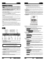
Professional aluminium Powered 4-bar: 4x1,8kW (Max
tot
= 4,6kW/20A)
Sliding mechanism: you can distribute your projectors evenlyover the bar.
Locking DMXin/outputswith POWER/DMX-present indicator
4 Digit LED displaywith 4 buttons for easy menu navigation:
DMXaddress setting: each channelcan haveits own address
Each channel can beseparately switched in dimmer or switch mode
Separate dimmer presetswith memory function for each channel (no controller needed)
4High qualitymains sockets(schuko)
Standard 28mm TV-spigot + 35mm top section adapter included
Mains power input with Neutrik Powercon and automatic fuse
Individual channel fuses with “blown fuse” detectors
All channels equipped with 40Atriacs for increased reliability
Check thecontents:
Check that the carton contains the following items:
DB-46 powered bar
4 sets of bolts and nuts used to install projectors
1 TV-spigot28mm
1 Top section adapter35mm
1 Lifting eye bold
User manual
Some important instructions:
Before you start using this unit, please check if there’s no transportation damage. Should there be any, do
notuse the deviceand consult your dealerfirst.
Important:
This device left our factory in perfect condition and well packaged. It is absolutely necessary
for the user to strictly follow the safety instructions and warnings in this user manual. Any damage caused
bymishandling is not subjectto warranty. The dealer will not accept responsibility for any resulting defects
orproblems caused bydisregarding this user manual.
Keep this booklet in a safe place for future consultation. If you sell the fixture, be sure to add this user
manual.
To protect theenvironment, please try to recyclethe packing material as much as possible.
CAUTION: To reduce the risk of electric shock, do not remove the top cover.
No user-serviceable parts inside. Refer servicing to qualified service
personnel only.
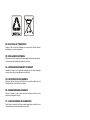
The lightning flash with arrowhead symbol within the equilateral triangle is intended to alert the use
or the presence of un-insulated “dangerous voltage” within the product’s enclosure that may be of
sufficient magnitude to constitute a risk of electric shock.
The exclamation point within the equilateral triangle is intended to alert the user to the presence of
important operation and maintenance (servicing) instructions in the literature accompanying this
appliance.
This symbol means: indoor useonly.
Thissymbol means:Readinstructions.
To prevent fire or shock hazard, do not exposethis applianceto rain ormoisture.
To avoid condensation to be formed inside, allow the unit to adapt to the surrounding temperatures when
bringing it into a warm room after transport. Condense sometimes prevents the unit from working at full
performance or may even cause damages.
This unit is forindoor use only.
Don’t place metal objects or spill liquid inside the unit. Noobjects filled with liquids, such as vases, shall be
placed on this appliance. Electric shock or malfunction may result. If a foreign object enters the unit,
immediately disconnect the mains power.
No naked flame sources, such as lighted candles, should be placed on the appliance.
Preventuse in dusty environments and clean the unit regularly.
Keep the unit away from children.
Inexperienced personsshould not operatethis device.
Maximum saveambient temperature is 40°C. Don’t use this unit athigher ambient temperatures.
Always unplug theunit when it is not used for a longer time orbeforeyou start servicing.
The electrical installation should be carried out by qualified personal only, according to the regulations for
electrical and mechanical safety in your country.
Check that the available voltageis not higher than the one stated on the rear panel of the unit.
The socketinlet shall remain operable for disconnection from the mains.
The power cord should always be in perfect condition: switch the unit immediately off when the power cord
is squashedor damaged.
Never let the power-cord come into contact with other cables!
Thisunitmust be earthed to in order complywith safety regulations.
In order to prevent electric shock, do not open the cover. Apart from the mains fuse there are no user
serviceablepartsinside.
Never repair a fuse or bypass the fuse holder. Always replace a damaged fuse with a fuse of the same
type and electrical specifications!
In the event of serious operating problems, stop using the appliance and contact yourdealer immediately.
Please use the original packing when the device is tobe transported.
Due to safety reasons it is prohibited to make unauthorized modifications to the unit.
Clean by wiping with a polished cloth slightly dipped with water. Avoid getting water inside the unit. Do not
use volatile liquids such as benzene orthinnerwhich willdamage theunit.
CAUTION

Important: The installation must be carried out by qualified service personal only. Improper
installation can result in serious injuries and/or damage to property. Overhead rigging requires
extensive experience! Working load limits should be respected, certified installation materials
shouldbe used, the installed device should be inspected regularlyfor safety.
Make sure the area below the installation place is free from unwanted persons during rigging, de-rigging
andservicing.
Locate the fixture in a well ventilated spot, far away from any flammable materials and/or liquids. The
fixture must be fixed
at least50cm
fromsurrounding walls.
The deviceshould be installed out of reach of people and outside areas where persons may walk by or be
seated.
Before rigging make sure that the installation area can hold a minimum point load of 10times thedevice’s
weight.
Always use a certified safety cable thatcan hold 12times the weight of the device when installing the unit.
This secondary safety attachment should be installed in a way that no part of the installation can drop
more than 20cm if the main attachment fails.
The device should be well fixed; a free-swinging mounting is dangerous and maynotbe considered!
Don’t cover any ventilation openingsas this mayresult in overheating.
The operator has to make sure that the safety-relating and machine-technical installations are approved by
an expert before using them forthe first time. The installations should be inspected every year by a skilled
person to be sure that safety is still optimal.
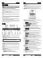
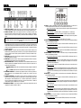
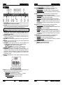
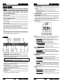
1. CHANNEL OUTPUTS: Each channel output has its own output socket to connect any resistive and/or
inductive projector(s) or small light effects.
2. CHANNELFUSES: Each channel is equipped with afuse and “blown fuse” detector. The detector lights
up when the channel fuse is blown. Always replace the blown fuse with a fuse that has the same
characteristics! (250V/8A).
IMPORTANT NOTE: It’s very important to know that the maximum load for each channel is rated at 8A or
1850Watts. However the total load for all 4 channels may not exceed 20A or 4600Watts!
3. POWER INPUT: mainsinput, equipped with a Neutrik Powercon
®
, make sure thelocal voltage is 230Vac
and the projectors (and/or light effects) are properly connected to the channel output sockets (1) before
you connect an earthed mains cable to this input. The maximum total load is 20A or 4600Watts.
4. INPUT FUSE: This is an automatic circuit breaker. When the fuse is blown, first locate and solve the
problem that caused the fuse to blow. When the problem is solved, simply push the button to reset the
circuit breaker.
5. DMX OUTPUT: 3pin female XLR-connector used to connect the DB-46 with the next unit in the DMX
chain.
6. DMX INPUT: 3pin male XLR-connector used to connect universal DMX-cables. This input receives
instructionsfrom aDMX-controller.
7. STAND ADAPTER: used to put the DB-46 easily on top of a light stand. Two different stand adapters
areincluded (also seenumber 9 for more information):
35mmadapter: tobe used on stands with a standard 35mm top section.
28mm TV-Spigot: to beused on stands equipped with aTV-spigot adapter on top.
8. SLIDING MECHANISM: used to distribute your projectors evenly over the DB-46. Also see number 9 for
more information.
9. ENDCAP: To install the bolts/nuts (needed to fix the projectors) and stand adapter you have to remove
this end cap on oneside of the unit: simply unscrew the 4 screws remove the cap put the nuts/bolts
and/or stand adapter in the sliding rail put thecap back in place fix the 4 screws done!
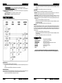
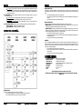
10. CONTROL PANEL: multifunctional display + 4 buttons to navigate the setup menu. See the numbers
below.
11. DISPLAY: shows the information related to the selected function or working mode. The left digit shows
thechannel number,the 3 other digits showthe channel status:
In theaddress menu: channeladdress isshown, ranging from 001to 512
In the mode menu: working mode is shown. (“d” = dimmermode * “S” = switch mode)
In the dim menu and standard display: channel output statusis shown.
Channel in dimmer mode: dimmer percentage, ranging from0% to100%
Channel in switch mode: “oN” = output 100% * “oFF”= output 0%
12. MENU BUTTON: Please refer to the menu structure to understand the different menus. These are the
different possibilities:
Browse the main menu: Press the MENU button togetherwith the UP/DOWN buttons.
Return to the main menu: Pressthe MENU button to return to the main menu. (escapefunction)
Display blackout function: Press the MENU button together with the ENTER button to switch the
display on/off.
13. DOWN BUTTON: Please refer to the menu structure to understand the different menus. These are the
different possibilities:
Browse the main menu: Press the MENU button together with the UP/DOWN buttons.
In the addressmenu: Press the DOWN button to lower the DMX address of the selected channel.
(press the button for a longer time to increase the speed)
In the mode menu: Pressthe DOWN button toput the selected channel in switch mode.
In the dim menu: Press the DOWN button to lower the dimmervalue (0~100%) when the selected
channel is in dimmer mode. (press the button for a longer time to increase the speed). When the
selected channel isset toswitch mode,you can turn theoutput off.
14. UP BUTTON: Please refer to the menu structure to understand the different menus. These are the
different possibilities:
Browse the main menu: Press the MENU button together with the UP/DOWN buttons.
In the address menu: Press the UP button to increase the DMX address of the selected channel.
(press the button fora longertime to increase the speed)
In the mode menu: Press the UP button to put theselected channel in dimmer mode.
In the dim menu: Press the UP button to increase the dimmer value (0~100%) when the selected
channel is in dimmer mode. (press the button for a longer time to increase the speed). When the
selected channel is set to switch mode, you can turn the output on.
15. ENTER BUTTON: Please refer to the menu structure to understand the different menus. These are the
different possibilities:
In the main menu: Pressthe ENTERbutton toselect thedesired sub menu.
In a sub menu: Press the ENTERbutton to browsethrough the 4 channels.
Display blackout function: Press the MENU button together with the ENTER button to switch the
display on/off.
16. DMX PRESENTLED: this LED indicates if the unit receives a DMX-signal on the DMX-input(n°6):
LED is on: noDMX-signal detected onthe input.
LED is blinking: DMX-signal detected on the input

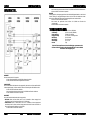
MAINMENU:
This menuis used to select one of the 3 sub menus.
Press theMENU button together with the UP/DOWN buttons to browse the menu.
Press the ENTER button to selectthedesired sub menu.
ADDRESSMENU:
This menu is used to set the DMX address of the 4 output channels. Each channel can be set to a unique
DMX-address. You can even give 2 or more channels thesame DMXaddress.
Press the ENTER button to browse through the menu.
Once you selected the desired channel, press the UP/DOWNbuttons toset theaddress
Press theMENU button to return tothe main menu.
MODEMENU:
Thismenuis used to set the working mode of the 4outputchannels.
DIM mode: use this mode when you connect lamps (projectors) to this output channel. You will be able to
dim theoutput smoothly between 0% and 100%.
SWITCH mode: use this mode when you connect small light effects to this output channel. You can toggle
the output between ON (100% output) and OFF (0% output). Now you can switch small light effects on/off
with your DMX-controller.
Press the ENTER button to browse through the menu.
Once you selected the desired channel,press the UP/DOWNbuttons toset the working mode.
Press theMENU button to return to the main menu.
DIM MENU:
This is the standalone mode, all output levels can be set directly on the control panel so you don’t need a
controller. It’s important to know that the output settings are preserved when the unit is disconnected from
themains. This makes the DB-46 very useful to illuminate exhibition booths etc.
Press the ENTER button to browse through the menu.
Once you selected the desired channel, press the UP/DOWNbuttons toset the output level.
Press theMENU button to return to the main menu.
PowerInput: 230Vac / 20A maximum (4600Watts)
Poweroutputs: 4x 230Vac/ max. 8A (1850Watts)
Channel Fuses: 250V/8A (size 20x5mm)
Input fuse: 20A “auto reset” thermal circuit breaker
DMX input: 3pin XLR male
DMX output: 3pinXLR female
Size: 152 x 9 x 7 cm
Weight: 5,5 kg
Every informationis subject to change withoutprior notice
You can download the latest version of this user manual on our website: www.briteq-lighting.com
Page is loading ...
Page is loading ...
Page is loading ...
Page is loading ...
Page is loading ...
Page is loading ...
Page is loading ...
Page is loading ...
Page is loading ...
Page is loading ...
Page is loading ...
Page is loading ...
-
 1
1
-
 2
2
-
 3
3
-
 4
4
-
 5
5
-
 6
6
-
 7
7
-
 8
8
-
 9
9
-
 10
10
-
 11
11
-
 12
12
-
 13
13
-
 14
14
-
 15
15
-
 16
16
-
 17
17


BEGLEC DB-46 Owner's manual
- Category
- Stroboscopes & disco lights
- Type
- Owner's manual
Ask a question and I''ll find the answer in the document
Finding information in a document is now easier with AI
in other languages
- français: BEGLEC DB-46 Le manuel du propriétaire
- español: BEGLEC DB-46 El manual del propietario
- Deutsch: BEGLEC DB-46 Bedienungsanleitung
- Nederlands: BEGLEC DB-46 de handleiding
Related papers
-
JBSYSTEMS LIGHT DB-150 Owner's manual
-
BEGLEC LED POWER PIX CONTROL PB-01 Owner's manual
-
-
-
-
-
JBSYSTEMS LIGHT LD-POWER 60 Owner's manual
-
-
-
Other documents
-
Power Dynamics PDY210A Owner's manual
-
Max 10031785 Owner's manual
-
Power Dynamics PDY2215A Owner's manual
-
-
-
Beamz Fingers 7 Multicolor Disco Light User manual
-
Vonyx VSA10BT Owner's manual
-
-
Briteq BEAMBAR10-RGBW Owner's manual
-