Page is loading ...

0600-0032-0013 Rev E
August 2011
User’s Manual
Registered Company
Winona, Minnesota USA
Series F4P
96mm x 96mm Process Controller (1/4 DIN)
with Guided Setup and Programming
1241 Bundy Boulevard, Winona, Minnesota USA
Phone: +1 (507) 454-5300, Fax: +1 (507) 452-4507 http://www.watlow.com
English

Safety Information
We use note, caution and warning symbols throughout this book to draw your
attention to important operational and safety information.
A “NOTE” marks a short message to alert you to an important detail.
A “CAUTION” safety alert appears with information that is important for protecting
your equipment and performance. Be especially careful to read and follow all
cautions that apply to your application.
A“WARNING” safety alert appears with information that is important for protecting
you, others and equipment from damage. Pay very close attention to all warnings
that apply to your application.
The safety alert symbol, ç (an exclamation point in a triangle) precedes a general
CAUTION or WARNING statement.
The electrical hazard symbol, Ó (a lightning bolt in a triangle) precedes an electric
shock hazard CAUTION or WARNING safety statement.
Technical Assistance
If you encounter a problem with your Watlow controller, review your configuration
information to verify that your selections are consistent with your application:
inputs; outputs; alarms; limits; etc. If the problem persists after checking the
configuration of the controller, you can get technical assistance from your local
Watlow representative (see back cover), or in the U.S., dial +1 (507) 494-5656
between 7 a.m. and 5 p.m., Central Standard Time (CST). Ask for for an Applications
Engineer. Please have the following information available when calling:
• Complete model number • All configuration information
• User’s Manual • Diagnostic menu readings
Your Comments
We welcome your comments or suggestions on this user’s manual. Please send them
to: Technical Writer, Watlow Winona, 1241 Bundy Blvd., P.O. Box 5580, Winona,
Minnesota, USA 55987-5580; telephone: +1 (507) 454-5300; fax: +1 (507) 452-4507.
© Copyright 2003 by Watlow Winona, Inc. All rights reserved. (2328)
ç
CAUTION or
WARNING
Ó
Electrical
Shock Hazard
CAUTION or
WARNING

Watlow Series F4P Table of Contents ■ i
Operating the Controller
Chapter 1: Introduction . . . . . . . . . . . . . . . . . 1.1
Setup Steps . . . . . . . . . . . . . . . . . . . . . . . .1.2
Chapter 2: Operating from the Front Panel . .2.1
Keys, Displays and Lights . . . . . . . . . . . . .2.2
Guided Programming . . . . . . . . . . . . . . . .2.3
Custom Main Page . . . . . . . . . . . . . . . . . .2.3
Auto and Manual Operation . . . . . . . . . . .2.3
Troubleshooting, Alarms and Errors . . . . .2.4
Programming the Controller
Chapter 3: Operations Page . . . . . . . . . . . . . .3.1
Alarm Set Points . . . . . . . . . . . . . . . . . . . .3.1
To Clear an Alarm or Error . . . . . . . . . . . .3.1
Autotune PID . . . . . . . . . . . . . . . . . . . . . . .3.2
Edit PID . . . . . . . . . . . . . . . . . . . . . . . . . . .3.2
Multiple PID Sets . . . . . . . . . . . . . . . . . . . .3.3
Cascade . . . . . . . . . . . . . . . . . . . . . . . . . .3.3
Chapter 4: Setup Page . . . . . . . . . . . . . . . . . .4.1
Parameter Setup Order . . . . . . . . . . . . . . .4.1
Customizing the Main Page . . . . . . . . . . .4.2
Static Messages . . . . . . . . . . . . . . . . . . . .4.2
Chapter 5: Factory Page . . . . . . . . . . . . . . . .5.1
Security . . . . . . . . . . . . . . . . . . . . . . . . . . .5.1
Diagnostics . . . . . . . . . . . . . . . . . . . . . . . .5.3
Calibration . . . . . . . . . . . . . . . . . . . . . . . . .5.3
Chapter 6: Parameters . . . . . . . . . . . . . . . . . .6.1
Pages, Menus and Parameters . . . . . . . . .6.1
Main Page . . . . . . . . . . . . . . . . . . . . . . . . .6.2
Operations Page Parameter Table . . . . . .6.4
Setup Page Parameter Table . . . . . . . . . .6.11
Factory Page Parameter Table . . . . . . . . .6.26
Chapter 7: Features . . . . . . . . . . . . . . . . . . . .7.1
Inputs . . . . . . . . . . . . . . . . . . . . . . . . . . . . .7.2
Control Methods . . . . . . . . . . . . . . . . . . . .7.5
Other Features . . . . . . . . . . . . . . . . . . . . .7.9
Alarms . . . . . . . . . . . . . . . . . . . . . . . . . . . .7.10
Advanced Features . . . . . . . . . . . . . . . . . .7.12
Features in Enhanced Series F4P Controller
. . . . . . . . . . . . . . . . . . . . . . . . . . . . . . . . . .7.15
Installation and Wiring
Chapter 8: Installation and Wiring . . . . . . . . .8.1
Wiring the F4P Controller . . . . . . . . . . . . .8.5
Communications
Chapter 9: Communications . . . . . . . . . . . . . .9.1
Exception Responses . . . . . . . . . . . . . . . .9.1
Modbus Registers (Alphabetical) . . . . . . .9.2
Modbus Registers (Numerical) . . . . . . . . .9.11
Appendix
Specifications . . . . . . . . . . . . . . . . . . . . . .A.2
Ordering Information . . . . . . . . . . . . . . . . .A.3
Declaration of Conformity . . . . . . . . . . . . .A.4
Glossary . . . . . . . . . . . . . . . . . . . . . . . . . .A.5
Index . . . . . . . . . . . . . . . . . . . . . . . . . . . . .A.8
Software Map . . . . . . . . . . . . . . . . . . . . . .A.13
About Watlow and Warranty Information
. . . . . . . . . . . . . . . . . . . . . . Inside Back Cover
Series F4P: Table of Contents
T
A downloadable electronic copy of this user manual is available free of charge through Watlow's web
site: http://www.watlow.com/literature/prodtechinfo

ii ■ Table of Contents Watlow Series F4P
Notes

Watlow Series F4P Introduction ■ 1.1
1
Chapter One: Introduction
Inputs and Outputs
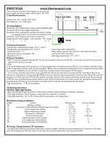
Figure 1.1 — Series F4P Inputs and Outputs (Standard, 1 input, F4P _ - _ _ AA - _ _ _ _; and Enhanced, 3 inputs, F4P _ -
_ _ AB - _ _ _ _ ).
2 Control Outputs
2 Alarm Outputs
2 Retransmit Outputs
(optional)
F
4
1
2
ˆ
1B
1B
1A
1A
…Alarm1 Lo Deviation
Adjusts Value
Back Next
–1
F
1 or 3 Universal Analog Inputs
1 Communication Input/Output
4 Digital Inputs
å
Watlow’s Series F4P, 96mm by 96mm (1/4 DIN)
Temperature/Process controllers are easy to set up, pro-
gram and operate in the most demanding applications.
The F4P Temperature/Process controller includes:
• four-line, high resolution LCD display;
• guided setup software;
• context-sensitive information key;
• 16-bit microprocessor;
• universal and digital inputs.

1.2 ■ Introduction Watlow Series F4P
Setup Steps
The
ˆˆ
Key
During all these steps, the Information Key will summon
helpful definitions and setup tips. Just position the cur-
sor next to the item you want to know more about, then
press the key. Press it again to return to your task.
See Chapter 3, Operations Page.
4
Establish a set point for static set point
control.
See Chapter 3, Operations Page.
3
Tune the system and set alarm set points.
Learn to navigate the software in Chapter 2,
Operating from the Front Panel, and then go to
Chapter 4, Setup Page. For background, you may
also want to refer to Chapter 7, Features. (This
step may not be necessary if the Series F4P is
already installed in the equipment.)
2
Configure the controller to suit your
application.
See Chapter 8, Installation and Wiring. (This
step will not be necessary if the Series F4P is
already installed in equipment.)
1
Install and wire the controller.
How to do itWhat to do
Your Series F4P may arrive as an independent unit or
already installed in other equipment. The steps below
may or may not apply to all units. The Series F4P soft-
ware can be locked with different types of security. See
Chapter 5, Factory Page.

Watlow Series F4P Operating from the Front Panel ■ 2.1
Chapter Two: Navigation and
Operating from the Front Panel
Displays and Indicator Lights . . . . . . . . . . . . . . . . .2.2
Guided Programming . . . . . . . . . . . . . . . . . . . . . . .2.3
Custom Main Page . . . . . . . . . . . . . . . . . . . . . . . . .2.3
Auto and Manual Operation . . . . . . . . . . . . . . . . . .2.3
Troubleshooting Alarms and Errors . . . . . . . . . . . . .2.4
Figure 2.1 — Page Navigation.
Main Page_____
Input 1 Error
Input 2 Error
Input 3 Error
Alarm 1 Condition
Alarm 2 Condition
Tune Status 1
Input 1 Value
In 1 ■■■■
Input 2 Value
Set Point 1
Set Point 2
Digital Set Point
Power 1A
1A% ■■
Power 1B
1B% ■■■
Digital Ins 1234
Active PID Set
Message 1
Message 2
Message 3
>Go to Operations
Go to Setup
Go to Factory
Operations Page
Autotune PID
Edit PID
Alarm Set Point
PID Crossover
Ramp to Set Point
Control Set Points
Setup Page
System
Analog Inputs
Digital Inputs
Control Outputs
Alarm Outputs
Retransmit Outputs
Communications
Custom Main Page
Static Message
Factory Page
Set Lockout
Diagnostic
Test
Calibration
The Main Page presents
error messages, static
messages and the status
of inputs, outputs and
depending on the Custom
Main Page, parameter
settings in the Setup
Page.
Scroll to the bottom of the
Main Page to reach the
other pages.
When you exit the Setup
or Factory Page, the
controller prompts you to
restore the old settings or
save the new ones.
Series F4P software is organized into four sections called
“pages.” The Main Page is the central, default page that
displays status information on the lower display. To get
to the other pages, you must begin in the Main Page.
✔ Note: Access to the software is limited while the con-
troller is autotuning (Setup and Factory pages are not
accessible).
2

Keys, Displays and Lights
Figure 2.2 — Series F4P Displays and Indicator Lights.
F
4
1
2
i
1B
1B
1A
1A
Main Page___________
Go to Operations
Go to Setup
Go to Factory
Upper Display
Displays Channel 1 actual
process values during
operation. Displays error
information if errors occur.
Communications Status
Light
Blinks when the controller
sends or receives data.
Alarm Output Status Lights
Lit during an alarm state.
Scroll Bar
Indicates that more informa-
tion exists above or below.
Use Up and Down keys.
Active Output Status Lights
Lit when the corresponding
controller channel output is
active.
Lower Display
Guides setup and operation, displays
status information.
Cursor (>):
Points to the selected
parameter or present value.
Moves via the Up, Down,
Right and Left keys.
Auto/Manual Status Light
(Indicates mode status):
• Lit when in manual mode.
• Blinks for 10 seconds after
key pressed, while user
can change mode.
• Not lit during automatic
mode.
Auto/Manual Key
Press to toggle between auto
(closed-loop) and manual
(open-loop) control.
Information Key
Press for tips and definitions,
press again to return to the
original task.
Left and Right Keys
Press Right key to select the
item to the right of the cursor
(>) and proceed to the next
screen. Press Left key to
move left or exit.
Up and Down Keys
Press to move the cursor (>),
increase or decrease a value
or change a letter in a name.
To Clear an Alarm or Error
In an alarm condition, the alarm
status light will be lit. An alarm
message will appear on the Main
Page if configured to do so. To
silence the alarm, move the cursor
to the alarm message and press the
Right key. A message will confirm
the alarm silencing, and the alarm
status light will turn off.
After correcting the condition that
caused the error or alarm, return to
the error or alarm message on the
Main Page, and press the Right key
again. A message will confirm that
the alarm is unlatched.
2.2 ■ Operating from the Front Panel Watlow Series F4P

Watlow Series F4P Operating from the Front Panel ■ 2.3
Guided Programming
The Series F4P software guides users through most
tasks. To accomplish a task, simply proceed through the
sequence of parameters. For each parameter, choose the
appropriate option or establish the value, then press the
Right key to proceed to the parameter on the next
screen. The task is complete when you return to the ini-
tial menu.
1. Use
> or < to move the cursor to select an item
in a list.
2. Press the Right key
...
3. Enter the value and make a choice.
4. Press
. again.
5. Repeat until you return to the original list.
To change a specific, single parameter, proceed through
the parameter sequence without changing values until
you reach that parameter, then make your change. After
changing the value, you may back out of the sequence by
pressing the Left key or continue on through the
sequence by pressing the Right key. When you exit the
page, you must choose to Save Changes or Restore
Values.
.
.
.
Choose Cycle Time:__
>Variable Burst
Fixed Time
Choose Function:____
>Heat
Cool
Choose to Setup:____
>Control Output 1A
Control Output 2A
Main Page___________
Go to Operations
>Go to Setup
Go to Factory
Custom Main Page
The Main Page shows error messages; input and output
status; and allows access to controller software. You can
customize the Main Page to display chosen information
by going to the Setup Page, Custom Main Page Menu.
(See Chapter 4, Setup Page, for instructions.)
Auto and Manual Operation
The Series F4P controller can function as a static set
point controller (auto mode); or the user can directly
control the outputs (manual mode).
In the static set point mode, the Series F4P can only be
operated in a closed-loop configuration.
The Auto/Manual Indicator Light is on when the con-
troller is in manual mode. To toggle between manual and
auto mode, first press the Auto/Manual key
å , then con-
firm your selection in the lower display. The indicator
light will flash after you press
å until you confirm your
choice or 10 seconds have elapsed. While in manual mode
you can adjust the output power level for process outputs
or turn relay or open collector outputs on or off.
çWARNING: Only authorized and qualified personnel
should change the set point on the controller. Failure to
comply with these recommendations may result in dam-
age to equipment and property and injury to personnel.
Static Set Point Control
When the Series F4P is in static set point mode:
• The Upper Display shows the actual process temper-
ature of input 1.
• The Lower Display shows the default or user-config-
ured Main Page.
To operate the Series F4P as a static set point controller,
select SP1 in the Main Page then use the Up and Down
keys to adjust the set point.
Limits may be placed on the set point in the Set Point
Low Limit and Set Point High Limit parameters (Setup
Page > Analog Input 1).
✔ Note: All control activity stops when you enter the
Setup Page, Analog Input, Digital Input, Control Output,
Alarm Output and Retransmit menus.
✔ Note: See also differential set point and ratio set
point.

2.4 ■ Operating from the Front Panel Watlow Series F4P
• Process value must return to normal by
more than the hysteresis value to be
cleared.
• Configure alarm type, sides, hysteresis,
logic and set points.
• Correct cause of input error.
• Check the alarm output function.
• Alarm latched.
• Alarm output not configured cor-
rectly.
• Analog input(s) in error condi-
tion.
• Input may be in error condition.
• Alarm won’t clear.
(To clear the alarm, correct the
alarm condition. If the alarm
is latched, press
. with the
cursor at the alarm message on
the Main Page.)
• Turn on alarm annunciation.• Alarm annunciation is set to off.
• Exit Diagnostic mode.• Controller in Diagnostic mode.
• Configure alarm type, sides, hysteresis, logic
and set points.
• Alarm output not configured.
• Verify that silencing function is required.
Disable if not required.
• Alarm silencing is enabled.
Alarms
• Alarm won’t occur.
• Return controller to factory for repair.• Serial port of controller is defective.
• Verify or replace serial cable.• Serial cable is open or not wired correctly.
• Check converter box wiring and its docu-
mentation.
• Termination and/or pull up of bus required.
• Check computer communications port set-
tings and verify PC communications.
• Computer communications port incorrectly
set up or defective.
• Converter must be half duplex.
• Check converter box wiring and settings.
• EIA-232 to EIA-485 converter incorrectly
set or wired.
• Verify correct connections and test wiring
paths.
• Communications wiring reversed, shorted
or open.
• Look for a break in the daisy chain.• Unit-to-unit daisy chain disconnected.
• Check Communications Setup Menu and set
to correct baud rate. Be sure it is Modbus
RTU protocol.
• Baud rate parameter incorrectly set or
incorrect protocol. Use Modbus RTU, 8 data
bits, no parity and 1 stop bit.
• Check Communications Setup Menu and set
to correct address.
• Address parameter incorrectly set.
Communications
• Unit will not
communicate.
• Measure power for required level. Check
part number for input power required.
• Check wire size.
• Check for bad connections.
• Input power incorrect.
• Check switches, fuses, breakers, interlocks,
limits, connectors, etc. for energized condi-
tions and proper connection.
• Power to unit off.
• Fuse blown.
• Breaker tripped.
• Safety Interlock door switch, etc., activated.
• Separate system limit control latched.
• Wiring open.
Power
• No displays.
Corrective ActionProbable Cause(s)Indication
Troubleshooting

Watlow Series F4P Operating from the Front Panel ■ 2.5
• Return to factory for evaluation.• Component failure.
Upper [Atod`]
Lower !Timeout x
(x is 1 to 3)
• Repair or replace sensor.
• Reverse sensor wiring connections.
Red lead is usually negative for tc.
• Set analog input to match sensor.
• Check sensor isolation. Inputs 2 and
3 are not isolated from each other.
• Sensor open.
• Sensor wired backwards. Display
decreases as process increases.
• Input type set to wrong sensor.
• Ground loop
Upper [SEnhi]
Lower !Input Sensor x+
(x is 1 to 3)
• Repair or replace sensor.
• Reverse sensor wiring connections.
Red lead is usually negative for tc.
• Set analog input to match sensor.
• Check sensor isolation. Inputs 2 and
3 are not isolated from each other.
• Sensor shorted (RTD).
• Sensor wired backwards. Display
decreases as process increases.
• Input type set to wrong sensor.
• Ground loop
Upper [SEnLo]
Lower !Input Sensor x-
(x is 1 to 3)
• Repair or replace sensor.
• Reverse sensor wiring connections.
Red lead is usually negative for tc.
• Set analog input to match sensor.
• Check sensor isolation. Inputs 2 and
3 are not isolated from each other.
• Sensor open.
• Sensor wired backwards. Display
decreases as process increases.
• Input type set to wrong sensor.
• Ground loop
Upper [A-dhi]
Lower !Input x AtoD+
(x is 1 to 3)
• Repair or replace sensor.
• Reverse sensor wiring connections.
Red lead is usually negative for tc.
• Set analog input to match sensor.
• Check sensor isolation. Inputs 2 and
3 are not isolated from each other.
• Sensor shorted (RTD).
• Sensor wired backwards. Display
decreases as process increases.
• Input type set to wrong sensor.
• Ground loop
Upper [A-dLO]
Lower !Input x AtoD
(x is 1 to 3)
Input Errors
(Upper Display shows error code
for input 1 only. Lower Display
shows additional errors. Input
2 and 3 error messages appear
in Lower Display. Alarm
Output Indicator is lit.)
• Tune PID set.
• Check power limit settings.
• Replace fuse or reset circuit breaker.
• Reposition sensor to accurately mea-
sure process.
• Check slidewire settings.
• PID values set incorrectly.
• Power limit set incorrectly.
• Open fuse or circuit breaker on energy
source.
• Incorrect sensor location in the pro-
cess.
• Slidewire (if used) settings incorrect.
• Process will not reach set
point.
• Check operation mode. Automatic is
closed loop, manual is open loop.
• Check power limit settings.
• Check sensor, repair or replace.
• Check outputs, repair or replace.
• Check output settings.
• Check system wiring.
• Controller in manual operation mode
(percent power).
• Power limit set incorrectly.
• Thermocouple shorted.
• Shorted power switching device.
• Output set incorrectly (heat vs. cool).
• System wired incorrectly.
• Process runs away (too high or
too low).
• Check power limit settings.
• Tune PID set.
• Use correct PID set.
• Power limit set incorrectly.
• PID values set incorrectly.
• Incorrect PID set active.
Controllability
• Process will not
stabilize.
• Check alarm logic setting and output
wiring.
• Alarm logic setting incorrect or output
wired incorrectly.
• Alarm output action is
reversed.
Corrective ActionProbable Cause(s)Indication

2.6 ■ Operating from the Front Panel Watlow Series F4P
• Add power line filter for input power.
• Return controller to factory for repair.
• Noise on power line.
• Component failure.
• Checksum error in
Cycle device power.
• Press any key. All parameters will de-
fault.
• Module changed.• Module change. Defaults will
occur. Accept with any key.
• Replace incorrect module with re-
transmit module.
• Wrong module in retransmit 2 slot.• Retransmit 2 Module Error!
Only process modules
supported.
• Replace incorrect module with re-
transmit module.
• Wrong module in retransmit 2 slot.• Retransmit 1 Module Error!
Only process modules
supported.
• Check for correct installation of mod-
ule.
• Module not seated correctly in slot.• Verify the module.
• Check for correct installation of mod-
ule.
• Module installed incorrectly or in
wrong slot.
• Module not allowed
• Replace output module.• Output module failure.• Output 1A
• Output 1B
• Output 2A
• Output 2A
• Move module to correct input slot.
• Move module to correct input slot.
• Input module 2 or 3 is in input 1 slot.
• Input module 1 is in input 2 or 3 slot.
• Verify Input 1
• Verify Input 2 or 3
• Replace module or return controller
to factory for repair
• A module has lost its programming ID. • Incorrect ID!
• Contact factory for further informa-
tion and diagnosis.
• Component failure. • Unknown Error!
Record this number. Contact
the factory.
• Add filter to AC power line and verify
unit is power by AC voltage.
• Controller can’t detect zero cross point.
Noise is present on AC power line or
unit is not powered by AC voltage.
• Zero Cross Failure!
Switched to Fixed
Time control.
System Errors
(Upper Display shows error
numbers. Lower Display mes-
sages indicate cause and
action to take.)
• Check wiring and process valve for
compatibility.
• Process valve is wired incorrectly or in-
compatible.
Upper
Lower Slidewire time out
• Increase slidewire time out value.
• Replace process valve.
• Increase slidewire time out value.
• Check wiring and process valve for
compatibility.
• Slidewire time out value set too short.
• Slidewire valve is stuck or not
responding.
• Process valve is wired incorrectly or in-
compatible.
Upper
Lower Slidewire time out
• Return to factory for evaluation.• Component failure.
Upper
Lower !Input x Error
(x is 1 to 3)
Corrective ActionProbable Cause(s)Indication

Watlow Series F4P Operating from the Front Panel ■ 2.7
• Repair heating/cooling circuits.
• Check circuit breakers, switches,
heater elements, compressor.
• Heater/cooling non-functional.
• Replace sensor.• Sensor shorted.
• Replace relay.• Output relay open or shorted.
• Place sensor near source.• Sensor not properly located
• Check all wiring and components.
• Turn the controller off, then on again.
Open Loop Detect
(Upper Display shows error
code for input 1 only. Lower
Display shows additional
errors.
Upper: [oPLP`]
Lower: Open Loop
• Return controller to factory for repair.• Controller has failed.• Flash memory Failed.
Return controller to the
Factory.
• Return controller to factory for repair.• Controller has failed.• RAM Test Failed!
Return controller to the
Factory.
• Turn the controller off, then on again.
If problem persists, power line filter is
required.
• Power line noise has corrupted memory.• Checksum Error!
Parameter memory.
• Checksum Error!
Unit Config memory
• Checksum Error!
Profile memory.
• Normal operation following flash up-
date of firmware.
• Controller firmware has been updated.• Firmware change.
Parameters are initializing.
• Return controller to factory for repair.• Power was interrupted during a flash
update or there is a component failure.
• Flash Memory Failed!
Return controller to the
Factory.
• Return controller to factory for repair.• Component failure.• RAM Test Failed!
Return controller to the
Factory.
• Should not appear in the field. Call
the factory if you get this message.
• Controller powered up for the first time.• First power-up.
Parameters are initializing.
• This is normal upon module change.• Input or output module was changed.• Module change.
All parameters are initializing.
Corrective ActionProbable Cause(s)Indication

2.8 ■ Operating from the Front Panel Watlow Series F4P
Notes:

Watlow Series F4P Operations Page ■ 3.1
Chapter Three: Operations Page
Alarm Set Points . . . . . . . . . . . . . . . . . . . . . . . . . . .3.1
Autotune PID . . . . . . . . . . . . . . . . . . . . . . . . . . . . . .3.2
Edit PID . . . . . . . . . . . . . . . . . . . . . . . . . . . . . . . . . .3.2
Multiple PID Sets . . . . . . . . . . . . . . . . . . . . . . . . . . .3.3
Cascade Tuning . . . . . . . . . . . . . . . . . . . . . . . . . . . .3.3
This chapter explains how to establish alarm set points,
autotune and manually tune and establish cascade con-
trol through the Operations Page of the software.
To configure the alarm outputs, go to the Setup Page of
the software (see related information in the Parameters
Chapter).
For the alarm clearing procedure, go to the Troubleshoot-
ing Alarms and Errors table in the Navigation and
Operating from the Front Panel Chapter.
For background information about alarms; proportional,
integral and derivative control; and cascade, see the Fea-
tures Chapter.
Alarm Set Points
The Series F4P includes two alarm outputs, which can be
programmed as process, deviation or rate alarms.
Process alarms notify the operator when process values
exceed or fall below Alarm Low and Alarm High Set
Points. Deviation alarms notify the operator when the
process has deviated from the set point beyond the devia-
tion limits. Rate alarms are triggered by a change in
temperature or process value that is faster than the se-
lected rate.
For more information, see the Features Chapter. To set
up the alarms, see the Setup Chapter.
Alarm set points are the points at which alarms switch
on or off, depending on the alarm setting. Alarm set
points can be viewed or changed in the Alarm Set Point
Menus (Operations Page).
The Alarm High Set Point defines the high value that,
if exceeded, will trigger an alarm. This value must be
higher than the alarm low set point and lower than the
high limit of the sensor range.
The Alarm Low Set Point defines the low value that, if
exceeded, will trigger an alarm. This value must be lower
than the alarm high set point and higher than the low
limit of the sensor range.
The Alarm Low Deviation defines the deviation value
on the low side of set point at which the alarm will be
triggered.
The Alarm High Deviation defines the deviation value
on the high side of set point at which the alarm will be
triggered.
✔ Note: You may want to set up the alarms with names
that will identify the alarm conditions. See the Setup
Page.
To Clear an Alarm or Error
In an alarm condition, the alarm status light will be lit.
An alarm message will appear on the Main Page if con-
figured to do so. To silence an alarm, the Silencing option
in the Alarm Output menu (Setup Page) must be en-
abled. To silence the alarm, move the cursor to the alarm
message and press the Right key. A message will confirm
the silencing of the alarm, and the alarm status light will
turn off. After correcting the condition that caused the
error or alarm, return to the error or alarm message on
the Main Page, and press the Right key again. A message
will confirm that the alarm is unlatched.
3

3.2 ■ Operations Page Watlow Series F4P
Autotune PID
In autotuning, the controller automatically selects the
PID parameters for optimal control, based on the ther-
mal response of the system. In the Series F4P, five sets of
PID values are available. Default PID values exist for all
PID sets, although these values typically do not provide
optimal control. PID values can be auto-tuned or adjust-
ed manually. When autotuning is complete, the PID val-
ues will be stored in the Edit PID Menu.
Set point changes for remote, ratio and differential con-
trol are ignored until autotuning is complete.
Autotuning Procedure
Autotuning is initiated from the Operation Menu.
1. Before initiating auto-tune, go to the System Menu
(Setup Page), and establish the Autotune Set Point
to a percentage of set point. This percentage is based
on your knowledge of the system and how much
overshoot or undershoot there is likely to be in on-off
control.
Select to display Tune Status in the Custom Main
Page Menu.
2. Go to the Main Page and adjust set point.
3. Go to the Autotune PID Menu (Operations Page) and
choose the PID set in which to store the values. You
must exit back to Main Page with the left arrow. A
message will be displayed on the Main Page during
the autotuning process.
4. When autotuning is complete, the controller will
store the values for optimum control in the specified
PID set.
For additional information about autotuning and propor-
tional, integral and derivative control, see the Features
Chapter.
✔ Note: While the controller is autotuning, only the Op-
eration Page of the software can be entered.
ç
CAUTION: Choose an autotune set point value that will
protect your product from possible damage from overshoot
or undershoot during the autotuning oscillations. If the
product is sensitive, select the autotune set point very
carefully to prevent product damage.
Edit PID
The Edit PID Menu is useful when Auto-tune PID does
not provide adequate control. Each of the PID parame-
ters can be adjusted manually:
Proportional Band: Define a band for PID control, en-
tered in degrees or units. Lower values increase gain,
which reduces droop but can cause oscillation. Increase
the proportional band to eliminate oscillation.
Integral (Reset): Define the integral time in minutes
per repeat; define reset in repeats per minute. Set re-
peats per minute if units are U.S.; minutes per repeat if
units are SI.
Derivative (Rate): Define the derivative (rate) time in
minutes. Large values prevent overshoot but can cause
sluggishness. Decrease if necessary.
Dead Band: Define the dead band in degrees or units.
Heating dead band shifts the set point down. Cooling
dead band shifts the set point up. For more information,
see the Features Chapter.
For background information, see Chapter 7, Features.
Manual Tuning Procedure
1. Apply power to the Series F4P and establish a set
point on the Main Page.
2. Establish Cycle Time in the Control Output Menu
(Setup Page), as required. Typical cycle times are 1.0
second for an SSR and 5.0 seconds for a mechanical
relay. Faster cycle times sometimes achieve the best
system control. However, if a mechanical contactor or
solenoid is switching power to the load, a longer cy-
cle time may be desirable to minimize wear on the
mechanical components. Experiment until the cycle
time is consistent with the desired quality of control.
3. Go to the Edit PID Menu (Operations Page), and
choose the channel and PID set. Establish values for
the PID parameters: Proportional Band, 5; Integral
(Reset), 0; Derivative (Rate), 0; and Autotune, Tune
Off. Tuning begins when you choose a PID set.
4. When the system stabilizes, watch the value of Input
1 on the Main Page. If this value fluctuates, increase
the proportional band setting until it stabilizes. Ad-
just the proportional band in 3° to 5° increments, al-
lowing time for the system to stabilize between ad-
justments.
5. When Input 1 has stabilized, watch the percent pow-
er on the Main Page. It should be stable, ±2%. At
this point, the process temperature should also be
stable, but it will exhibit droop (stabilized below set
point). The droop can be eliminated with integral (re-
set).

Watlow Series F4P Operations Page ■ 3.3
6. Start with an integral setting of 99.9 minutes and al-
low 10 minutes for the process temperature to get to
set point. If it has not, decrease the setting by half
and wait another 10 minutes. Then halve the setting
again and wait another 10 minutes until the process
value equals the set point. If the process becomes un-
stable, the integral value is too small. Increase it un-
til the process stabilizes.
7. Increase Derivative/Rate to 0.10 minute. Then in-
crease the set point by 11° to 17°C. Watch the sys-
tem's approach to the set point. If the process value
overshoots the set point, increase Derivative/Rate to
0.50 minute.
Increase the set point by 11° to 17°C and watch the
approach to the new set point. If you increase
Derivative/Rate too much, the approach to the set
point will be very sluggish. Repeat as necessary until
the system rises to the new set point without over-
shoot or sluggishness.
For additional information about the burst fire feature,
manual tuning and PID control, see the Features Chapter.
Multiple PID Sets
Environmental chambers, ovens and furnaces typically
have different thermal requirements at high and low
temperatures or pressures. To accommodate this, the Se-
ries F4P can store five different PID sets.
Multiple Tuning Procedure
To autotune multiple PID sets, follow the Autotuning
procedure above for each PID set. When autotuning is
finished for one set, proceed with another.
Cascade
Cascade control is available on enhanced (F4P _ - _ _ AB
- _ _ _ _) Series F4P controllers. For background informa-
tion about cascade control, see the Features Chapter.
Select cascade control through the Analog Input 3 Menu
(Setup Page), and choose Process Cascade or Deviation
Cascade. To set the range for the inner loop set point,
Process Cascade uses Low and High Range settings that
are independent of set point; Deviation Cascade uses De-
viation Low and High settings that are deviations from
the primary set point.
When tuning a cascade system, the inner loop must be
tuned first. The inner loop comprises outputs 1A and 1B
and the Analog Input 1 sensor, which usually measures
the energy source temperature. The output device con-
trols a power switching device, which in turn switches
the heating and cooling. The set point for the inner loop
is generated by the outer loop. For Process Cascade, this
will have a range between the Cascade Low Range and
Cascade High Range.
Cascade Setup Procedure
1. First, configure Analog Input 3, Cascade Low Range
and Cascade High Range.
Go to the Analog Input 3 Menu (Setup Page). Choose
Process or Deviation Cascade. Deviation Cascade refer-
ences Channel 1 set point allowing a range above and
below the current control set point. For Process Cascade
control of a heat/cool or cool only system, set the Cascade
Low Range to a value slightly lower than the lowest
temperature desired in the chamber. For heat-only sys-
tems, set the Cascade Low Range to a value slightly low-
er than the ambient temperature; otherwise the heat
output will never turn fully off.
For heat/cool or heat only systems , set the Cascade
High Range to a value slightly higher than the highest
temperature desired in the chamber. For cool-only
systems, set the Cascade High Range to a value slightly
higher than the ambient temperature; otherwise the
cooling will never fully turn off.
2. Next, configure the controller to tune and display data
for the outer loop. To view Inner Loop Set Point in the
upper display, go to the Setup Page, Custom Main Page
Menu, select the Inner Set point as one of the parame-
ters, P1 to P16, to be displayed in the Main Page.
To also view Analog Input 3 in the upper display, go to
the Setup Page, Process Display Menu, and choose Al-
ternating. Under Set Display Time, choose a duration
for the display of the Input 1 and Input 3 variables.
Cascade Autotuning Procedure
1. Go to Setup Page, Custom Main Page Menu. Choose
Tune Status 1 and Tune Status 2 to appear as 2 of the
16 parameters that can be displayed on the Main Page.
The Main Page will now display the status of the auto-
tuning process.
2. Autotune the inner loop. Go to the Autotune PID Menu
(Operations Page), and select Cascade Inner-loop.
Choose Cascade Inner Loop PID Set 1 to 5, where PID
values will be stored after autotuning. Autotuning be-
gins when you choose the PID set. While autotuning,
the F4 controller will control the energy source in an
on-off mode to a temperature equal to the Cascade High
Range setting x Channel 1 Autotune Set Point. For best
results, use proportional control only on the inner loop.

3.4 ■ Operations Page Watlow Series F4P
3. Next, autotune the outer loop. Go to the Autotune PID
Menu (Operations Page). Choose Cascade Outer Loop,
then choose Outer Loop PID set 1 to 5, where PID val-
ues will be stored after autotuning. Autotuning begins
when you choose the PID set. While autotuning, the
outer loop will be controlled in an on-off mode at a set
point equal to static set point x Ch 1 Autotune Set
Point. In most cases, the autotuning feature will tune
for acceptable control. If not, manually tune the outer
loop (step 4 below). Before manually tuning, record the
values generated by the autotuning feature.
4. To manually tune the outer loop, go to the Edit PID
Menu (Operations Page). Choose Cascade Outer Loop,
then choose Outer Loop PID set 1 to 5. Begin manual
tuning by setting the Proportional Band to 5, Integral
(Reset) to 0, and Rate to 0. Establish the desired set
point and let the system stabilize. When the system
stabilizes, watch the Inner Loop Set Point on the Main
Page. If this value fluctuates, increase the proportional
band until it stabilizes. Adjust the proportional band
in 3° to 5° increments, allowing time for the system to
stabilize between adjustments.
5. When Input 1 has stabilized, watch the percent power
on the Main Page. It should be stable, ±2%. At this
point, the process temperature should also be stable,
but it will exhibit droop (stabilized below set point).
The droop can be eliminated with Integral (reset).
6. Start with an integral setting of 99.9 minutes, and al-
low 10 minutes for the process temperature to come up
to set point. If it has not, decrease the setting by half
and wait another 10 minutes. Then halve the setting
again and wait another 10 minutes until the process
value equals the set point. If the process becomes
unstable, the integral value is too small. Increase it
until the process stabilizes.

Watlow Series F4P Setup Page ■ 4.1
Chapter Four: Setup Page
Parameter Setup Order . . . . . . . . . . . . . . . . . . . . . .4.1
Customizing the Main Page . . . . . . . . . . . . . . . . . .4.2
Static Messages . . . . . . . . . . . . . . . . . . . . . . . . . . .4.2
4
This chapter explains how to configure the controller
software through the Setup Page menus. Setup Page pa-
rameters affect the way the controller responds to your
application, which parameters and functions are visible
in other pages, and the way information is displayed on
the Main Page. Set up the controller properly to provide
a sound foundation for settings in other pages.
For ranges, defaults and other information about specific
parameters, see the Parameters Chapter. Record your
settings in the Parameter Setup Record, also in that
chapter.
For background information about inputs, outputs,
alarms and other features, see the Features Chapter.
Parameter Setup Order
Initial configuration of the Series F4P is best done in the
following order:
1. Go to the System Menu (Setup Page) to configure:
• PID units — SI (Integral, Derivative) or U.S. (Re-
set, Rate);
• Celsius or Fahrenheit scales;
• display of units in the controller’s upper display;
• Autotune set point;
• open-loop detection warnings; and
• controller response to a power outage.
2. Go to other menus on the Setup Page to configure:
• Analog Input x (1 to 3);
• Digital Input x (1 to 4);
• Control Output x (1A, 1B);
• Alarm Output x (1 or 2);
• Retransmit Output x (1 or 2);
• Communications; and
• Custom Main Page and Custom Messages.
3. Go to the Operations Page to tune the PID sets.
4. Go to the Operations Page to set the alarm set
points.
After this initial configuration, the most frequent
changes will be to the Operations Page (alarm set points
and PID sets).
If the Series F4P is already installed in an environmen-
tal chamber, oven, furnace or other equipment, most pa-
rameters will already be configured and access to the
Setup Page may be limited (see Chapter 5, Factory
Page).
Changing Setup Page parameters may change other pa-
rameters. In some cases, a change in one parameter will
affect the defaults of others. To see how all the pages,
menus and parameters are grouped, see the software
map on the inside back cover of this manual.
✔ Note: For more information about how parameter set-
tings affect the controller’s operation, see the Features
Chapter.
çWARNING: Only authorized and qualified personnel
should change the factory-default settings, which may
cause changes in other settings. Failure to comply with
this recommendation may result in damage to equipment
and property and injury to personnel.

4.2 ■ Setup Page Watlow Series F4P
Customizing the Main Page
Up to 16 lines can be added to the Main Page to display
status and information from the controller.
Go to the Custom Main Page Menu on the Setup Page.
The first screen will prompt you to choose one of the 16
lines to customize. "P1 Parameter" is the first line; "P16
Parameter" is the 16th. After choosing this line by press-
ing ., select a parameter to monitor.
Your choices are listed under Custom Main Page in the
Setup Page Parameter Table in this chapter.
Figure 4.2 — Example of Parameters on the Custom Main
Page.
Input1 26°C
PID Set 1
Power1A 0%
Power1B 55%
DigitalIn _234
Choose P:1 Display_ _
>None
Input 1 Value ■
Input 1 Value bar ▼
Choose:_ _ _____
>P1 Parameter
P2 Parameter ■
P3 Parameter ▼
Static Messages
Digital inputs can be configured to display a message
that the user enters. The message is displayed on the
Main Page when the digital input is active.
This feature could, for instance, display “DOOR OPEN” if
an oven door is not closed all the way.
/