
INSTALL:
4x
INSTALL:
4x
INSTALL:
4x
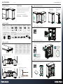
INSTALL THE ITX MOTHERBOARD WITH 4x MOTHERBOARD SCREWS
Plug in all cables you need for
your build into the power
supply rst before installing it
for easier installation
The right-side panel can be
secured with a screw if cables
are pushing against it.
CLEARANCE REAR
SIDEFRONT
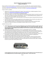
INSTRUCTION MANUAL
Thank you for choosing Phanteks. Please take a moment to
carefully go through the manual. Phanteks will not take
responsibility for any damages incurred due to incorrect
installation or usage of this product.
This manual supports the following models:
PH-EC200AC_BK (2x 120 mm Black Fans)
PH-EC200ATG_DBK (2x 120 mm D-RGB Fans)
INTRODUCTION
PRODUCT OVERVIEW
ECLIPSE P200A
INSTRUCTION MANUAL V1.0V1.0
English
1. Power Button
2. Reset Button
(P200AC Only)
3. D-RGB Mode
(P200ATG-D Only)
4. D-RGB Color
(P200ATG-D only)
5. Headphone / Microphone
6. USB-C Gen 2
(P200ATG-D only)
7. USB 3.0
Francais
1. Bouton d’alimentation
2. Bouton de réinitialisation
(P200AC Only)
3. D-RGB Mode
(P200ATG-D Only)
4. D-RGB Color
(P200ATG-D Only)
5. Casque / Microphone
6. USB-C Gen 2
(P200ATG-D only)
7. USB 3.0
Deutch
1. Ein-/Aus Schalter
2. Reset-Knopf
(P200AC Only)
3. D-RGB Mode
(P200ATG-D Only)
4. D-RGB Color
(P200ATG-D Only)
5. Kopfhörer / Mikrofon
6. USB-C Gen 2
(P200ATG-D only)
7. USB 3.0
Espanol
1. Botón de encendido
2. Botón de reinicio
(P200AC Only)
3. D-RGB Mode
(P200ATG-D Only)
4. D-RGB Color
(P200ATG-D Only)
5. Auricular / Micrófono
6. USB-C Gen 2
(P200ATG-D only)
7. USB 3.0
ECLIPSE P200A Performance (PH-EC200AC_BK)
ECLIPSE P200A DIGITAL-RGB (PH-EC200ATG_DBK)
FRONT I/O FEATURES
STEP 2.
MOTHERBOARD INSTALLATION
THE POWER SUPPLY IS INSTALLED THROUGH THE REAR OF THE CHASSIS. LOOSEN THUMBSCREWS TO REMOVE PSU BRACKET.
INSTALL PSU TO BRACKET WITH 4x PSU SCREWS.
STEP 3.
POWER SUPPLY INSTALLATION
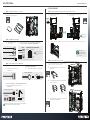
INSTALL THE SSD(s) WITH 4x SSD SCREWS ON THE DEDICATED
SSD BRACKET AND MOUNT IT BACK INTO THE CHASSIS.
STEP 4.
STORAGE INSTALLATION - Dedicated 2.5” SSD Bracket
STEP 1.
REMOVING CHASSIS PANELS
a. PULL THE SIDE PANEL, THEN LIFT THE PANEL UP
TO REMOVE IT
b. REMOVE FRONT PANEL
BY PULLING ON THE
PANEL FROM BELOW
c. REMOVE THE BOTTOM
DUST FILTER FROM
THE FRONT
120
FAN
120
RAD
5 7643
1
120
FAN
120
RAD
120
FAN
140
FAN
BOTTOM
120
FAN
120
RAD
140
RAD
CPU Cooler Height 165 mm
GPU Clearance 355 mm
GPU Thickness 3-slot, 65mm
5 76*2
1
LOOSEN:
2x
P200A PRE-INSTALLED ACCESSORIES:
P200A INCLUDED ACCESSORIES:
2x 120 mm Black or
2x 120 mm D-RGB
4x PSU Screw 3x Case Screw 1x Thumb Screw6x Zip Ties2x SSD Cover 1x Vertical GPU Mount21x Motherboard
+ SSD Screw
COLO RS
2 SEC
MODE S
SOLID
BREAT HING
RADA R
SPARKL E
RAINBOW
PRESS AND HOLD THE MODE BUT TO N TO TURN OFF LED S
PRESS AGAIN TO TURN ON
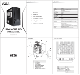
DIGITAL-RGB CONTROLS (P200ATG_D MODEL)
1
2
1
2
*Optional upgrade

For a more accurate overview,
please consult the motherboards’
manual.
POWER LED
POWER SWITCH
NOT USED
HDD LED
RESET SWITCH
Power LED*
a. CONNECT THE HD-AUDIO &
USB 3.0 CABLES
b. CONNECT THE FRONT I/O CABLES TO THE FRONT I/O HEADER ON THE
MOTHERBOARD SEE FRONT I/O HEADER DIAGRAM FOR GENERAL REFERENCE
ALL MODELS:
MOTHERBOARD FRONT I/O HEADER DIAGRAM
P200AC MODEL ONLY:
P200ATG_D MODEL ONLY:
SATA
a. CONNECT THE SATA CABLE TO THE
POWER SUPPLY
CONNECT MORE DRGB PRODUCTS
b. CONNECT DRGB CONNECTOR TO DRGB PRODUCTS
c. CONNECT MOTHERBOARD DRGB ADAPTER TO THE
MOTHERBOARD
SYNC YOUR CASE LIGHTING TO THE MOTHERBOARD OPTIONAL
To DIGITAL-RGB Products
MOTHERBOARD
D-RGB H EADER
To D-RGB Motherboard (optional)
Compatible with:
INSTALL:
3x
ECLIPSE P200A
INSTRUCTION MANUAL V1.0
OPTIONAL UPGRADES
INSTALL:
4x
a. INSTALL THE HDD DRIVE INTO THE STACKABLE 3.5”
HDD BRACKET.
b. STACK TWO BRACKETS WHEN INSTALLING MORE HDDs.
IF NOT, SKIP THIS STEP.
T O REMOVE A BRACKET,
PRESS AND PULL TO RELEASE.
d. MOUNT THE BRACKETS INTO THE CHASSIS AND SECURE
EACH HDD WITH 2 THUMBSCREWS
STEP 8.
STORAGE INSTALLATION - 3.5” HDD
STEP 5.
a. Release the GPU brackets by
removing 3 screws.
b. Secure the GPU brackets as shown with
the same 3 screws.
c. Secure the GPU Mount to the bottom of the chassis with the 2 thumb screws. Secure the Riser Cable to the GPU Mount.
STEP 7.
VERTICAL GPU MOUNT - OPTIONAL
MOTHERBOARD CONNECTIONS
STEP 6.
DRGB LIGHTING P200ATG_D MODEL ONLY
(RISER CABLE SOLD SEPERATELY. PH-CBRS_FL15)
(STACKABLE HDD BRACKET SOLD SEPERATELY. PH-HDDKT_03)
HD D
1
2
The GPU Mount has two
mounting positions. Position A
allows for better air cooling and
3-slot GPU cards.
INSTALL:
2x
USB-C
RAINBOW
ADDRESSABLE ADDRESSABLE
INSTALL:
4x
INSTALL THE SSD DRIVE WITH 4x SSD SCREWS ON THE SSD COVER
AND MOUNT BACK INTO THE CHASSIS.
Up to 4 Stackable HDD Brackets can be installed in the side
fan locations. These are available separately.
STEP 5.
STORAGE INSTALLATION - 2.5” SSD Covers
1
2
RELEASE:
3x
B
A
Lighting must be controlled through the motherboard software when connected to the motherboard.
The Color and Mode buttons do not work when synced to motherboard.
The rear fan position
cannot be used with a
vertical GPU.
*On the P200ATG_D model, the D-RGB lighting functions as a power LED.
-
 1
1
-
 2
2


Phanteks Eclipse P200A Performance Edition Owner's manual
- Type
- Owner's manual
- This manual is also suitable for
Ask a question and I''ll find the answer in the document
Finding information in a document is now easier with AI
Related papers
-
Phanteks Glacier G30 Aorus Block and Backplate Owner's manual
-
-
-
-
-
-
-
-
-
Phanteks G3090Ti GLACIER MSI BACKPLATE Installation guide
Other documents
-
 Inteset INT-TX482-1U Assembly Instructions
-
 AZZA LUMINOUS 110 User manual
-
Genesis Irid 400 RGB Quick Installation Manual
-
Eclipse P400 User manual
-
 Riotoro CR500 User manual
-
Asus ROG STRIX B450-F GAMING User manual
-
MSI MEG Z590 GODLIKE Owner's manual
-
-
Rosewill PRISM S White ATX Mid Tower User manual
-
MSI MAG B560M MORTAR WIFI Owner's manual


