Page is loading ...

Chore-Tronics
®
2 Control (Breeder Edition)
Installation & Operator’s Instruction Manual
MT1912AAugust 2006

Chore-Time Warranty Chore-Tronics® 2 Control (Breeder Edition)
2
MT1912A
Chore-Time Equipment (“Chore-Time”) warrants each new Chore-Time product manufactured by it to be free
from defects in material or workmanship for one year from and after the date of initial installation by or for the
original purchaser. If such a defect is found by the Manufacturer to exist within the one-year period, the
Manufacturer will, at its option, (a) repair or replace such product free of charge, F.O.B. the factory of
manufacture, or (b) refund to the original purchaser the original purchase price, in lieu of such repair or
replacement. Labor costs associated with the replacement or repair of the product are not covered by the
Manufacturer.
Conditions and Limitations
1. The product must be installed by and operated in accordance with the instructions published by the
Manufacturer or Warranty will be void.
2. Warranty is void if all components of the system are not original equipment supplied by the Manufacturer.
3. This product must be purchased from and installed by an authorized distributor or certified representative
thereof or the Warranty will be void.
4. Malfunctions or failure resulting from misuse, abuse, negligence, alteration, accident, or lack of proper
maintenance, or from lightning strikes, electrical power surges or interruption of electricity, shall not be
considered defects under the Warranty.
5. This Warranty applies only to systems for the care of poultry and livestock. Other applications in industry
or commerce are not covered by this Warranty.
The Manufacturer shall not be liable for any Consequential or Special Damage which any purchaser may suffer
or claim to suffer as a result of any defect in the product. “Consequential” or “Special Damages” as used herein
include, but are not limited to, lost or damaged products or goods, costs of transportation, lost sales, lost orders,
lost income, increased overhead, labor and incidental costs and operational inefficiencies.
THIS WARRANTY CONSTITUTES THE MANUFACTURER’S ENTIRE AND SOLE WARRANTY AND
THIS MANUFACTURER EXPRESSLY DISCLAIMS ANY AND ALL OTHER WARRANTIES,
INCLUDING, BUT NOT LIMITED TO, EXPRESS AND IMPLIED WARRANTIES AS TO
MERCHANTABILITY, FITNESS FOR PARTICULAR PURPOSES SOLD AND DESCRIPTION OR
QUALITY OF THE PRODUCT FURNISHED HEREUNDER.
Chore-Time Distributors are not authorized to modify or extend the terms and conditions of this Warranty in any
manner or to offer or grant any other warranties for Chore-Time products in addition to those terms expressly
stated above. An officer of CTB, Inc. must authorize any exceptions to this Warranty in writing. The Manufacturer
reserves the right to change models and specifications at any time without notice or obligation to improve previous
models.
Effective: September 2006
Chore-Time Equipment
A Division of CTB, Inc.
P.O. Box 2000 • Milford, Indiana 46542-2000 • U.S.A.
Phone (574) 658-4101 • Fax (877) 730-8825
Email: [email protected] • Internet: http//www.ctbinc.com
Thank You
The employees of Chore-Time Equipment would like to thank your for your recent Chore-Time purchase. If a
problem should arise, your Chore-Time distributor can supply the necessary information to help you.
Chore-Time Warranty

Contents
Topic Page
MT1912A
* Legend: C = Customer (end user), D = Distributor (sales), I = Installer of equipment
3
Chore-Time Warranty . . . . . . . . . . . . . . . . . . . . . . . . . . . . . . . . . . . . . . . . . . . . . . . . 2
General. . . . . . . . . . . . . . . . . . . . . . . . . . . . . . . . . . . . . . . . . . . . . . . . . . . . . . . . . . . . . 5
Support Information. . . . . . . . . . . . . . . . . . . . . . . . . . . . . . . . . . . . . . . . . . . . . . . . . . . . . . . . . . 5
Safety Information . . . . . . . . . . . . . . . . . . . . . . . . . . . . . . . . . . . . . . . . . . . . . . . . . . . 5
Follow Safety Instructions. . . . . . . . . . . . . . . . . . . . . . . . . . . . . . . . . . . . . . . . . . . . . . . . . . . . . 5
Decal Descriptions. . . . . . . . . . . . . . . . . . . . . . . . . . . . . . . . . . . . . . . . . . . . . . . . . . . . . . . . . . . 5
Introduction to the Control . . . . . . . . . . . . . . . . . . . . . . . . . . . . . . . . . . . . . . . . . . . . 6
Description of Control Front Panel . . . . . . . . . . . . . . . . . . . . . . . . . . . . . . . . . . . . . . . . . . . . . . 6
Display Screen . . . . . . . . . . . . . . . . . . . . . . . . . . . . . . . . . . . . . . . . . . . . . . . . . . . . . . . . . . . . . . 6
Navigation Keys. . . . . . . . . . . . . . . . . . . . . . . . . . . . . . . . . . . . . . . . . . . . . . . . . . . . . . . . . . . . . 7
Index Keys . . . . . . . . . . . . . . . . . . . . . . . . . . . . . . . . . . . . . . . . . . . . . . . . . . . . . . . . . . . . . . . . . 9
How to Maneuver in the Viewing Screen . . . . . . . . . . . . . . . . . . . . . . . . . . . . . . . . . . . . . . . . . 11
Entering Time and Date using the Numeric Keypad. . . . . . . . . . . . . . . . . . . . . . . . . . . . . . . . . 13
Relay Box Indication Lights and Auto/Manual Switches . . . . . . . . . . . . . . . . . . . . . . . . . . . . . 14
Glossary of Terms. . . . . . . . . . . . . . . . . . . . . . . . . . . . . . . . . . . . . . . . . . . . . . . . . . . . 15
Overview of Screens . . . . . . . . . . . . . . . . . . . . . . . . . . . . . . . . . . . . . . . . . . . . . . . . . . 19
Screen 1: Current Conditions. . . . . . . . . . . . . . . . . . . . . . . . . . . . . . . . . . . . . . . . . . . . . . . . . . . 19
Screen 2: Auxiliary Data . . . . . . . . . . . . . . . . . . . . . . . . . . . . . . . . . . . . . . . . . . . . . . . . . . . . . . 20
Screen 3: Set Temp/Min Timer . . . . . . . . . . . . . . . . . . . . . . . . . . . . . . . . . . . . . . . . . . . . . . . . . 22
Screen 5: Clocks. . . . . . . . . . . . . . . . . . . . . . . . . . . . . . . . . . . . . . . . . . . . . . . . . . . . . . . . . . . . . 26
Screen 6: History-Production. . . . . . . . . . . . . . . . . . . . . . . . . . . . . . . . . . . . . . . . . . . . . . . . . . . 31
Screen 7: History-Environment . . . . . . . . . . . . . . . . . . . . . . . . . . . . . . . . . . . . . . . . . . . . . . . . . 34
Screen 8: Alarms . . . . . . . . . . . . . . . . . . . . . . . . . . . . . . . . . . . . . . . . . . . . . . . . . . . . . . . . . . . . 36
Screen 9: Curve Settings . . . . . . . . . . . . . . . . . . . . . . . . . . . . . . . . . . . . . . . . . . . . . . . . . . . . . . 38
Screen 10: Management Screen. . . . . . . . . . . . . . . . . . . . . . . . . . . . . . . . . . . . . . . . . . . . . . . . . 40
Screen 11: Static Pressure . . . . . . . . . . . . . . . . . . . . . . . . . . . . . . . . . . . . . . . . . . . . . . . . . . . . . 43
Screen 12: Programs . . . . . . . . . . . . . . . . . . . . . . . . . . . . . . . . . . . . . . . . . . . . . . . . . . . . . . . . . 44
Setup Screens (Screens 13 & 14) and Initial Setup . . . . . . . . . . . . . . . . . . . . . . . . . . . . . . . . . . 48
Screen 13: Setup-Genera . . . . . . . . . . . . . . . . . . . . . . . . . . . . . . . . . . . . . . . . . . . . . . . . . . . . . .l 48
Screen 14: Setup-Control. . . . . . . . . . . . . . . . . . . . . . . . . . . . . . . . . . . . . . . . . . . . . . . . . . . . . . 53
Control Operation Overview. . . . . . . . . . . . . . . . . . . . . . . . . . . . . . . . . . . . . . . . . . . 59
Standard Mode Functionality. . . . . . . . . . . . . . . . . . . . . . . . . . . . . . . . . . . . . . . . . . . . . . . . . . . 59
Mode Transitions . . . . . . . . . . . . . . . . . . . . . . . . . . . . . . . . . . . . . . . . . . . . . . . . . . . . . . . . . . . . 60
Control Installation . . . . . . . . . . . . . . . . . . . . . . . . . . . . . . . . . . . . . . . . . . . . . . . . . . 69
Mounting the Control. . . . . . . . . . . . . . . . . . . . . . . . . . . . . . . . . . . . . . . . . . . . . . . . . . . . . . . . . 69
Wiring the Control . . . . . . . . . . . . . . . . . . . . . . . . . . . . . . . . . . . . . . . . . . . . . . . . . . . . . . . . . . . 73
Analog Inputs. . . . . . . . . . . . . . . . . . . . . . . . . . . . . . . . . . . . . . . . . . . . . . . . . . . . . . . . . . . . . . . 75
Remote Light Dimmer Control Wiring . . . . . . . . . . . . . . . . . . . . . . . . . . . . . . . . . . . . . . . . . . . 85
Starting the Control . . . . . . . . . . . . . . . . . . . . . . . . . . . . . . . . . . . . . . . . . . . . . . . . . . . . . . . . . . 89
Testing the Back Up Box. . . . . . . . . . . . . . . . . . . . . . . . . . . . . . . . . . . . . . . . . . . . . . . . . . . . . . 91
MS Board Dip Switch Positions . . . . . . . . . . . . . . . . . . . . . . . . . . . . . . . . . . . . . . . . . . . . . . . . 92
PC Connection . . . . . . . . . . . . . . . . . . . . . . . . . . . . . . . . . . . . . . . . . . . . . . . . . . . . . . 93
Troubleshooting . . . . . . . . . . . . . . . . . . . . . . . . . . . . . . . . . . . . . . . . . . . . . . . . . . . . . 94

Contents - continued
Topic Page
4
MT1912A
Programming Trouble Shooting. . . . . . . . . . . . . . . . . . . . . . . . . . . . . . . . . . . . . . . . . . . . . . . . . 94
Equipment and Potentiometer Troubleshooting . . . . . . . . . . . . . . . . . . . . . . . . . . . . . . . . . . . . 97
IONet Error Addr:xx . . . . . . . . . . . . . . . . . . . . . . . . . . . . . . . . . . . . . . . . . . . . . . . . . . . . . . . . 102
Wiring Diagrams . . . . . . . . . . . . . . . . . . . . . . . . . . . . . . . . . . . . . . . . . . . . . . . . . . . 103
Backup Control Wiring (24Vdc) . . . . . . . . . . . . . . . . . . . . . . . . . . . . . . . . . . . . . . . . . . . . . . . 103
Fan Wiring . . . . . . . . . . . . . . . . . . . . . . . . . . . . . . . . . . . . . . . . . . . . . . . . . . . . . . . . . . . . . . . . 104
Linear Lift Wiring Diagram. . . . . . . . . . . . . . . . . . . . . . . . . . . . . . . . . . . . . . . . . . . . . . . . . . . 105
Turbo-Cool™ Wiring. . . . . . . . . . . . . . . . . . . . . . . . . . . . . . . . . . . . . . . . . . . . . . . . . . . . . . . . 106
I/O Board Wiring. . . . . . . . . . . . . . . . . . . . . . . . . . . . . . . . . . . . . . . . . . . . . . . . . . . . . . . . . . . 106
Weight Bin/Feeder Fill Wiring . . . . . . . . . . . . . . . . . . . . . . . . . . . . . . . . . . . . . . . . . . . . . . . . 107
Backup Egg Room Cooler Wiring. . . . . . . . . . . . . . . . . . . . . . . . . . . . . . . . . . . . . . . . . . . . . . 108
Backup Egg Room Humidifier Wiring. . . . . . . . . . . . . . . . . . . . . . . . . . . . . . . . . . . . . . . . . . 109
Brooder Wiring . . . . . . . . . . . . . . . . . . . . . . . . . . . . . . . . . . . . . . . . . . . . . . . . . . . . . . . . . . . . 110
Improving Lightning Surge Suppression. . . . . . . . . . . . . . . . . . . . . . . . . . . . . . . . 111
Itemized Parts . . . . . . . . . . . . . . . . . . . . . . . . . . . . . . . . . . . . . . . . . . . . . . . . . . . . . . 114
Parts Listing . . . . . . . . . . . . . . . . . . . . . . . . . . . . . . . . . . . . . . . . . . . . . . . . . . . . . . . 115
Extra Parts and Kits. . . . . . . . . . . . . . . . . . . . . . . . . . . . . . . . . . . . . . . . . . . . . . . . . 116
Input Wiring Assignment Diagram . . . . . . . . . . . . . . . . . . . . . . . . . . . . . . . . . . . . 118
Technical Specifications. . . . . . . . . . . . . . . . . . . . . . . . . . . . . . . . . . . . . . . . . . . . . . 119

Chore-Tronics® 2 Control (Breeder Edition) General
MT1912A
5
Support Information
The Chore-Tronics
®
2 Controls are used to control the Climate in a structure to insure efficient growth of
Livestock. Using this equipment for any other purpose or in a way not within the operating recommendations
specified in this manual will void the warranty and may cause personal injury.
This manual is designed to provide comprehensive planning, installation, safety, operation, and parts listing
information. The Table of Contents provides a convenient overview of the information in this manual. The Table
of Contents also specifies which pages contain information for the sales personnel, installer, and consumer (end
user).
Caution, Warning and Danger Decals have been placed on the equipment to warn
of potentially dangerous situations. Care should be taken to keep this information
intact and easy to read at all times. Replace missing or damaged safety decals
immediately.
Using the equipment for purposes other than specified in this manual may cause
personal injury and/or damage to the equipment.
Follow Safety Instructions
Carefully read all safety messages in this manual and on your equipment safety signs.
Follow recommended precautions and safe operating practices.
Keep safety signs in good condition. Replace missing or damaged safety signs.
Decal Descriptions
DANGER: Electrical Hazard
Disconnect electrical power before inspecting or servicing equipment unless
maintenance instructions specifically state otherwise.
Ground all electrical equipment for safety.
All electrical wiring must be done by a qualified electrician in accordance with local
and national electric codes.
Ground all non-current carrying metal parts to guard against electrical shock.
With the exception of motor overload protection, electrical disconnects and over
current protection are not supplied with the equipment.
General
Safety Information

Introduction to the Control Chore-Tronics® 2 Control (Breeder Edition)
6
MT1912A
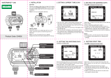
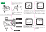
Description of Control Front Panel
Display Screen
The display screen is a ¼ VGA display. This screen will display the requested
information when a Subject Button is pressed. The display screen always remains lit.
When the control is left dormant the Current Conditions screen will be visible. When
assigned relay switches are not in the automatic position, or an alarm condition is
occurring, the CHECK SWITCHES or CHECK ALARMS indication appears,
flashing at the bottom of the screen. (See Figure 2 Below)
Introduction to the Control
Item Description
1
Chore-Tronics
®
2 (Beeder
Edition) Front Panel
2 Display Screen
3 Subject Buttons
4 Navigation Keys
5 Edit Buttons
6 Enter Key
7 Alphanumeric Keypad
8 Index Keys
1
2
Figure 1. Description of Front Panel
3
7
6
5
8
4
MT1842-084 10/04
Figure 2. Display Screen

Chore-Tronics® 2 Control (Breeder Edition) Introduction to the Control
MT1912A
7
Navigation Keys
Navigation Buttons
These buttons allow you to scroll up and down in long screens. Continuously
pressing the up or down arrow button increases the scrolling speed. When you are in
the Edit Mode the left and right arrow keys move the cursor to editable (changeable)
positions. The cursor highlights the areas that can be changed.
Edit Buttons
When the button labeled EDIT is pressed and you are looking at a screen that has
editable fields, the cursor appears. With the Navigation Buttons, you can move the
cursor to the parameter on the screen that you want to edit. By pressing the “+” or “–
” buttons, the numerical values are changed. If you are changing text (i.e. “yes” or
“no”), the "+" and "–" keys scroll through the possible text choices. Pressing the
EDIT button a second time exits the edit mode.
Enter Key
The Enter is used to accept changes made in editable fields. Press Enter key after a
desired change is made to save the change. Alternatively changes can also be
accepted by pressing the down navigation button or by pressing the Edit key and
exiting the edit mode.
EDIT
+
-
MT1842-001 10/04
ENTER
MT1842-002 9/04

Introduction to the Control Chore-Tronics® 2 Control (Breeder Edition)
8
MT1912A
Alphanumeric Keypad
The Alphanumeric Keypad is used to enter a number directly into a field without
having to scroll to the number. To directly enter a number, press the Edit Key and
highlight the desired field to be changed. Next type in the desired value of the field
and either press the Enter Key or press the down navigation arrow. The new value
should now be in place.
The Alphanumeric Keypad can also be used to change the name of some text fields.
To change a text field name press the Edit Key and highlight the desired field to be
changed. (In the example below, Drinker 1 is highlighted). Next, enter the new letters
into the text field by pressing the appropriate number on the Key Pad. (In the example
below we are changing it to read Brood). The first letter above each Key is chosen by
pushing that Key once. To choose the second letter above each Key, push that Key
twice. In our example the letter B is chosen by pressing the #2 button two times in a
row. The letter R is chosen by pressing the #7 button three times in a row. Allow a
pause of 1-2 seconds in between letters.
MT1842-055 10/04
73.0
O
L
I
X
W
Y
Y
T
V
U
Q
P
R
S
N
M
J
K
G
H
D
F
E
ENTER
A
B
C
4
1
78
5
2
9
6
3
.0
UNDO
EDIT
+
-
1) Press the Edit Key and highlight
the number you want to change.
2) Press the desired number on the
Alphanumeric Keyboard.
3) Push the Enter Key or the down
Navigation Arrow.
O
L
I
X
W
Y
Y
T
V
U
Q
P
R
S
N
M
J
K
G
H
D
F
E
ENTER
A
B
C
4
1
78
5
2
9
6
3
.0
UNDO
Figure 3. Alphanumeric Keypad
MT1842-044 10/04
Enter new letters into the field by
pressing the appropriate numbers on
the keypad.
Select Drinker 1
Drinker 1 has been successfully
changed to "Brood".
Figure 4. Changing Text Fields

Chore-Tronics® 2 Control (Breeder Edition) Introduction to the Control
MT1912A
9
Tab Keys
There are six Tab Keys across the bottom of the display. The Tab Keys allow access
to different screens within a given Subject Key. The name of each screen will appear
at the bottom of the display above the Tab Key. To select a screen, press the Tab Key
that is directly below the name of the desired screen. In Figure 5 below, the Tab Key
that is under "Equip. For" has been pressed, accessing the "Equip. For" screen.
Index Keys
The Index keys are used to scroll through the Feed Clock Curve and the Light Clock
Curve bend points and to scroll through certain lists such as heat zone runtimes in the
History-Environment screen. An arrow(s) will appear whenever the Index Keys can
be used to quickly scroll through lists or bend points. In Figure 6 below, there is an
example of using the Index Keys to scroll from HtZone 1 to HtZone 2.]
MT1842-046 10/04
Item Description
1Tab Key
Figure 5. Tab Keys
1
MT1842-047 10/04
Item Description
1Index Keys
2 Index Key Arrows
1
2
MT1842-048 10/04
Heating History HtZone 1
----------------------------------------
DAY Ht Zone 1
7 4:13
6 4:13
5 4:13
4 4:13
3 4:13
2 4:13
1 4:13
00 4:13
Heating History HtZone 2
----------------------------------------
DAY Ht Zone 1
7 4:13
6 4:13
5 4:13
4 4:13
3 4:13
2 4:13
1 4:13
00 4:13
Figure 6. Index Keys
Example: To change from HtZone 1 to HtZone 2, push the Down Index Key.

Introduction to the Control Chore-Tronics® 2 Control (Breeder Edition)
10
MT1912A
Fast Edit
While editing a number on the screen, you will notice that the digit you are
changing is underlined. For example: (72.0
). If you wish you can move to
different digits of the number in order to change the number more rapidly. To do
this See Figure 7 below. Fast Edit is very useful when making large changes to
numbers.
Security
To provide for security in setting your Controls, there is a security feature that
appears when you press the Edit button. The Control automatically asks for an
access code at that time, The access code is a four digit number that you have
selected while setting up the Control and is explained under the “Changing the
Access Code” section of this manual. Once you have inserted the correct code,
the Control allows you to make changes. If five minutes pass since your last
change, the access code has to be re-entered.
Subject Buttons
On the front of the Control are 14 subject keys. As each Subject Button is
pressed, the light beside that button turns on and the subject that is described
beside the button appears on the screen. If no other buttons are pressed for 5
minutes, the Control automatically returns to the Current Conditions screen.
Alarm Indicator (LED)
The Indicator Light (LED) next to the number 8 Subject Button indicates the
current status of the Alarm. The Alarm Status’s are as follows...
1. Solid Green- All is normal (No Alarm)
2. Flashing Green- Warning, un-noticed alarm, or temporary off alarm
3. Flashing Red- Active Alarm
72.0
Press "+" followed by "-"
Within 3 seconds, Press the Left arrow twice
72.0
Press "+" twice arrow
92.0
Mt1701-065 1/02
72.0
Press the Edit button
Action
Result
Figure 7. Fast Edit.

Chore-Tronics® 2 Control (Breeder Edition) Introduction to the Control
MT1912A
11
How to Maneuver in the Viewing Screen
• The procedures below give a brief overview on the use of the Navigation Buttons
and the Edit Buttons.
• Screen 13, Setup-General is used for this example.
Using the Navigation Buttons
1. Press BUTTON 13. Figure 8 appears in the display.
2. Press the DOWN ARROW once.
The view shown on the screen will scroll down one line as shown in Figure
9. If you push the UP ARROW once the text scrolls back to where it was.
3. The left and right arrow keys are used during the Edit Mode.
MT1842-086 10/04
Figure 8. Navigation Buttons.
MT1842-087 10/04
Figure 9. Navigation Buttons-Down Arrow.

Introduction to the Control Chore-Tronics® 2 Control (Breeder Edition)
12
MT1912A
Using the Edit Buttons
The Edit Mode is entered by pressing the Edit Button. Pressing the Edit Button
a second time exits the Edit Mode.
MT1842-064 10/04
1
°F
Figure 10. Setup Screen.
MT1842-061 10/04
1. Press BUTTON 13.
The Setup-General screen appears (Figure
10).
3. Press the (+) or (–) buttons to edit the House #.
The (+) key increases the value and the (–) key
decreases the value.
MT1842-063 10/04
1
CURSOR
2. Press the EDIT button.
This activates the cursor which allows settings
to be edited. Figure 11 shows what the cursor
looks like. If the Control asks you for an "Ac-
cess Code", enter it at this time. See the Screen
13 "General Tab" section of this manual for de-
tails on how to use access code.
4. Press the DOWN ARROW (Figure 12).
Figure 11. Setup-General Screen in Edit Mode.
5. Press the (+) or (–) buttons to change from
Fahrenheit to Celsius.
In this case the (+) and (–) buttons select
different text choices.
6. If two or more editable settings are on the same
line, the left and right arrow buttons are used to
move between those positions.
When a value or text is edited, it is saved in the
memory within a few seconds. If you make a
mistake, change it to what you really want.
Figure 11. Setup-General Screen in Edit Mode.
Figure 12. Press the Down Arrow.

Chore-Tronics® 2 Control (Breeder Edition) Introduction to the Control
MT1912A
13
Entering Time and Date using the Numeric Keypad
You can enter the current Time and Date using the Numeric Keypad.
MT1843-001 3/05
MT1843-002 3/05
8:12 pm
1. Press BUTTON 13.
The Setup-General screen appears (Figure
13).
2. Press the EDIT button and use down arrow to
highlight the Time of day (Figure 14). Using the
Numeric Keypad, enter in the correct hour followed
by the decimal key (.). Enter the correct minutes fol-
lowed by either; am or pm (Use the number 2 on the
Keypad for am, or the number 7 for pm). The exam-
ple below is setting the time to 8:12 pm.
Q
P
R
S
7
1
T
V
U
8
.
A
B
C
2
Hour=8 decimal (.) Minutes=12
then thenthen then then
pm=7
8 8: 8:12
8:12pm
Figure 13. Setup General Screen.
MT1842-061 10/04
Figure 14. Changing Time of Day.
2. Press the EDIT button and use down arrow to
highlight the Date (Figure 15). Using the Numeric
Keypad, enter in the correct day, followed by the
decimal key (.). Then enter the correct month, fol-
lowed by the decimal key (.). Finally, enter the cor-
rect year. The example below is setting the date to
February 7th, 2005.
Q
P
R
S
7
.
A
B
C
2
Day=7
decimal (.)
then then then then
Year=2005
0
.
L
J
K
5
Month =2 decimal (.)
7 7 Feb
7 Feb 2005
7 Feb 2005
Figure 15. Changing the Date.
Use the same procedure to set "Start" and "Stop" times in any of the Clock Screens.

Introduction to the Control Chore-Tronics® 2 Control (Breeder Edition)
14
MT1912A
Relay Box Indication Lights and Auto/Manual Switches
Each Relay Output has its own three position switch that allows the user to select
manual, off or automatic control of each Relay. The Relays and their corresponding
Switches are located in a separate box. Decals are supplied to label each Switch for
the Output function that is assigned to that Switch. The Switches can be placed in
three positions - "on", "off", or "auto". The "auto" position is for normal automatic
operation. Changing a Switch to "on" or "off" overrides "auto" operations. When a
switch that is assigned is placed in a position other than "auto", a message will appear
in the Current Conditions screen advising you to "Check Switches". The light above
each Switch indicates that the Switch's Relay is activated.
Figure 16. Indication Lights and Switches
Item Description
1 Indication Light
2Switch
3Decal
3
2
1

Chore-Tronics® 2 Control (Breeder Edition) Glossary of Terms
MT1912A
15
Analog Input
Analog Inputs can consist of the following:
1. Temperature sensors
2. Static Pressure sensor (0-10 volts)
3. Relative Humidity Sensor (0-10 volts)
4. Potentiometer (Natural Ventilation)
Anticipation
When the control is turning on the fans assigned to the Minimum Ventilation Timer, the control will open the inlets
to the correct position for static pressure control before the fans are turned on. If calculated anticipation is used
(default), the control teaches itself how much adjustment was required during the previous on-off cycle, and uses
that amount of "anticipation" for the next cycle. If the optional fixed anticipation is used, the control will NOT
teach itself what the correct anticipation should be. It uses the amount of "anticipation" that is entered in the Static
Pressure screen (Screen 11). Anticipation will occur when the fans assigned to the Minimum Ventilation Timer
turn on due to the timer reaches an ON cycle or the sensor(s) assigned to the fans reach the fans' ON temperature.
Back Up Relay Output
The backup up relay output is a relay that will be energized as soon as the backup output is assigned to a relay.
This relay will stay energized as long as the control is communicating with the manual switch board where the
output is assigned. The 24 Vdc signal that comes from the control to the back up box should be routed through
this relay. If communication is lost between the main box and the manual switch board, the relay will drop out
allowing the first fan stage in the back up box to turn on. See the Wiring Diagrams section of this manual for more
wiring information.
Bend Point (BP)
The Bend Points (BPs) are simply the points on the curve that define the curve. For the Set Temperature and
Minimum Ventilation Timer curves, the curve values are gradually changed between bend points. The bend point
values are the exact values at midnight beginning the day # of each bend point. The curve takes over when you
turn the curve "on" and the day number is equal to or greater than the day number assigned to BP #1.
Cool Pad Output
The COOL PAD Output is a special function for controlling evaporative cooling that allows you to modulate the
addition of water to the cooling pad in such a way that the usual large temperature swings associated with a cooling
pad are avoided.
Curve
A "curve" is a listing of up to 10 points in time (bend points) that defines how you want a parameter to
automatically vary as the animals age.
Curve Value
The Control will list what the current value(s) the curve would be, if the current day number is greater than the
day # of bend point #1, and the curve is "on", and there is no "offset" to the curve.
Day Number
The intention is that the day # is the age of the animals whose environment is being controlled. Day # 0 does not
exist. Negative days (down to - 7) are allowed. Changing the day # in any screen that shows the day number, will
change the day # in all the other screens that show the day #.
Digital Input
Digital Inputs can consist of the following:
Glossary of Terms

Glossary of Terms Chore-Tronics® 2 Control (Breeder Edition)
16
MT1912A
1. Water meter
2. Feed scale
3. Air speed sensor
4. Low water pressure switch
5. Max feed run time Input
6. PDS flush feed back
Event
This term applies to the time clock Outputs. An "event" is an "on at" time combined
with an "off at" time.
Mode Sensor(s)
The concept of Mode Sensor(s) is essential to the understanding what makes the Control change from one mode
to another. The Mode Sensor(s), of a currently operating mode, determines when the Control will leave that mode.
As an example, while in the Power Mode, the Power Mode Sensor(s) determines when it's too hot to stay in the
Power Mode (i.e. above the tunnel "on" temperature). Because of this, it converts to the Tunnel Mode (assuming
there is no Natural Mode) at the tunnel "on" temperature. It comes back to the Power Mode from the Tunnel Mode,
when the Tunnel Mode Sensor(s) say it's too cold to stay in the Tunnel Mode (i.e. below the tunnel "off"
temperature).
Natural Mode
Natural Mode requires the house to be equipped with Curtains in the side walls that are powered by Drive Units
(Curtain Machines). The Control converts to this mode of operation when the temperature(s) inside the house raise
to a level that the Fans of the Power Mode can't keep the temperature(s) under control. While in the Natural Mode
of operation, the Curtains are opened or closed, as required, to control the temperature(s). This mode of operation
generally happens during moderate weather.
Noticing an Alarm
"Noticing" an alarm is a very important part of using the alarm system. By pressing the alarm button, you can tell
the Control that you have "seen" the alarm message. The first press of the alarm button "notices" the alarm
message at the top of the alarm screen. Each additional press of the alarm button "clears" the first alarm and
"notices" any additional alarm(s), one at a time.
Offset
The term "offset" applies to the Set Temperature and Minimum Ventilation Timer curves only. If you manually
adjust either the Set Temperature or the Minimum Ventilation Timer settings, while the curve is on, you create an
"offset" to that curve relative to it's "curve value". The "curve value" is not changed. (see the "curve value"
definition above.) The curve value is shown as a convenience so that you know what you have to change it back
to in order to get back on the actual curve's table listing. While an "offset" is in effect, the parameter of the curve
is still modified versus time. However, the actual parameter value is the "curve value" modified by the "offset".
Mt1701-Naturalmode 11/01

Chore-Tronics® 2 Control (Breeder Edition) Glossary of Terms
MT1912A
17
Power Mode
The building is closed up except for Inlets (usually Baffle Doors) which are powered
open and close in order to control the static pressure level. In some cases Gravity
Inlets are used where the static pressure is not controlled directly. The only
ventilation provided is due to Fans mounted in the end or side walls. This mode of
operation generally happens when the outside temperatures are somewhat lower than
the set temperature.
Program
A "program" is a complete set up of all the screens of a Control. In the main menu Program Tab, six different
"programs" can be saved and later activated. This can be very convenient when it is desired to change the set up
at different points during the grow out, barn cycle, or times of the year.
Set Temperature
The set temperature is another very important, basic, concept. All temperatures are referenced to the set
temperature. When the set temperature is adjusted either manually, or because the set temperature curve is on, all
other temperature settings move up or down by the same amount. For instance, even though you program an actual
temperature for each Fan to come on and off, when you change the set temperature, those Fan's on and off
temperatures are adjusted by the same amount
you changed the set temperature.
Spare Temp Sensor
The spare temperature sensor is a temperature sensor that is separate from one of the 12 controlling sensors. This
sensor can be used to control the temperature in a separate area of the house. The sensor has its own maximum
and minimum alarm parameters that can be set up in the Alarms screen. The sensor can also turn on and off the
Spare Temperature Sensor Output. This output functions like a fan output. The output has lower Off temperature
than its On temperature. The On and Off temperatures for the Spare Temperature Sensor output are defined in the
Outputs and Temperatures screen. The spare temperature sensor can not be used to control any other output.
Static Pressure
Static pressure refers to the pressure difference that exists between the inside of the house and the outside of the
house. This pressure difference is the result of Fans in the walls running. The air that they exhaust enters the house
through various types of air inlet openings. In the Power Mode the typical powered baffle inlets is where the vast
majority of the air enters. In the Tunnel Mode, the tunnel inlet at the end of the house is where the air enters. The
pressure drop, due to the resistance to the air flowing through the inlets, is the reason a static pressure difference
exists. If the inlets are all the same size, the same amount of air will enter through each inlet. In the Natural Mode
of operation, the outside wind is the source of the air, with no exhaust fans running. In general there is little or no
static pressure during the Natural Mode due to the huge area of the open side wall curtains. When the incoming
air is cooler than the inside air, it will tend to drop down onto the birds before it is warmed up. Adequate static
pressure brings the air into the house high and fast so that it heats up before it can fall.
Mt1701-Powermode 11/01

Glossary of Terms Chore-Tronics® 2 Control (Breeder Edition)
18
MT1912A
Tunnel Mode
This mode of operation requires a group of large fans at one end of the house with a large air Inlet area at the
opposite end of the house. The control converts to this mode of operation from the Power or Natural Mode (if
used), when the temperature(s) while in those modes get too high. The typical 5 or 6 mph. breeze, which can be
created by the Tunnel Fans running, produces a wind chill effect that is significant. This mode of operation
happens during warm to hot weather.
Wind Delay
The static pressure has to be out of the control limits continuously for the "wind
delay" amount of time before the inlets are adjusted. If a fan or fans has turned
on or off within the last 10 seconds, the wind delay does not happen and the inlets
respond as soon as the static pressure leaves the control limits.
Dump Scale
Compartment type of scale that sends pulse every time on of the compartments "dump". This scale can provide
direct feedback to the control as to how much feed has gone through the scale.
Mechanical Scale
Balance beam type scale system where a weigh bin sits on top of the balance beam structure. Dry contact switches
provide feedback to inform the control when the weigh bin is empty or full, but not the exact amount of feed. The
amount of feed fed must be entered manually by the user (if desired).
Preset
The desired amount of feed to be fed into the breeder or pullet house. Once the desired amount of feed has been
delivered to the house, the preset must be "reset"(either manually or automatically) back to 0 so that the feeding
cycle can be repeated on the next feeding day.
Mt1701-Tunnelmode 11/01

Chore-Tronics® 2 Control (Breeder Edition) Overview of Screens
MT1912A
19
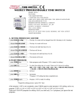
Screen 1: Current Conditions
Screen 1, (Figure 17) shows a brief summary of the current conditions of the house.
There are no editable values in this screen; it is for viewing only.
1. Operating Mode - this indicates the mode of the current Control. The three
possible modes are Power, Natural, and Tunnel.
2. Control Temperature - this is the reading of the current Mode Sensor (or
Sensors). The Sensor or Sensor(s) that make up the Mode Sensor is indicated by
an (*) in the list of Sensors. The current mode sensor determines when the
Control changes to a different mode.
3. Set Temperature - this is the temperature you want to achieve in your house
through the use of heating, cooling, and ventilation.
4. Sensors - each Sensor that is being used in the house will show a current
temperature. If a Sensor is not used, the area will be blank. If a Sensor is out of
range, it will be indicated by “#” in place of a temperature.
5. (*) - this indicates that this Sensor is a Mode Sensor for the current mode. If more
than one (*) appears, the Mode Sensor(s) temperature will be the average of
those Sensors.
6. Static Pressure - indicates the current static pressure in the house. If static
pressure is not being used this area will be blank. If there is a reading that is out
of range, it will be indicated by “#” in place of a static pressure reading.
7. Check Switches - this will appear (flashing) if any of the manual switches are in
a position other than “auto”, except for any switches that are not used. It can be
DANGEROUS to operate with switches in the "Off" Position.
8. Time and Date - shows the current time and date.
9. House RH - indicates the current relative humidity in the house. If relative
humidity is not being used this area will be blank.
10. Check Alarms - this will appear (flashing) if the Control detects an alarm
condition. This will continue to appear until the condition is corrected.
11. Outside Sensor - This is where the outside Sensor reading is displayed if the
outside Sensor choice is set up in screen 13.
12. Egg Room Temp- Current egg room temperature.
13. Egg Room Humidity- Current egg room humidity.
Overview of Screens
1
2
3
5
4
6
8
12
Figure 17. Screen 1: Current Conditions
13
11
9

Overview of Screens Chore-Tronics® 2 Control (Breeder Edition)
20
MT1912A
Screen 2: Auxiliary Data
To view the Auxiliary Data Screen, push the "Auxiliary Data" subject button.
(Button 2)
(Auxiliary Data Screen) General Tab
To access the Auxiliary Data "General" screen, press one of the Tab Keys under
"General".
Figure 18. Auxiliary Data: General Tab
1. Cool Pad Output Status-This indicates the Cool Pad
function's current amount of water on time. If the value
of the number is 0 then the Cool Pad function is cur-
rently not operating. If the word BLOCKED appears
then the Cool Pad function is currently being blocked
from operation by the relative humidity sensor.
2. Air Speed-The current air speed in the house is dis-
played here. If the air speed is less than 125 feet/min
(.63 m/s) then the word LOW will be displayed as the
airspeed.
3. Light Dimmer Output percentage-The current actual
light dimmer level percentage is shown here. Values can
range from 0-100%.
4. Spare Temperature Sensor-The current reading of the
spare temperature sensor is displayed here. The spare
temperature sensor can be assigned to a spare output
and can have its own maximum and minimum alarm
setting separate from the controlling temperature sen-
sors.
5. Today's Water usage-The current water usage for today
since midnight for each drinker Water Meter connected
to the control is displayed here.
6. Today's Feed usage-The current feed usage for today
since midnight for each feed scale connected to the con-
trol is displayed here.
7. Today's Auxiliary digital input usage-The current read-
ing of each auxiliary digital input (non-drinker Water
Meters, electric meters, gas meters, etc.) is displayed
here. Each auxiliary Input can be given a unique name
using the alphanumeric key in the Setup-General
Screen.
8. Bird Age-Current age of the birds in days. The number
in parentheses indicates the age of the bird in weeks and
days. For example: if the birds are 38 days old the num-
ber in the parentheses will show 5.3 (5 weeks and 3
days).
2
3
4
5
6
7
1
8
Or
/