Page is loading ...

1
Chapter 1 Introduction www.d.com
DT122-HD
Desktop Box PC
User’s Manual
A-363-M-2008

2
Chapter 1 Introduction www.dfi .com
Copyright
This publication contains information that is protected by copyright. No part of it may be re-
produced in any form or by any means or used to make any transformation/adaptation without
the prior written permission from the copyright holders.
This publication is provided for informational purposes only. The manufacturer makes no
representations or warranties with respect to the contents or use of this manual and specifi-
cally disclaims any express or implied warranties of merchantability or fitness for any particu-
lar purpose. The user will assume the entire risk of the use or the results of the use of this
document. Further, the manufacturer reserves the right to revise this publication and make
changes to its contents at any time, without obligation to notify any person or entity of such
revisions or changes.
Changes after the publication’s first release will be based on the product’s revision. The web-
site will always provide the most updated information.
© 2015. All Rights Reserved.
Trademarks
Product names or trademarks appearing in this manual are for identification purpose only and
are the properties of the respective owners.
FCC and DOC Statement on Class A
This equipment has been tested and found to comply with the limits for a Class A digital
device, pursuant to Part 15 of the FCC rules. These limits are designed to provide reason-
able protection against harmful interference when the equipment is operated in a residential
installation. This equipment generates, uses and can radiate radio frequency energy and, if not
installed and used in accordance with the instruction manual, may cause harmful interference
to radio communications. However, there is no guarantee that interference will not occur in a
particular installation. If this equipment does cause harmful interference to radio or television
reception, which can be determined by turning the equipment off and on, the user is encour-
aged to try to correct the interference by one or more of the following measures:
• Reorient or relocate the receiving antenna.
• Increase the separation between the equipment and the receiver.
• Connect the equipment into an outlet on a circuit different from that to which the receiver
is connected.
• Consult the dealer or an experienced radio TV technician for help.
Notice:
1. The changes or modifications not expressly approved by the party responsible for compli-
ance could void the user’s authority to operate the equipment.
2. Shielded interface cables must be used in order to comply with the emission limits.

3
Chapter 1 Introduction www.dfi .com
Table of Contents
Copyright .............................................................................................................2
Trademarks ........................................................................................................2
FCC and DOC Statement on Class B .....................................................2
About this Manual ..........................................................................................4
Warranty ..............................................................................................................4
Static Electricity Precautions ......................................................................4
Safety Measures ..............................................................................................4
About the Package .........................................................................................5
Chapter 1 - Introduction .............................................................................6
Overview ....................................................................................................... 6
Key Features ................................................................................................ 6
Specifications ............................................................................................... 7
Getting to Know the DT122-HD .............................................................8
Mechanical Dimensions .............................................................................9
Motherboad Dimensions ........................................................................... 9
Chapter 2 - Getting Started .....................................................................10
Preparing the System ..............................................................................10
Installing Devices .....................................................................................10
Configuring the BIOS .............................................................................. 10
Installing the Operating System ..........................................................10
Installing the Drivers ...............................................................................10
Chapter 3 - Installing Devices .............................................................. 11
Installing a 2.5” or 3.5” SATA Drive ................................................... 12
Installing a 2.5” SATA Drive .......................................................................12
Installing a 3.5” SATA Drive .......................................................................14
Installing the PCI or PCIe x16 Expansion Card ...............................15
Chapter 4 - Jumper Settings ................................................................. 17
Clear CMOS Data ......................................................................................17
PS/2 Keyboard/Mouse Power Select ...................................................17
USB Power Select .....................................................................................18
Power-on Select ........................................................................................18
Mini PCIe Signal Select ...........................................................................19
LCD/Inverter Power Select ....................................................................19
Panel Power Select ..................................................................................20
LVDS Channel and bpp Select ...............................................................20
Digital I/O Power Select .........................................................................21
Digital I/O Output State .........................................................................21
Chapter 5 - Ports and Connectors ........................................................22
Rear Panel I/O Ports ................................................................................22
PS/2 Keyboard/Mouse Port .........................................................................22
RJ45 LAN Ports .........................................................................................23
USB Ports .................................................................................................23
Graphics Intefaces .....................................................................................24
COM (Serial) Ports .....................................................................................25
Audio ........................................................................................................25
I/O Connectors ..........................................................................................26
SATA (Serial ATA) Connectors .....................................................................26
Digital I/O Connector ................................................................................ 26
Digital I/O Power Connector ...................................................................... 26
Cooling Fan Connectors .............................................................................27
Power Connectors .....................................................................................27
LVDS LCD Panel Connector .........................................................................28
LCD/Inverter Power Connector ...................................................................28
Chassis Intrusion Connector .......................................................................29
Front Panel Connector ................................................................................29
Standby Power LED ...................................................................................30
S/PDIF Connector ......................................................................................30
Expansion Slots .........................................................................................31
Battery .....................................................................................................31
Chapter 6 - Mounting Options .............................................................. 32
Chapter 7 - BIOS Setup ...........................................................................34
Overview.......................................................................................................34
AMI BIOS Setup Utility .............................................................................35
Main .........................................................................................................35
Advanced ..................................................................................................35
Chipset .....................................................................................................44
Boot .........................................................................................................50
Security ....................................................................................................51
Save & Exit ...............................................................................................51
Updating the BIOS ...................................................................................52
Notice: BIOS SPI ROM ............................................................................52
Chapter 8 - Supported Software .........................................................53
Chapter 9 - Digital I/O Programming Guide ..................................61
Appendix A - Watchdog Sample Code................................................69
Appendix B - System Error Message ...................................................70
Appendix C - Troubleshooting Checklist ............................................71

4
Chapter 1 Introduction www.d.com
About this Manual
An electronic file of this manual can be obtained from the DFI website at www.dfi.com.
To download the user’s manual from our website, please go to “Support” > “Download Center.”
On the Download Center page, select your product or type the model name and click “Search”
to find all technical documents including the user’s manual for a specific product.
Warranty
1. Warranty does not cover damages or failures that arised from misuse of the product,
inability to use the product, unauthorized replacement or alteration of components and
product specifications.
2. The warranty is void if the product has been subjected to physical abuse, improper instal-
lation, modification, accidents or unauthorized repair of the product.
3. Unless otherwise instructed in this user’s manual, the user may not, under any circum-
stances, attempt to perform service, adjustments or repairs on the product, whether in or
out of warranty. It must be returned to the purchase point, factory or authorized service
agency for all such work.
4. We will not be liable for any indirect, special, incidental or consequencial damages to the
product that has been modified or altered.
Static Electricity Precautions
It is quite easy to inadvertently damage your PC, system board, components or devices even
before installing them in your system unit. Static electrical discharge can damage computer
components without causing any signs of physical damage. You must take extra care in han-
dling them to ensure against electrostatic build-up.
1. To prevent electrostatic build-up, leave the system board in its anti-static bag until you are
ready to install it.
2. Wear an antistatic wrist strap.
3. Do all preparation work on a static-free surface.
4. Hold the device only by its edges. Be careful not to touch any of the components, contacts
or connections.
5. Avoid touching the pins or contacts on all modules and connectors. Hold modules or con
nectors by their ends.
Safety Measures
To avoid damage to the system:
• Use the correct AC input voltage range.
To reduce the risk of electric shock:
• Unplug the power cord before removing the system chassis cover for installation or servic-
ing. After installation or servicing, cover the system chassis before plugging the power cord.
Battery:
• Danger of explosion if battery incorrectly replaced.
• Replace only with the same or equivalent type recommend by the manufacturer.
• Dispose of used batteries according to local ordinance.
Important:
Electrostatic discharge (ESD) can damage your processor, disk drive and other com-
ponents. Perform the upgrade instruction procedures described at an ESD worksta-
tion only. If such a station is not available, you can provide some ESD protection by
wearing an antistatic wrist strap and attaching it to a metal part of the system chas-
sis. If a wrist strap is unavailable, establish and maintain contact with the system
chassis throughout any procedures requiring ESD protection.

5
Chapter 1 Introduction www.d.com
About the Package
The package contains the following items. If any of these items are missing or damaged,
please contact your dealer or sales representative for assistance.
• 1 DT122-HD system unit
• 1 CPU cooler
• 1 HDD drive bay kit
• 1 Quick Installation Guide
Optional Items
• Power Cord
The board and accessories in the package may not come similar to the information listed
above. This may differ in accordance to the sales region or models in which it was sold. For
more information about the standard package in your region, please contact your dealer or
sales representative.
Before Using the System
Before powering-on the system, prepare the basic system components.
If you are installing the system board in a new system, you will need at least the following
internal components.
• Memory module
• Storage devices such as hard disk drive, CD-ROM, etc.
You will also need external system peripherals you intend to use which will normally include at
least a keyboard, a mouse and a video display monitor.
Safety Precautions
• Use the correct DC input voltage range.
• Unplug the power cord before removing the system chassis cover for installation or servic-
ing. After installation or servicing, cover the system chassis before plugging the power cord.
• Danger of explosion if battery incorrectly replaced.
• Replace only with the same or equivalent type recommend by the manufacturer.
• Dispose of used batteries according to local ordinance.
• Keep this system away from humidity.
• Place the system on a stable surface. Dropping it or letting it fall may cause damage.
• The openings on the system are for air ventilation to protect the system from overheating.
DO NOT COVER THE OPENINGS.
• Place the power cord in such a way that it will not be stepped on. Do not place anything on
top of the power cord. Use a power cord that has been approved for use with the system
and that it matches the voltage and current marked on the system’s electrical range label.
• If the system will not be used for a long time, disconnect it from the power source to avoid
damage by transient overvoltage.
• If one of the following occurs, consult a service personnel:
- The power cord or plug is damaged.
- Liquid has penetrated the system.
- The system has been exposed to moisture.
- The system is not working properly.
- The system dropped or is damaged.
- The system has obvious signs of breakage.
• The unit uses a three-wire ground cable which is equipped with a third pin to ground the
unit and prevent electric shock. Do not defeat the purpose of this pin. If your outlet does
not support this kind of plug, contact your electrician to replace the outlet.
• Disconnect the system from the DC outlet before cleaning. Use a damp cloth. Do not use
liquid or spray detergents for cleaning.

6
Chapter 1 Introduction www.dfi .com
Chapter 1 - Introduction
Chapter 1
Overview
Key Features
Model Name DT122-HD
Processor
4th Generation Intel
®
Core
TM
processors
Chipset
Intel
®
H81 Express chipset
LAN
2 LAN ports
COM
2 COM ports
Displays
1 HDMI, 1 DVI-I
USB
4 USB 2.0 ports
2 USB 3.0 ports
Audio
Mic-in, Line-in, Line-out
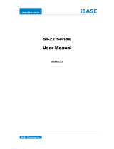
Front View
Rear View

7
Chapter 1 Introduction www.dfi .com
I/O Ports
• Front Panel
- 1 Power button
- 1 Reset button
- 2 LED indicators: Power, HDD
• Rear Panel
- 1 mini-DIN-6 for PS/2 mouse/keyboard
- 2 USB 3.0
- 4 USB 2.0
- 2 DB-9 RS232 COM
- 1 HDMI
- 1 DVI-I
- 2 RJ45 LAN
- Mic-in, line-in and line-out jacks
Environment
• Temperature
- Operating: 0
o
C~45
o
C
- Storage: -20
o
C~60
o
C
• Humidity
- 85% RH at 45
o
C, 1 week
• Operating Vibration
- IEC68-2-64
• Operating Shock
- Operating: 3G peak acceleration (11 msec. duration)
- Non-operating: 5G peak acceleration (11 msec. duration)
Construction
• Front panel: aluminum
• Rear chassis: sheet metal
Mounting
• 2 types of wall mount bracket
- Type A - Type B
• Brackets and screws (optional)
Dimensions
• 300mm x 75mm x 217mm (W x H x D)
Weight
• 3.7 kg
OS Support
• Windows 7, WES 7, Windows 8, WES 8
• Linux (Distribution available upon request)
Certifi cation
• CE
• FCC Class A
• RoHS
• UL
Other Features
• Watchdog Timer function
Specifications
Processor System
• Processors:
- 4th Generation Intel
®
Core
TM
processors (22nm process technology)
: Intel
®
Core
TM
i7-4790S (8M Cache, up to 4.0 GHz); 65W
: Intel
®
Core
TM
i7-4770S (8M Cache, up to 3.9 GHz); 65W
: Intel
®
Core
TM
i7-4770TE (8M Cache, up to 3.3 GHz); 45W
: Intel
®
Core
TM
i5-4590S (6M Cache, up to 3.7 GHz); 65W
: Intel
®
Core
TM
i5-4590T (6M Cache, up to 3.0 GHz); 35W
: Intel
®
Core
TM
i5-4570S (6M Cache, up to 3.6 GHz); 65W
: Intel
®
Core
TM
i5-4570TE (4M Cache, up to 3.3 GHz); 35W
: Intel
®
Core
TM
i3-4360 (4M Cache, 3.7 GHz); 54W
: Intel
®
Core
TM
i3-4350T (4M Cache, 3.1 GHz); 35W
: Intel
®
Core
TM
i3-4340TE (4M Cache, 2.6 GHz); 35W
: Intel
®
Core
TM
i3-4330 (4M Cache, 3.5 GHz); 54W
: Intel
®
Core
TM
i3-4330TE (4M Cache, 2.4 GHz); 35W
: Intel
®
Pentium
®
G3420 (3M Cache, 3.2 GHz); 53W
: Intel
®
Pentium
®
G3320TE (3M Cache, 2.3 GHz); 35W
: Intel
®
Celeron
®
G1820 (2M Cache, 2.7 GHz); 53W
: Intel
®
Celeron
®
G1820TE (2M Cache, 2.2 GHz); 35W
• Intel
®
H81 Express chipset
Memory
• Two 204-pin DDR3 SODIMM sockets
• Supports DDR3 1333/1600MHz
• Supports up to 16GB system memory
• Supports dual channel memory interface
Graphics
• Intel
®
HD Graphics
• Display ports: 1 HDMI, 1 DVI-I
• HDMI: resolution up to 4096x2304 @ 24Hz or 2560x1600 @ 60Hz
• DVI-I, VGA: resolution up to 1920x1200 @ 60Hz
Storage
• Up to 2x 2.5" or 1x 3.5" SATA drive bay
- SATA 3.0 port with data transfer rate up to 6Gb/s
Ethernet
• Intel
®
I210 PCI Express Gigabit Ethernet controller
• Intel
®
I217 Gigabit Ethernet Phy
• Integrated 10/100/1000 transceiver
• Fully compliant with IEEE 802.3, IEEE 802.3u, IEEE 802.3ab
Expansion Slots
• 1 expansion slot
- 1 PCIe x16 or PCI slot
• 1 Mini PCIe slot
- Supports USB and PCIe signals
- Supports mSATA
- Supports half size or full size Mini PCIe card
Audio
• Realtek ALC886 5.1-channel High Defi nition Audio
Power
• Power type
- Flex ATX
• Power input voltage
- AC 100-240V, 250W
Cooling System
• 1 CPU cooler
Chapter 1

8
Chapter 1 Introduction www.dfi .com
Getting to Know the DT122-HD
Chapter 1
Front View
Power Button
Press to power-on or power-off the system.
Reset Button
Press to reset the system.
HDD LED
Indicates the status of the hard drive.
Power LED
Indicates the power status of the system.
Rear View
DVI-I Port
Used to connect a DVI device.
HDMI
Used to connect an HDMI device.
COM Ports
Used to connect serial devices.
USB Ports
Used to connect USB 3.0/2.0/1.1 devices.
LAN Ports
Used to connect the system to a local area network.
Line-out
Used to connect to a speaker.
Line-in
Used to connect any audio devices such as Hi-fi set, CD player, tape player, AM/FM radio tuner,
synthesizer, etc
.
Mic-in
Used to connect an external microphone.
PS/2 KB/Mouse
Used to connect a PS/2 keyboard and PS/2 mouse.
Line-out
Mic-in
Line-in
HDMI
COM 1
USB 2.0
Power LED
Reset Button
Power Button
HDD LED
COM 2
DVI-I
PS/2 KB/MS
USB 2.0
USB 3.0
LAN 2
LAN 1

9
Chapter 1 Introduction www.dfi .com
Mechanical Dimensions
Chapter 1
Motherboard Dimensions
Front View
Right View
Left View
Rear View
300.00
74.00
78.00
217.20
0.00
0.00
46.97
124.47
49.47
154.94
140.94
153.29
10.16
159.84
18.23
45.88
83.42
111.09
132.42
151.76
157.48
22.86
39.32
64.32
83.89
107.88
154.94
0.00
15.92
17.13
92.14
100.63
137.63
111.51
157.48
1.56

10
Chapter 2 Getting Started www.d.com
Chapter 2 - Getting Started
Chapter 2
Preparing the System
Before you start using the system, you need the following items:
• SATA hard drive
• AC power adapter
• PS/2 or USB keyboard
• PS/2 or USB mouse
• CD-ROM drive (for installing software/drivers)
• Screwdriver
• Memory module (optional)
Installing Devices
The following are devices that can be installed in the system.
• Memory module
• SATA hard drive
Configuring the BIOS
To get you started, you may need to change configurations such as the date, time and the
type of hard disk drive.
1. Power-on the system.
2. After the memory test, the message “Press DEL to run setup” will appear on the screen.
Press the Delete key to enter the AMI BIOS setup utility.
Installing the Operating System
Most operating system software can be installed using a DVD (and DVD burner) or bootable
USB drive.
Please refer to your operating system manual for instructions on installing an operating system.
Installing the Drivers
The system requires you to install drivers for some devices to operate properly. Refer to the
Supported Software chapter for instructions on installing the drivers.

www.dfi .com
11
Chapter 3 Installing Devices
Chapter 3
Chapter 3 - Installing Devices
1. Make sure the system and all other peripheral devices connected to it has been powered-off.
2. Disconnect all power cords and cables.
3. The 4 mounting screws on the sides of the system are used to secure the cover to the chassis.
Remove these screws and then put them in a safe place for later use.
Mounting
screw
Mounting
screw
4. After removing the mounting screws, slide the cover backwards.
Slide the Cover Backward
5. The DIMM sockets and SATA drive bay are readily accessible after removing the chassis cover.
DIMM socket
2.5"/3.5" SATA
drive bay

www.dfi .com
12
Chapter 3 Installing Devices
Chapter 3
Installing a 2.5" or 3.5" SATA Drive
Installing a 2.5” SATA Drive
2. Turn to the other side of the drive bay and remove the 4 mounting screws that secure the HDD
brackets to the drive bay.
Mounting screw
Mounting screw
Mounting screw
Drive bay
Drive bay
3. Align the mounting holes of the SATA drive with the mounting holes on the HDD bracket and
then use the provided mounting screws to secure the drive in place.
Mounting screw
SATA drive
HDD bracket
Mounting screw
1. Remove the 4 mounting screws that secure the drive bay to the chassis and then remove the
drive bay.

www.dfi .com
13
Chapter 3 Installing Devices
Chapter 3
4. Turn to the other side of the drive bay. Use the provided mounting screws from step 2 to
secure the SATA drive (with HDD bracket) onto the drive bay.
Mounting screw
Drive bay
Mounting screw
5. Place the SATA drive bay assembly into the chassis. Secure the SATA drive bay with the
mounting screws you removed in step 1.
Mounting screw
Mounting screw
6. Connect the SATA data cable and SATA power cable to the connectors on the SATA drive.
SATA data cable
SATA power
cable

www.dfi .com
14
Chapter 3 Installing Devices
Chapter 3
lnstalling a 3.5" SATA Drive
Drive bay
spacer
spacer
3. Place the SATA drive on the drive bay. Align the mounting holes of the SATA drive with the
mounting holes on the drive bay.
SATA drive
Drive bay
4. Use the provided mounting screws to secure the SATA drive onto the drive bay.
5. Place the drive bay into the chassis. Secure the drive bay with the mounting screws you
removed in step 1.
Mounting screw
Drive bay
Mounting screw
Mounting screw
Mounting screw
6. Connect the SATA data cable and SATA power cable to the connectors on the SATA drive.
SATA data cable
SATA power cable
1. Remove the 4 mounting screws that secure the drive bay to the system.
Mounting screw
Mounting screw
Drive bay
2. Insert the spacer into the anti-shock bumper. You will fi nd the spacers in the HDD drive bay kit
that comes with the DT122 package.

www.dfi .com
15
Chapter 3 Installing Devices
Chapter 3
Installing the PCI or PCIe x16 Expansion Card
Important:
When inserting the riser card,
please select a card within
175mm (as shown on the next
picture).
Mounting bracket
Mounting screw
Bracket
PCIe x16 slot
Mounting bracket and
mounting screw
PCI slot
1.
The PCIe x16 on the motherboard is used to insert a TS200-1P or TS200-1E riser card.
To install the expansion card, you need to remove the mounting bracket and the mounting
screw that secure the bracket to the chassis and then remove the bracket
. Put the screw and
the brackets in a safe place for later use.
T200-1P
T200-1E

www.dfi .com
16
Chapter 3 Installing Devices
Chapter 3
2. Insert the Expansion card with a bracket into the PCI or PCIe x16 slot that is on the riser card.
Replace the screw you removed in step 1 to secure the bracket in place.
Mounting bracket
and mounting
screw
PCI
Bracket
Expansion card
Rear view
Note:
The Expansion card used in the above illustrations may not resemble the actual cards.
These illustrations are for reference only.

17
Chapter 4 Jumper Settings
Chapter 4
www.dfi .com
Chapter 4 - Jumper Settings
Clear CMOS Data
JP1 is used to select the power of the PS/2 keyboard/mouse port. Selecting +5V_standby will
allow you to use the PS/2 keyboard or PS/2 mouse to wake up the system.
PS/2 Keyboard/Mouse Power Select
JP1
Important:
The +5VSB power source of your power supply must support ≥720mA.
2-3 On:
+5V_standby
1-2 On: +5V
(default)
3
1
2
3
1
2
If you encounter the followings,
a) CMOS data becomes corrupted.
b) You forgot the supervisor or user password.
you can reconfigure the system with the default values stored in the ROM BIOS.
To load the default values stored in the ROM BIOS, please follow the steps below.
1. Power-off the system and unplug the power cord.
2. Set JP9 pins 2 and 3 to On. Wait for a few seconds and set JP9 back to its default setting,
pins 1 and 2 On.
3. Now plug the power cord and power-on the system.
JP9
2-3 On:
Clear CMOS Data
1-2 On: Normal (default)
312
312

18
Chapter 4 Jumper Settings
Chapter 4
www.dfi .com
These jumpers are used to select the power of the USB ports. Selecting +5V_standby will
allow you to use a USB device to wake up the system.
USB Power Select
USB 0-1 (JP5)
USB 2-3 (JP8)
Important:
If you are using the Wake-On-USB Keyboard/Mouse function for 2 USB ports, the
+5V_standby power source of your power supply must support ≥1.5A. For 3 or more
USB ports, the +5V_standby power source of your power supply must support ≥2A.
Power-on Select
1-2 On:
Power-on via power button
(default)
2-3 On:
Power-on via AC power
USB 4-5
(JP6)
2-3 On:
+5V_standby
1-2 On: +5V
(default)
JP10 is used to select the method of powering on the system. If you want the system to
power-on whenever AC power comes in, set JP10 pins 2 and 3 to On. If you want to use the
power button, set pins 1 and 2 to On.
When using JP10 “Power On” feature to power the system back on after a power failure oc-
curs, the system may not power on if the power lost is resumed within 5 seconds (power
flicker).
312
312
1
3
2
1
3
2
2-3 On:
+5V_standby
1-2 On: +5V
(default)
USB 10-11
(JP13)
2-3 On:
+5V_standby
1-2 On: +5V
(default)
3
1
2
3
1
2
JP10
1
3
2
1
3
2

19
Chapter 4 Jumper Settings
Chapter 4
www.dfi .com
Mini PCIe Signal Select
JP12
2-5-8-11, 3-6-9-12 On:
mSATA
1-4-7-10, 2-5-8-11 On:
PCIe (default)
12
10
3
1
JP12 is used to select the Mini PCIe signal.
12
10
3
1
LCD/Inverter Power Select
1-2 On: +12V
2-3 On:
+5V (default)
312
312
JP2
JP2 is used to select the power level of LVDS LCD inverter connector.

20
Chapter 4 Jumper Settings
Chapter 4
www.dfi .com
Panel Power Select
JP11
1-2 On: +12V
3-4 On:+5V
5-6 On: +3.3V
(default)
1
6
4
2
5
3
JP11 is used to select the power supplied with the LCD panel.
Important:
Before powering-on the system, make sure that the power settings of JP11 match
the LCD panel’s specification. Selecting the incorrect voltage will seriously damage the
LCD panel.
LVDS Channel and bpp Select
SW1
OFF
OFF
1 On: Single LVDS
1 Off: Dual LVDS
2 On: VESA (24bpp)
2 Off: JEIDA or VESA
(18bpp)
Switch 1 is designed to select the LVDS channel and the color of bits per pixel on the system.
1
6
4
2
5
3
1
6
4
2
5
3
/