Page is loading ...

Commercial Gas
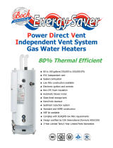
Ultra High Efficiency Water Heater
T
he Ultra High Efficiency Water Heater Models Feature:
■ Thermal Efficiency Up To 99.1%.
■ 6
0 Gallon Tank Capacity in 125,000, 150,000 and 199,999
BTU/hr Inputs
.
■ 100 Gallon Tank Capacity in 150,000, 199,999, 250,000, 300,000
and 399,999 BTU/hr Inputs
.
■ Flexible V
enting—
Conventional, Thr
ough-the-Wall or Direct Vent.
■ Three Pass Flue System.
■ Low NOx Premix Power Burner.
■ Ultra Quiet Operation.
■ Submerged Combustion Chamber.
■ 1" NPT Side Connection For Hydronic Applications.
■ Electronic Controls.
■ Zero Inch Clearance To Combustibles.
■ Vitraglas
®
Lined Tank.
■ Four Protective Magnesium Anode Rods (except EF-100T-399).
■ Powered Anode Rods (only EF-100T-399).
■ Hand Hole Cleanout—Allows inspection of tank interior.
■ Factory Installed Hydrojet
®
Sediment Reduction System.
■ Factory Installed Dielectric Fittings.
■ Non-CFC Foam Insulation.
■ 3" Optional Concentric Vent Kit.
■ ASME Construction Available.
■ NSF Construction A
vailable With Optional Kit
.
■ Brass Drain Valve.
■ T&P Relief Valve Factory Installed.
■ Three Year Limited Warranty On Steel Tank.
■ One Year Limited Warranty On Parts.
MANUF
ACTURED UNDER ONE OR MORE OF THE FOLLOWING U.S. P
A
TENTS:
7,063,133 B2; 5,954,492; 5,954,492; 5,761,379; 5,943,984; 5,081,696; 5,988,117; 6,142,216; 5,199,385; 5,574,822; 5,372,185;
5,485,879; 5,277,171; (B1)5,341,770; 5,660,165; 5,596,952; 5,682,666; 4,904,428; 5,023,031; 5,000,893; 4,669,448; 4,829,983; 4,808,356; 5,115,767; 5,092,519; 5,052,346; 4,416,222; 4,628,184; 4,861,968;
4,672,919; Re. 34,534. OTHER U.S. AND FOREIGN PATENT APPLICATIONS PENDING. CURRENT CANADIAN PATENTS: 1,272,914; 1,280,043; 1,289,832; 2,045,862; 2,112,515; 2,108,186; 2,107,012; 2,092,105.
V
itraglas
®
and Hydr
ojet
®
ar
e registered trademarks of Bradford White
®
Corporation.
©2006, Bradford White Corporation. All rights reserved. Printed in U.S.A.
3 or 5-Year Limited Tank Warranties / 1-Year Limited Warranty on Component Parts.
For more information on warranty, please visit www.bradfordwhite.com
For pr
oducts installed in USA, Canada and Puer
to Rico. Some states do not allow limitations on warranties.
See complete copy of the warranty included with the heater.
800-B-1006-A
Photo is of
EF-100T-199

eF Series
®
Standard Equipment Features:
Thermal Efficiency up to 99.1%—Fully condensing design.
Three Pass Flue System—The three pass flue system
keeps the hot combustion gases moving at a high velocity.
The combination of high turbulence and velocity causes an
enormous rate of heat transfer into the water.
Low NOx Premix Power Burner—Developed for the
eFSeries
®
, a turbulent flame shoots down the submerged
combustion chamber. This turbulence causes a thorough
mixing of the gas and air for optimum combustion and high
heat transfer efficiencies. — Far exceeds California
e
mission requirements.
Submerged Combustion Chamber—Submerging the
combustion chamber in the center of the water storage
tank minimizes radiant heat loss and improves efficiency.
Non-CFC Foam Insulation—Surrounds the tank surface,
saving energy by retarding loss of heat.
Electronic Controls—Adjustable electronic thermostat for
control between 80°F and 180°F. The recycling Energy Cut
Off (ECO) shuts off all gas flow in an event of an overheat
condition.
Zero Inch Clearance—The eFSeries
®
jacket is cool to the
touch and is approved for zero inch clearance to
combustibles for unsurpassed installation flexibility.
Vitraglas
®
Lined Tank—Bradford White’s water heater
tanks are protected from the corrosive effects of hot water
by an exclusive ceramic porcelain-like coating. Our high
silica Vitraglas
®
lining provides a tough interior surface for
Bradford White’s water heater tanks.
Protective Magnesium Anode Rods—Employed to
provide an extra measure of corrosion protection for longer
life. Each eF heater has 4 anodes, except the EF-100T-399
which has 2 powered anode rods and one non-powered
anode rod.
Factory Installed Hydrojet
®
Sediment Reduction
System—
Cold inlet sediment reduction device made of
stainless steel for increased durability. Helps prevent
sediment build up in tank.
Factory Installed Dielectric Fittings—All heaters equipped
with special water heater nipples for longer heater life. No
special dielectric fittings to buy
.
Flexible Venting—The eF Series
®
can vent vertically or
horizontally with either 3" or 4" PVC, CPVC or ABS vent
p
ipe, and is approved for direct vent closed combustion
applications, or those applications that require inside air for
c
ombustion. Foam Core pipe is permitted on the entire
venting system. The eF Series
®
is also approved for
unbalanced venting, which means the air intake pipe
doesn't have to be vented the same distance as the
exhaust.
(NOTE: Air intake cannot exceed exhaust by more than
30 feet.)
Determining required vent length
1. Determine the total length of straight vent pipe (in feet)
required for both the intake and the exhaust.
2. Add 5 feet of venting for every 90˚ elbow.
3. Add 2 1⁄2 feet of venting for every 45˚ elbow.
4. Total vent length cannot exceed "Max Length" in the
above venting table.
5. Air intake cannot exceed exhaust by more than 30 feet
in any venting situation.
NOTICE: Do not include the 3" exhaust elbow or vent
terminals in determining maximum vent length.
Three year limited warranty on steel tank —
Heavy
gauge steel automatically formed, rolled and welded to
assure a continuous seam for glass lining.
One year limited warranty on parts
Ultra High Efficiency Water Heaters
Intake/
Combustion
Air
Rain Cap
Vent
Exhaust
46
3
/4"
eF Series
®
Optional Equipment Features:
Maxitrol Gas Pressure Regulating valve—Ensures
proper supply pressure to eF unit of 7" to 11" W.C.
(pr
ovided incoming pr
essure is between 1/2 and 2 psi).
This can be ordered as a separate part, or as part of
the heater. For the separate part, please use
p/n 243-45517-00 (not available for use with the
EF-100T
-399).
Concentric Vent Terminal Kit—3" termination fitting
pr
ovides for only one exit opening thr
ough wall or r
oof
(p/n 239-44069-01).
NSF Compliance Kit—p/n 265-44542-04.
Model
Number
EF-60T-125
EF-60T-150
EF-60T-199
EF-100T-150
EF-100T-199
EF-100T-250
EF-100T-300
EF-100T-399
Max. 3" PVC,
ABS & CPVC
120 ft.
100 ft.
80 ft.
120 ft.
100 ft.
80 ft.
60 ft.
50 ft.
Max. 4" PVC,
ABS & CPVC
170 ft.
150 ft.
130 ft.
170 ft.
150 ft.
130 ft.
110 ft.
100 ft.
p/n 239-44069-01

Ultra High Efficiency Water Heaters
NOTE: Diagrams are for both the 60 and 100 gallon models.
3
⁄4" NPT Gas Inlet
1
1
⁄2" NPT
Outlet
1
" NPT Space
H
eating Outlet
1" NPT Space
Heating Return
1
1
⁄2" NPT Inlet
3" PVC Exhaust
3" PVC Air Inlet
G
E
B
D
3" PVC
EXHAUST
1
⁄2" NPT CONDENSATE
CONNECTION
2
3
⁄8"
F
A
C
H
T & P Valve
Cleanout
Drain
8
1
⁄4
B
2
8
1
⁄4
Gas Inlet
T & P Valve
8
1
⁄4
E
xhaust
Air Intake
NATURAL GAS AND LIQUID PROPANE GAS
eF Series
®
Commercial Ultra High Efficiency Water Heater
Meet or exceed ASHRAE 90.1b (current standard) C.E.C. Listed
Includes Installed T&P Valve and Electronic Ignition
Model
Number
F
Floor to
Vent
Outlet
in.
Approx.
Shipping
Weight
lbs.
E
Floor to
Gas
Conn.
in.
A
Floor to
Top of
Heater
in.
Input
BTU
1
ST
Hour
Delivery
at 100°F
Rise
Gal.
Stg.
Capacity
U.S.
Gal.
Therm.
Eff.
%
D
Cold
In
in.
C
HW
Out
in.
B
Jacket
Dia.
in.
140°F100°F40°F
Recovery GPH
at Degree Rise
EF-60T-125E-3N(A)
EF-60T-150E-3N(A)
EF-60T-199E-3N(A)
EF-100T-150E-3N(A)
EF-100T-199E-3N(A)
EF-100T-250E-3N(A)
EF-100T-300E-3N(A)
EF-100T-399E-3N(A)
125,000
150,000
199,999
150,000
199,999
250,000
300,000
399,999
★
★
★
★
★
★
★
★
●
●
●
●
●
●
●
●
187
211
265
250
309
364
405
521
V
V
V
V
V
V
V
V
364
423
558
450
597
735
836
1127
145
169
223
180
239
294
335
451
104
121
159
129
171
210
239
322
60
60
60
100
100
100
100
100
96.0
93.0
92.0
99.1
98.5
97.0
92.0
93.0
57
57
57
77
5
/8
77
5
/8
77
5
/8
77
5
/8
77
5
/8
42
42
42
63
63
63
63
63
570
570
570
900
900
900
900
950
28
1
/4
28
1
/4
28
1
/4
28
1
/4
28
1
/4
28
1
/4
28
1
/4
28
1
/4
5
5
5
5
5
5
5
5
1
1
/2
1
1
/2
1
1
/2
1
1
/2
1
1
/2
1
1
/2
1
1
/2
1
1
/2
3
/4
3
/4
3
/4
3
/4
3
/4
3
/4
3
/4
1
3
/4
3
/4
3
/4
3
/4
3
/4
1
1
1
13
13
13
13
13
13
13
13
53
1
/2
53
1
/2
53
1
/2
74
3
/4
74
3
/4
74
3
/4
74
3
/4
73
1
/4
52
1
/2
52
1
/2
52
1
/2
73
1
/8
73
1
/8
73
1
/8
73
1
/8
73
1
/8
40
40
40
60
60
60
60
60
G
Floor to
Air
Intake
in.
H
Floor to
T&P
Conn.
in.
Gas
Conn.
Dia.
in.
Water
Conn.
Dia.
in.
Relief
Valve
Open
in.
Model
Number
F
Floor to
Vent
Outlet
mm.
Approx.
Shipping
Weight
kgs.
E
Floor to
Gas
Conn.
mm.
A
Floor to
Top of
Heater
mm.
Input
kW
1
ST
Hour
Delivery
at 56°C
Rise
Liters
Stg.
Capacity
Liters
Therm.
Eff.
%
D
Cold
In
mm.
C
HW
Out
mm.
B
Jacket
Dia.
mm.
78°C56°C22°C
Recovery LPH
at Degree Rise
EF-60T-125E-3N(A)
EF-60T-150E-3N(A)
EF-60T-199E-3N(A)
EF-100T-150E-3N(A)
EF-100T-199E-3N(A)
EF-100T-250E-3N(A)
EF-100T-300E-3N(A)
EF-100T-399E-3N(A)
36.6
43.9
58.6
43.9
58.6
73.2
87.9
117.2
★
★
★
★
★
★
★
★
●
●
●
●
●
●
●
●
708
799
1003
946
1170
1378
1533
1972
V
V
V
V
V
V
V
V
1378
1601
3112
1703
2260
2782
3165
4266
545
640
844
681
905
1113
1268
1707
394
458
602
488
647
795
905
1219
227
227
227
379
379
379
379
379
96.0
93.0
92.0
99.1
98.5
97.0
92.0
93.0
1448
1448
1448
1972
1972
1972
1972
1972
1067
1067
1067
1600
1600
1600
1600
1600
259
259
259
408
408
408
408
431
718
718
718
718
718
718
718
718
128
128
128
128
128
128
128
128
38
38
38
38
38
38
38
38
19
19
19
19
19
19
19
25
19
19
19
19
19
25
25
25
330
330
330
330
330
330
330
330
1359
1359
1359
1899
1899
1899
1899
1861
1324
1324
1324
1857
1857
1857
1857
1857
994
994
994
1527
1527
1527
1527
1524
G
Floor to
Air
Intake
mm.
H
Floor to
T&P
Conn.
mm.
Gas
Conn.
Dia.
mm.
Water
Conn.
Dia.
mm.
Relief
Valve
Open
mm.
For pr
opane gas models change suf
fix “N” to “X” and r
emove “E” fr
om the model number.
Example: EF-100T-150-3X
V - 115V A.C. Required
•
- Electr
onic Ignition
★ - Listed with California Energy Commission
(A) ASME - All models are available with ASME construction. To order ASME
construction add the (A) to the end of the model number. Example: EF-60T-125E-3NA
Note:
The weight is the same for both ASME and Non-ASME models.
NSF Construction Available with optional kit
Complies with SCAQMD low NOx requirements — 10.39 ng/joule
Design certified by CSA International (formerly AGA/CGA)
Amp Draw range = 1.0 to 1.8 amps and 7.0 amps for EF-100T-399
150 PSI Working Pressure (1034 kPa), 300 PSI Test Pressure (2068 kPa)

Printed in U.S.A.
©2006, Bradford White Corporation. All rights reserved.
Ambler, PA
For U.S. and Canada field service, contact your professional installer or local Bradford White sales representative.
Sales 800-523-2931
●
Fax 215-641-1670 / Technical Support 800-334-3393
●
Fax 269-795-1089
●
Warranty 800-531-2111
●
Fax 269-795-1089
Inter
national:
T
elephone
215-641-9400
●
T
elefax
215-641-9750 / Fax on Demand 888-538-7833 / www
.bradfordwhite.com
Sales / T
echnical Support
866-690-0961 / 905-238-0100
●
Fax 905-238-0105 / www
.bradfordwhitecanada.com
800-B-1006-A
Ultra High Efficiency Water Heaters
All models are design certified by CSA International (formerly AGA/CGA) for up to 180°F (82°C) application as an Automatic
Storage Heater, and an Automatic Circulating Tank Heater.
As an Automatic Storage Heater, all models are complete self-contained water heating systems. It needs no separate
storage tank, pump, wiring or elaborate piping network. When equipped with a mixing valve, it will supply 180°F (82°C)
sanitizing and 140°F (60°C) general purpose hot water simultaneously. These models can be used either as a single unit or
as multiples connected in parallel.
Sample Specification
The water heater shall be a Bradford White model EF-_____ with a rated storage capacity of not less than _____ gallons/
liters, a minimum gas input of __________ BTU/hr, a minimum recovery of _____ GPH/LPH at 100°F (56°C) temperature rise,
and a Thermal Efficiency Rating of ____%. It shall be design certified by CSA International (formerly AGA and CGA) for
180°F (82°C) application, either with or without a separate storage tank. The tank shall be lined with Vitraglas
®
vitreous
enamel and shall have a bolted hand hole cleanout. The tank shall have four extruded magnesium anode rods installed in
separate head couplings (up to 300,000 BTU/hr input) or two powered anode rods and one extruded magnesium anode rod
(for 399,999 BTU/hr input). This water heater shall be equipped with stainless steel cold water inlet, Hydrojet
®
Sediment
Reduction System. The heater shall be insulated with Non-CFC foam. This water heater shall be equipped with an electronic
ignition system, an ASME rated T&P relief valve and a premix closed combustion system for direct venting using either 3"
(76mm) or 4" (102mm) PVC, CPVC or ABS vent pipe. (115V AC required). The water heater shall be factory assembled and
tested. The water heater shall be approved for zero inch clearance to combustibles. The control shall be an adjustable
electronic thermostat to any temperature up to 180°F (82°C). A recycling Energy Cut Off (E.C.O.) shuts off all gas in the
event of an overheat condition. The entire installation shall be made in compliance with state and local codes and
ordinances.
Dimensions and specifications subject to change without notice in accordance with our policy of continuous
product improvement.
/